FIAT DUCATO 2009 Owner handbook (in English)
Manufacturer: FIAT, Model Year: 2009, Model line: DUCATO, Model: FIAT DUCATO 2009Pages: 286, PDF Size: 12.53 MB
Page 171 of 286
170
KNOWING
YOUR CAR
SAFETY
STARTING
AND
DRIVING
WARNING
LIGHTS AND
MESSAGES
IN AN
EMERGENCY
MAINTENANCE
AND CARE
TECHNICAL
SPECIFICATIONS
INDEX
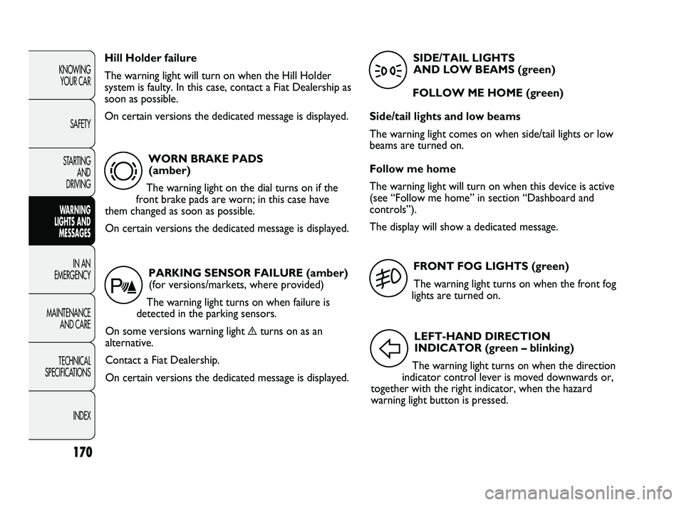
WORN BRAKE PADS
(amber)
The warning light on the dial turns on if the
front brake pads are worn; in this case have
them changed as soon as possible.
On certain versions the dedicated message is displayed.
d
Hill Holder failure
The warning light will turn on when the Hill Holder
system is faulty. In this case, contact a Fiat Dealership as
soon as possible.
On certain versions the dedicated message is displayed.
PARKING SENSOR FAILURE (amber)
(for versions/markets, where provided)
The warning light turns on when failure is
detected in the parking sensors.
On some versions warning light
èturns on as an
alternative.
Contact a Fiat Dealership.
On certain versions the dedicated message is displayed.
t
FRONT FOG LIGHTS (green)
The warning light turns on when the front fog
lights are turned on.
5
LEFT-HAND DIRECTION
INDICATOR (green – blinking)
The warning light turns on when the direction
indicator control lever is moved downwards or,
together with the right indicator, when the hazard
warning light button is pressed.
F
SIDE/TAIL LIGHTS
AND LOW BEAMS (green)
FOLLOW ME HOME (green)
Side/tail lights and low beams
The warning light comes on when side/tail lights or low
beams are turned on.
Follow me home
The warning light will turn on when this device is active
(see “Follow me home” in section “Dashboard and
controls”).
The display will show a dedicated message.
3
161-172 DUCATO LUM EN 7ed 6/21/10 2:14 PM Page 170
Page 172 of 286
171
KNOWING
YOUR CAR
SAFETY
STARTING
AND
DRIVING
WARNING
LIGHTS AND
MESSAGES
IN AN
EMERGENCY
MAINTENANCE
AND CARE
TECHNICAL
SPECIFICATIONS
INDEX
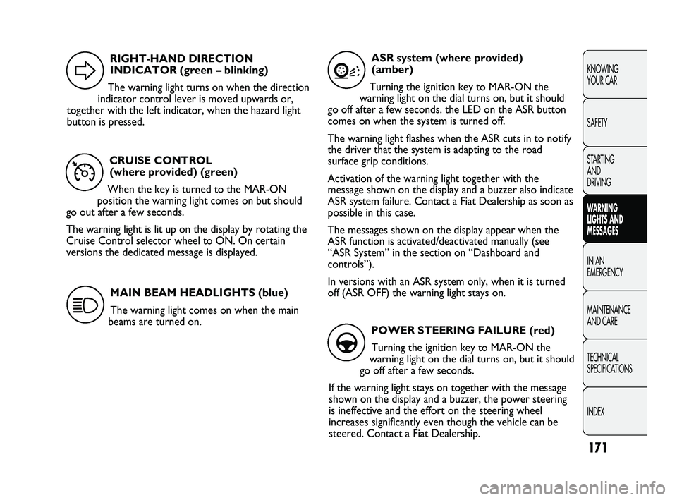
CRUISE CONTROL
(where provided) (green)
When the key is turned to the MAR-ON
position the warning light comes on but should
go out after a few seconds.
The warning light is lit up on the display by rotating the
Cruise Control selector wheel to ON. On certain
versions the dedicated message is displayed.
Ü
RIGHT-HAND DIRECTION
INDICATOR (green – blinking)
The warning light turns on when the direction
indicator control lever is moved upwards or,
together with the left indicator, when the hazard light
button is pressed.
D
MAIN BEAM HEADLIGHTS (blue)
The warning light comes on when the main
beams are turned on.
1
ASR system (where provided)
(amber)
Turning the ignition key to MAR-ON the
warning light on the dial turns on, but it should
go off after a few seconds. the LED on the ASR button
comes on when the system is turned off.
The warning light flashes when the ASR cuts in to notify
the driver that the system is adapting to the road
surface grip conditions.
Activation of the warning light together with the
message shown on the display and a buzzer also indicate
ASR system failure. Contact a Fiat Dealership as soon as
possible in this case.
The messages shown on the display appear when the
ASR function is activated/deactivated manually (see
“ASR System” in the section on “Dashboard and
controls”).
In versions with an ASR system only, when it is turned
off (ASR OFF) the warning light stays on.
V
POWER STEERING FAILURE (red)
Turning the ignition key to MAR-ON the
warning light on the dial turns on, but it should
go off after a few seconds.
If the warning light stays on together with the message
shown on the display and a buzzer, the power steering
is ineffective and the effort on the steering wheel
increases significantly even though the vehicle can be
steered. Contact a Fiat Dealership.
g
161-172 DUCATO LUM EN 7ed 6/21/10 2:14 PM Page 171
Page 173 of 286
The warning light on the dial comes on constantly
(along with the display of the message and a buzzer) to
indicate that the automatic transmission oil
temperature is too high.
POSSIBLE ICE ON ROAD
This indication starts flashing when the outside
temperature reaches or falls below 3 °C to warn the
driver of the possible presence of ice on the road.
The display will show the dedicated message (only for
versions with a multifunction display).
LIMITED RANGE
(versions with multifunction display)
The display will show the dedicated message to warn
the driver that the vehicle’s range is less than 50 km.
SPEED LIMIT EXCEEDED
The display shows the dedicated message when the
vehicle exceeds the set speed limit (see “Multifunction
Display” in section “Dashboard and controls”).
172
KNOWING
YOUR CAR
SAFETY
STARTING
AND
DRIVING
WARNING
LIGHTS AND
MESSAGES
IN AN
EMERGENCY
MAINTENANCE
AND CARE
TECHNICAL
SPECIFICATIONS
INDEX
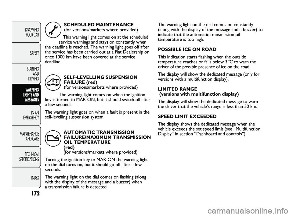
SCHEDULED MAINTENANCE
(for versions/markets where provided)
This warning light comes on at the scheduled
service warnings and stays on constantly when
the deadline is reached. The warning light goes off after
the service has been carried out at a Fiat Dealership or
once 1000 km have been covered at the service
deadline.
õ
AUTOMATIC TRANSMISSION
FAILURE/MAXIMUM TRANSMISSION
OIL TEMPERATURE
(red)
(for versions/markets where provided)
Turning the ignition key to MAR-ON the warning light
on the dial turns on, but it should go off after a few
seconds.
The warning light on the dial comes on flashing (along
with the display of the message and a buzzer) when
a transmission failure is detected.SELF-LEVELLING SUSPENSION
FAILURE (red)
(for versions/markets where provided)
The warning light comes on when the ignition
key is turned to MAR-ON, but it should switch off after
a few seconds.
The warning light goes on when a fault is present in the
self-levelling suspension system.
Œ
t
161-172 DUCATO LUM EN 7ed 6/21/10 2:14 PM Page 172
Page 174 of 286
173
KNOWING
YOUR CAR
SAFETY
STARTING
AND
DRIVING
WARNING
LIGHTS AND
MESSAGES
IN AN
EMERGENCY
MAINTENANCE
AND CARE
TECHNICAL
SPECIFICATIONS
INDEX
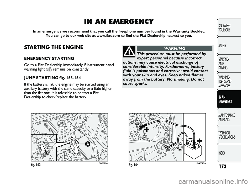
F0N0075mfig. 163F0N0076mfig. 164
STARTING THE ENGINE
EMERGENCY STARTING
Go to a Fiat Dealership immediately if instrument panel
warning light
Yremains on constantly.
JUMP STARTING fig. 163-164
If the battery is flat, the engine may be started using an
auxiliary battery with the same capacity or a little higher
than the flat one. It is advisable to contact a Fiat
Dealership to check/replace the battery.
IN AN EMERGENCY
In an emergency we recommend that you call the freephone number found in the Warranty Booklet.
You can go to our web site at www.fiat.com to find the Fiat Dealership nearest to you.
This procedure must be performed by
expert personnel because incorrect
actions may cause electrical discharge of
considerable intensity. Furthermore, battery
fluid is poisonous and corrosive: avoid contact
with your skin and eyes. Keep naked flames
away from the battery. No smoking. Do not
cause sparks.
WARNING
173-206 DUCATO LUM EN 8ed 27-10-2010 15:45 Pagina 173
Page 175 of 286
174
KNOWING
YOUR CAR
SAFETY
STARTING
AND
DRIVING
WARNING
LIGHTS AND
MESSAGES
IN AN
EMERGENCY
MAINTENANCE
AND CARE
TECHNICAL
SPECIFICATIONS
INDEX
REPLACING A WHEEL
GENERAL INSTRUCTIONS
Wheel changing and correct use of the jack and spare
wheel (for versions/markets where provided) call for
some precautions, which are listed below. Proceed as follows to start the car:
❒raise the flap A to gain access to the positive battery
terminal fig. 163.
❒connect the positive terminals (+ sign near the
terminal) of the two batteries with a jump lead;
❒connect the negative terminal (–) of the auxiliary
battery to the earth point with a second cable as
shown in fig. 164;
❒Start the engine;
❒when the engine has been started, follow the
sequence above in reverse order to remove the
leads.
If after a few attempts the engine does not start, do not
persist but contact the nearest Fiat Dealership.
IMPORTANT Do not directly connect the negative
terminals of the two batteries: any sparks may ignite the
explosive gas which could come out of the battery.
If the auxiliary battery is installed on another vehicle,
prevent any metal parts on the latter and the vehicle
with the flat battery from accidentally coming into
contact.
BUMP STARTING
Never bump start the engine by pushing, towing or
driving downhill. This could cause a flow of fuel into the
catalytic converter and damage it beyond repair.
IMPORTANT Remember that the brake servo and the
power steering system are not activated until the engine
is started, a greater effort will therefore be required to
press the brake pedal or turn the steering wheel.Indicate that the vehicle is stationary
according to the regulations in force:
emergency lights, refracting warning triangle,
etc. Passengers should leave the vehicle,
particularly if it is very loaded, and wait for the
wheel to be changed away from on-coming
traffic. Apply the handbrake.
WARNING
The spare wheel (for versions/markets
where provided) is specific for your
vehicle. Therefore, it must not be used on
vehicles of a different model. Do not use spare
wheels of different models on your vehicle. The
wheel bolts are specific to your vehicle: do not
use them on other models and do not use bolts
of other models.
WARNING
173-206 DUCATO LUM EN 8ed 27-10-2010 15:45 Pagina 174
Page 176 of 286
175
KNOWING
YOUR CAR
SAFETY
STARTING
AND
DRIVING
WARNING
LIGHTS AND
MESSAGES
IN AN
EMERGENCY
MAINTENANCE
AND CARE
TECHNICAL
SPECIFICATIONS
INDEX
Please note that:
❒the jack weight is 4.5 kg;
❒the jack requires no adjustment;
❒the jack cannot be repaired. If it breaks it must be
replaced with a new jack;
❒no tool other than its cranking device may be fitted
on the jack.
Repair and refit the standard wheel as
soon as possible. Do not apply grease to
the bolt threading before assembly: they might
come unscrewed.
WARNING
The jack may only be used to replace
wheels on the car which it equips or
other cars of the same model. Never use the
jack for other purposes, such as lifting other car
models. Never use the jack to carry out repairs
under the vehicle. Incorrect positioning of the
jack may cause the lifted vehicle to fall. Do not
use the jack for loads higher than those shown
on the label.
WARNING
Never tamper with the inflation valve.
Never introduce tools of any kind
between rim and tyre. Check tyre and spare
wheel pressure regularly referring to the values
shown in the “Technical Specifications” section.
WARNING
No tools other than the crank provided
should be used with the spare wheel
lifting device; it should be operated by hand
only.
WARNING
To change a wheel proceed as follows:
❒stop the vehicle in a position where it does not pose
a danger for on-coming traffic and where you can
replace the wheel safely. The ground must be flat
and sufficiently compact;
❒turn the engine off and pull up the handbrake;
❒engage first gear or reverse;
❒wear the reflecting safety jacket (compulsory by law
in certain countries) before getting out of the
vehicle;
173-206 DUCATO LUM EN 8ed 27-10-2010 15:45 Pagina 175
Page 177 of 286
176
KNOWING
YOUR CAR
SAFETY
STARTING
AND
DRIVING
WARNING
LIGHTS AND
MESSAGES
IN AN
EMERGENCY
MAINTENANCE
AND CARE
TECHNICAL
SPECIFICATIONS
INDEX
F0N0193mfig. 165F0N0194mfig. 166
❒warn anybody nearby that the vehicle is about to be
lifted. They must stay clear and not touch the vehicle
until it is back on the ground. Lift the vehicle.
After lifting the vehicle:
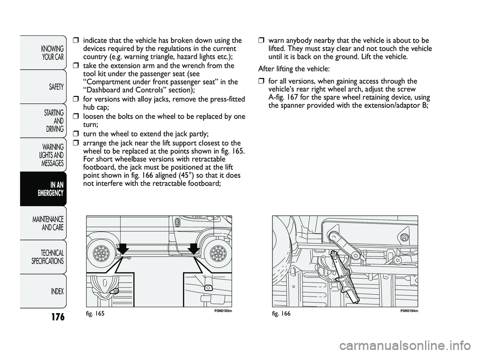
❒for all versions, when gaining access through the
vehicle’s rear right wheel arch, adjust the screw
A-fig. 167 for the spare wheel retaining device, using
the spanner provided with the extension/adaptor B;
❒indicate that the vehicle has broken down using the
devices required by the regulations in the current
country (e.g. warning triangle, hazard lights etc.);
❒take the extension arm and the wrench from the
tool kit under the passenger seat (see
“Compartment under front passenger seat” in the
“Dashboard and Controls” section);
❒for versions with alloy jacks, remove the press-fitted
hub cap;
❒loosen the bolts on the wheel to be replaced by one
turn;
❒turn the wheel to extend the jack partly;
❒arrange the jack near the lift support closest to the
wheel to be replaced at the points shown in fig. 165.
For short wheelbase versions with retractable
footboard, the jack must be positioned at the lift
point shown in fig. 166 aligned (45°) so that it does
not interfere with the retractable footboard;
173-206 DUCATO LUM EN 8ed 27-10-2010 15:45 Pagina 176
Page 178 of 286
177
KNOWING
YOUR CAR
SAFETY
STARTING
AND
DRIVING
WARNING
LIGHTS AND
MESSAGES
IN AN
EMERGENCY
MAINTENANCE
AND CARE
TECHNICAL
SPECIFICATIONS
INDEX
F0N0836mfig. 168F0N0165mfig. 169
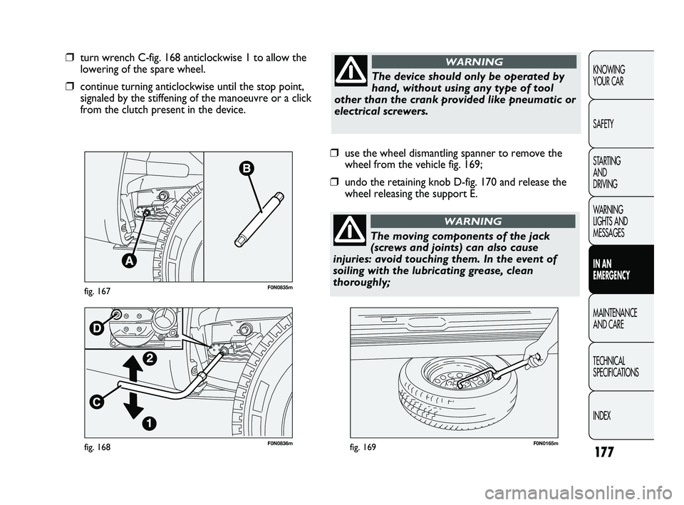
❒use the wheel dismantling spanner to remove the
wheel from the vehicle fig. 169;
❒undo the retaining knob D-fig. 170 and release the
wheel releasing the support E.
❒turn wrench C-fig. 168 anticlockwise 1 to allow the
lowering of the spare wheel.
❒continue turning anticlockwise until the stop point,
signaled by the stiffening of the manoeuvre or a click
from the clutch present in the device.
F0N0835mfig. 167
The device should only be operated by
hand, without using any type of tool
other than the crank provided like pneumatic or
electrical screwers.
WARNING
The moving components of the jack
(screws and joints) can also cause
injuries: avoid touching them. In the event of
soiling with the lubricating grease, clean
thoroughly;
WARNING
173-206 DUCATO LUM EN 8ed 27-10-2010 15:45 Pagina 177
Page 179 of 286
178
KNOWING
YOUR CAR
SAFETY
STARTING
AND
DRIVING
WARNING
LIGHTS AND
MESSAGES
IN AN
EMERGENCY
MAINTENANCE
AND CARE
TECHNICAL
SPECIFICATIONS
INDEX
F0N0370mfig. 170F0N0168mfig. 172
F0N0167mfig. 171
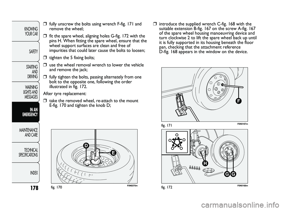
❒introduce the supplied wrench C-fig. 168 with the
suitable extension B-fig. 167 on the screw A-fig. 167
of the spare wheel housing manoeuvring device and
turn clockwise 2 to lift the spare wheel back up until
it is fully supported in its housing beneath the floor
pan, checking that the attachment reference
D-fig. 168 appears in the window on the device.❒fully unscrew the bolts using wrench F-fig. 171 and
remove the wheel;
❒fit the spare wheel, aligning holes G-fig. 172 with the
pins H. When fitting the spare wheel, ensure that the
wheel support surfaces are clean and free of
impurities that could later cause the bolts to loosen;
❒tighten the 5 fixing bolts;
❒use the wheel removal wrench to lower the vehicle
and remove the jack;
❒fully tighten the bolts, passing alternately from one
bolt to the opposite one, following the order
illustrated in fig. 172.
After tyre replacement:
❒take the removed wheel, re-attach to the mount
E-fig. 170 and tighten the knob D;
173-206 DUCATO LUM EN 8ed 27-10-2010 15:45 Pagina 178
Page 180 of 286
179
KNOWING
YOUR CAR
SAFETY
STARTING
AND
DRIVING
WARNING
LIGHTS AND
MESSAGES
IN AN
EMERGENCY
MAINTENANCE
AND CARE
TECHNICAL
SPECIFICATIONS
INDEX
F0N0251mfig. 174
F0N0837mfig. 173
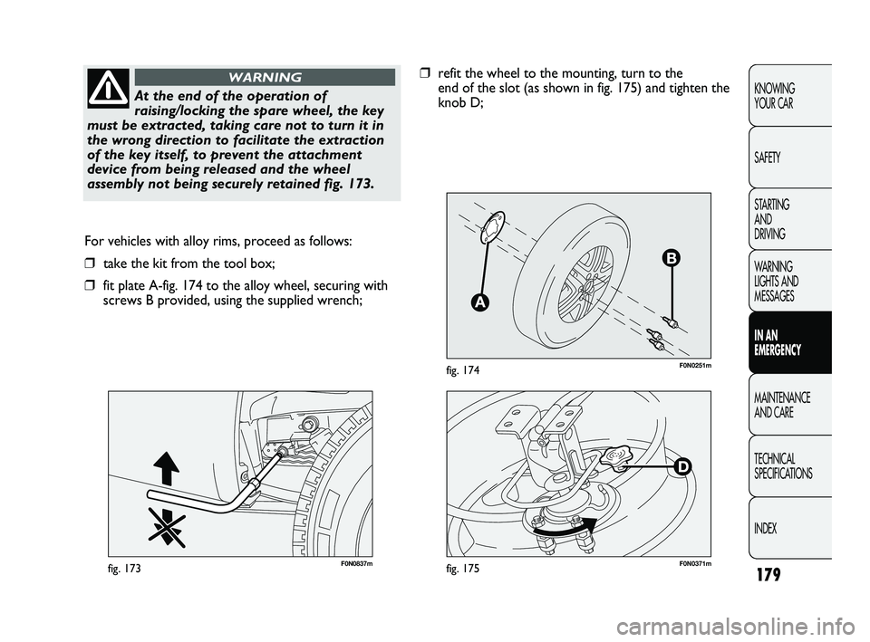
For vehicles with alloy rims, proceed as follows:
❒take the kit from the tool box;
❒fit plate A-fig. 174 to the alloy wheel, securing with
screws B provided, using the supplied wrench;
At the end of the operation of
raising/locking the spare wheel, the key
must be extracted, taking care not to turn it in
the wrong direction to facilitate the extraction
of the key itself, to prevent the attachment
device from being released and the wheel
assembly not being securely retained fig. 173.
WARNING❒refit the wheel to the mounting, turn to the
end of the slot (as shown in fig. 175) and tighten the
knob D;
F0N0371mfig. 175
173-206 DUCATO LUM EN 8ed 27-10-2010 15:45 Pagina 179