Reverse FIAT DUCATO 2013 Owner handbook (in English)
[x] Cancel search | Manufacturer: FIAT, Model Year: 2013, Model line: DUCATO, Model: FIAT DUCATO 2013Pages: 287, PDF Size: 4.5 MB
Page 17 of 287
13
KNOWING
YOUR CAR
SAFETY
STARTING
AND
DRIVING
WARNING
LIGHTS AND
MESSAGES
IN AN
EMERGENCY
MAINTENANCE
AND CARE
TECHNICAL
SPECIFICATIONS
INDEX
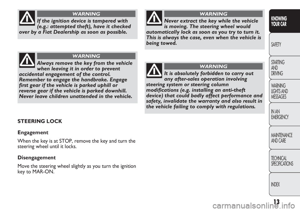
Never extract the key while the vehicle
is moving. The steering wheel would
automatically lock as soon as you try to turn it.
This is always the case, even when the vehicle is
being towed.
WARNING
It is absolutely forbidden to carry out
any after-sales operation involving
steering system or steering column
modifications (e.g. installing an anti-theft
device) that could badly affect performance and
safety, invalidate the warranty and also result in
the vehicle failing to comply with regulations.
WARNING
If the ignition device is tampered with
(e.g.: attempted theft), have it checked
over by a Fiat Dealership as soon as possible.
WARNING
Always remove the key from the vehicle
when leaving it in order to prevent
accidental engagement of the control.
Remember to engage the handbrake. Engage
first gear if the vehicle is parked uphill or
reverse gear if the vehicle is parked downhill.
Never leave children unattended in the vehicle.
WARNING
STEERING LOCK
Engagement
When the key is at STOP, remove the key and turn the
steering wheel until it locks.
Disengagement
Move the steering wheel slightly as you turn the ignition
key to MAR-ON.
Page 78 of 287
74
KNOWING
YOUR CAR
SAFETY
STARTING
AND
DRIVING
WARNING
LIGHTS AND
MESSAGES
IN AN
EMERGENCY
MAINTENANCE
AND CARE
TECHNICAL
SPECIFICATIONS
INDEX
When travelling downhill with the device engaged, the
vehicle speed may slightly exceed the memorised one.
When the device is activated the warning light
Ücomes
on together with the relevant message on the
instrument panel.
STORING VEHICLE SPEED
Proceed as follows:
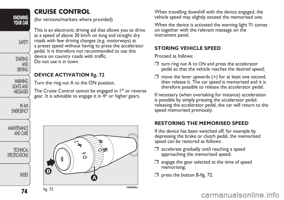
❒turn ring nut A toONand press the accelerator
pedal so that the vehicle reaches the desired speed;
❒move the lever upwards (+) for at least one second,
then release it. The car speed is memorised and it is
therefore possible to release the accelerator pedal.
If necessary (when overtaking for instance) acceleration
is possible by simply pressing the accelerator pedal:
releasing the accelerator pedal, the car will return to the
speed memorised previously.
RESTORING THE MEMORISED SPEED
If the device has been switched off, for example by
depressing the brake or clutch pedal, the memorised
speed can be restored as follows:
❒accelerate gradually until reaching a speed
approaching the memorised speed;
❒engage the gear selected at the time of speed
memorising;
❒press the button B-fig. 72.
F0N0508mfig. 72
CRUISE CONTROL
(for versions/markets where provided)
This is an electronic driving aid that allows you to drive
at a speed of above 30 km/h on long and straight dry
roads with few driving changes (e.g. motorways) at
a preset speed without having to press the accelerator
pedal. It is therefore not recommended to use this
device on country roads with traffic.
Do not use it in town.
DEVICE ACTIVATION fig. 72
Turn the ring nut A to the ON position.
The Cruise Control cannot be engaged in 1
stor reverse
gear. It is advisable to engage it in 4thor higher gears.
Page 96 of 287
92
KNOWING
YOUR CAR
SAFETY
STARTING
AND
DRIVING
WARNING
LIGHTS AND
MESSAGES
IN AN
EMERGENCY
MAINTENANCE
AND CARE
TECHNICAL
SPECIFICATIONS
INDEX
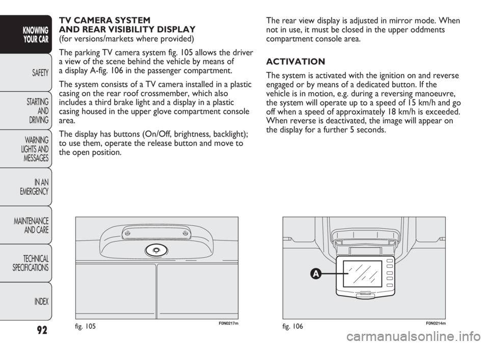
F0N0217mfig. 105F0N0214mfig. 106
The rear view display is adjusted in mirror mode. When
not in use, it must be closed in the upper oddments
compartment console area.
ACTIVATION
The system is activated with the ignition on and reverse
engaged or by means of a dedicated button. If the
vehicle is in motion, e.g. during a reversing manoeuvre,
the system will operate up to a speed of 15 km/h and go
off when a speed of approximately 18 km/h is exceeded.
When reverse is deactivated, the image will appear on
the display for a further 5 seconds. TV CAMERA SYSTEM
AND REAR VISIBILITY DISPLAY
(for versions/markets where provided)
The parking TV camera system fig. 105 allows the driver
a view of the scene behind the vehicle by means of
a display A-fig. 106 in the passenger compartment.
The system consists of a TV camera installed in a plastic
casing on the rear roof crossmember, which also
includes a third brake light and a display in a plastic
casing housed in the upper glove compartment console
area.
The display has buttons (On/Off, brightness, backlight);
to use them, operate the release button and move to
the open position.
Page 98 of 287
94
KNOWING
YOUR CAR
SAFETY
STARTING
AND
DRIVING
WARNING
LIGHTS AND
MESSAGES
IN AN
EMERGENCY
MAINTENANCE
AND CARE
TECHNICAL
SPECIFICATIONS
INDEX
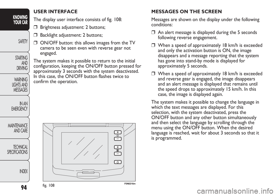
F0N0216mfig. 108
MESSAGES ON THE SCREEN
Messages are shown on the display under the following
conditions:
❒An alert message is displayed during the 5 seconds
following reverse engagement.
❒When a speed of approximately 18 km/h is exceeded
and only the activation button is ON, the image
disappears and a message reporting that the system
has gone into stand-by mode is displayed for
approximately 5 seconds.
❒When a speed of approximately 18 km/h is exceeded
and reverse gear is engaged, the image disappears
and an alert message is displayed that remains until
the speed drops to approximately 15 km/h. In this
case, the image is displayed again.
The system makes it possible to change the language in
which the text messages are displayed. For this
selection, with the system deactivated, press the
ON/OFF button and any other button simultaneously
and then select the language by scrolling through the
menu using the ON/OFF button. When the desired
language is reached, wait for about 3 seconds so that it
is programmed. USER INTERFACE
The display user interface consists of fig. 108:
❒Brightness adjustment: 2 buttons;
❒Backlight adjustment: 2 buttons;
❒ON/OFF button: this allows images from the TV
camera to be seen even with reverse gear not
engaged.
The system makes it possible to return to the initial
configuration, keeping the ON/OFF button pressed for
approximately 3 seconds with the system deactivated.
In this case, the ON/OFF button flashes twice to
confirm the operation.
Page 115 of 287
111
KNOWING
YOUR CAR
SAFETY
STARTING
AND
DRIVING
WARNING
LIGHTS AND
MESSAGES
IN AN
EMERGENCY
MAINTENANCE
AND CARE
TECHNICAL
SPECIFICATIONS
INDEX
❒downhill: vehicle stationary on a road with a gradient
higher than 5%, engine running, clutch and brake
pedal pressed and reverse gear engaged.
At pickup the
ESPsystem control unit will maintain the
braking pressure at the wheels until the necessary torque
for starting is reached or, in any case, for a maximum of
2 seconds in order to move easily from the brake pedal
to the accelerator pedal. When two seconds have
elapsed, without starting, the system is automatically
deactivated, gradually releasing the braking pressure.
During this release stage, the typical brake
disengagement noise indicating that the vehicle is going
to move imminently will be heard.
Failure warning
The
áwarning light in the instrument panel will come
on in the event of a failure (see “Warning lights and
messages” section).
IMPORTANT The Hill Holder system is not a parking
brake; therefore, never leave the vehicle without having
engaged the handbrake, turned the engine off and
engaged first gear. FAILURE WARNING
In the event of a failure, the ESP will be automatically
switched off and the áwarning light will come on
constantly in the instrument panel along with a message
in the multifunction display (for versions/markets where
provided) (see “Warning lights and messages” section).
The LED in the ASR OFF button will light up. Contact
a Fiat Dealership as soon as possible if this happens.
Do not take unnecessary risks, even if
your vehicle is fitted with an ESP system.
Your driving style must always be suited to the
road conditions, visibility and traffic. The driver
is ultimately responsible for road safety.
WARNING
HILL HOLDER SYSTEM
This system is an integral part of the
ESPsystem and it is
provided to facilitate starting on hills.
It is automatically activated in the following conditions:
❒uphill: vehicle stationary on a road with a gradient
higher than 5%, engine running, clutch and brake
pedal pressed, gearbox in neutral or gear other than
reverse engaged;
For the correct operation of the ESP and
ASR systems, the tyres must absolutely be
the same make and type on all wheels, in perfect
condition and, above all, of the type, make and
size specified.
WARNING
Page 120 of 287
F0N0119mfig. 131
PARKING SENSORS
(for versions/markets where provided)
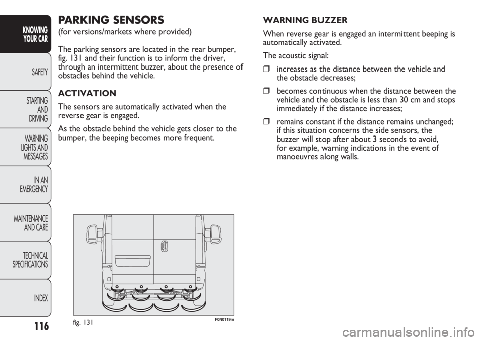
The parking sensors are located in the rear bumper,
fig. 131 and their function is to inform the driver,
through an intermittent buzzer, about the presence of
obstacles behind the vehicle.
ACTIVATION
The sensors are automatically activated when the
reverse gear is engaged.
As the obstacle behind the vehicle gets closer to the
bumper, the beeping becomes more frequent. WARNING BUZZER
When reverse gear is engaged an intermittent beeping is
automatically activated.
The acoustic signal:
❒increases as the distance between the vehicle and
the obstacle decreases;
❒becomes continuous when the distance between the
vehicle and the obstacle is less than 30 cm and stops
immediately if the distance increases;
❒remains constant if the distance remains unchanged;
if this situation concerns the side sensors, the
buzzer will stop after about 3 seconds to avoid,
for example, warning indications in the event of
manoeuvres along walls.
116
KNOWING
YOUR CAR
SAFETY
STARTING
AND
DRIVING
WARNING
LIGHTS AND
MESSAGES
IN AN
EMERGENCY
MAINTENANCE
AND CARE
TECHNICAL
SPECIFICATIONS
INDEX
Page 121 of 287
117
KNOWING
YOUR CAR
SAFETY
STARTING
AND
DRIVING
WARNING
LIGHTS AND
MESSAGES
IN AN
EMERGENCY
MAINTENANCE
AND CARE
TECHNICAL
SPECIFICATIONS
INDEX
Detection distances
Central action range: 140 cm ±10 cm
Side action range: 60 cm ±20 cm
If several obstacles are detected by the sensors, only the
nearest one is considered.
FAILURE WARNING
Any parking sensor failures will be indicated when
engaging reverse by the
twarning light in the instrument
panel together with the message in the multifunction
display coming on for versions/markets where provided
(see “Warning lights and messages” section).OPERATION WITH TRAILER
Parking sensor operation is automatically disabled when
the electric cable plug of the trailer is fitted into the
vehicle tow hook socket.
The sensors are automatically enabled again when the
trailer cable plug is removed.
IMPORTANT If you wish to leave the tow hook fitted
without towing a trailer, it is advisable to contact a Fiat
Dealership for the relevant system update operations
because the tow hook could be detected as an obstacle
by the central sensors.
When using special washing equipment such as high
pressure jets or steam cleaning, clean the sensors very
quickly keeping the jet more than 10 cm away.
Page 149 of 287
145
KNOWING
YOUR CAR
SAFETY
STARTING
AND
DRIVING
WARNING
LIGHTS AND
MESSAGES
IN AN
EMERGENCY
MAINTENANCE
AND CARE
TECHNICAL
SPECIFICATIONS
INDEX
F0N0073mfig. 154
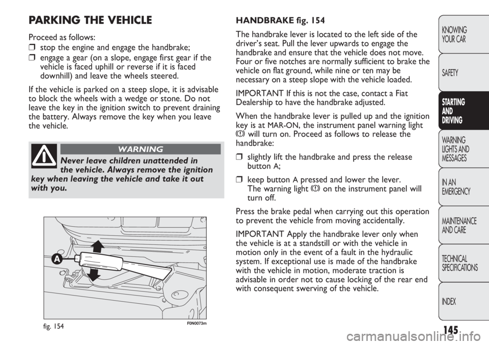
HANDBRAKE fig. 154
The handbrake lever is located to the left side of the
driver’s seat. Pull the lever upwards to engage the
handbrake and ensure that the vehicle does not move.
Four or five notches are normally sufficient to brake the
vehicle on flat ground, while nine or ten may be
necessary on a steep slope with the vehicle loaded.
IMPORTANT If this is not the case, contact a Fiat
Dealership to have the handbrake adjusted.
When the handbrake lever is pulled up and the ignition
key is at
MAR-ON, the instrument panel warning light
xwill turn on. Proceed as follows to release the
handbrake:
❒slightly lift the handbrake and press the release
button
A;
❒keep button Apressed and lower the lever.
The warning light
xon the instrument panel will
turn off.
Press the brake pedal when carrying out this operation
to prevent the vehicle from moving accidentally.
IMPORTANT Apply the handbrake lever only when
the vehicle is at a standstill or with the vehicle in
motion only in the event of a fault in the hydraulic
system. If exceptional use is made of the handbrake
with the vehicle in motion, moderate traction is
advisable in order not to cause locking of the rear end
with consequent swerving of the vehicle.
PARKING THE VEHICLE
Proceed as follows:
❒stop the engine and engage the handbrake;
❒engage a gear (on a slope, engage first gear if the
vehicle is faced uphill or reverse if it is faced
downhill) and leave the wheels steered.
If the vehicle is parked on a steep slope, it is advisable
to block the wheels with a wedge or stone. Do not
leave the key in the ignition switch to prevent draining
the battery. Always remove the key when you leave
the vehicle.
Never leave children unattended in
the vehicle. Always remove the ignition
key when leaving the vehicle and take it out
with you.
WARNING
Page 150 of 287
146
KNOWING
YOUR CAR
SAFETY
STARTING
AND
DRIVING
WARNING
LIGHTS AND
MESSAGES
IN AN
EMERGENCY
MAINTENANCE
AND CARE
TECHNICAL
SPECIFICATIONS
INDEX
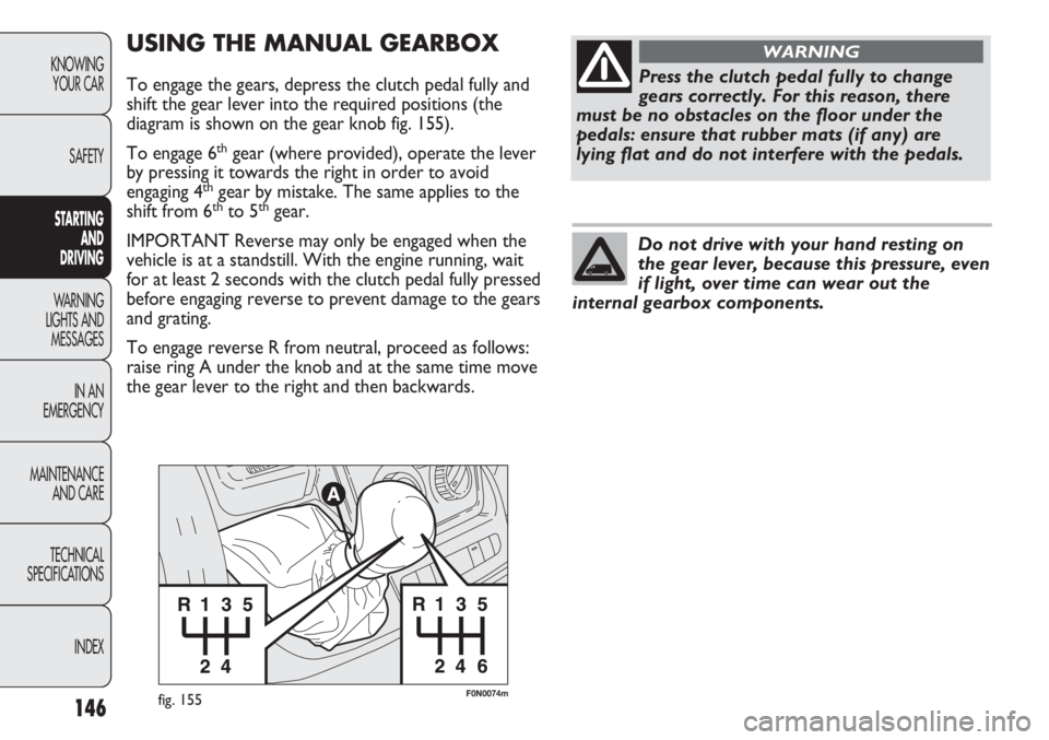
F0N0074mfig. 155
USING THE MANUAL GEARBOX
To engage the gears, depress the clutch pedal fully and
shift the gear lever into the required positions (the
diagram is shown on the gear knob fig. 155).
To engage 6
thgear (where provided), operate the lever
by pressing it towards the right in order to avoid
engaging 4
thgear by mistake. The same applies to the
shift from 6thto 5thgear.
IMPORTANT Reverse may only be engaged when the
vehicle is at a standstill. With the engine running, wait
for at least 2 seconds with the clutch pedal fully pressed
before engaging reverse to prevent damage to the gears
and grating.
To engage reverse R from neutral, proceed as follows:
raise ring A under the knob and at the same time move
the gear lever to the right and then backwards.
Press the clutch pedal fully to change
gears correctly. For this reason, there
must be no obstacles on the floor under the
pedals: ensure that rubber mats (if any) are
lying flat and do not interfere with the pedals.
WARNING
Do not drive with your hand resting on
the gear lever, because this pressure, even
if light, over time can wear out the
internal gearbox components.
Page 174 of 287
170
KNOWING
YOUR CAR
SAFETY
STARTING
AND
DRIVING
WARNING
LIGHTS AND
MESSAGES
IN AN
EMERGENCY
MAINTENANCE
AND CARE
TECHNICAL
SPECIFICATIONS
INDEX
REPLACING A WHEEL
GENERAL INSTRUCTIONS
Wheel changing and correct use of the jack and spare
wheel (for versions/markets where provided) call for
some precautions, which are listed below. Proceed as follows to start the car:
❒raise the flap A to gain access to the positive battery
terminal fig. 157.
❒connect the positive terminals (+ sign near the
terminal) of the two batteries with a jump lead;
❒connect the negative terminal (–) of the auxiliary
battery to the earth point with a second cable as
shown in fig. 158;
❒Start the engine;
❒when the engine has been started, follow the
sequence above in reverse order to remove the
leads.
If after a few attempts the engine does not start, do not
persist but contact the nearest Fiat Dealership.
IMPORTANT Do not directly connect the negative
terminals of the two batteries: any sparks may ignite the
explosive gas which could come out of the battery.
If the auxiliary battery is installed on another vehicle,
prevent any metal parts on the latter and the vehicle
with the flat battery from accidentally coming into
contact.
BUMP STARTING
Never bump start the engine by pushing, towing or
driving downhill. This could cause a flow of fuel into the
catalytic converter and damage it beyond repair.
IMPORTANT Remember that the brake servo and the
power steering system are not activated until the engine
is started, a greater effort will therefore be required to
press the brake pedal or turn the steering wheel.Indicate that the vehicle is stationary
according to the regulations in force:
emergency lights, refracting warning triangle,
etc. Passengers should leave the vehicle,
particularly if it is very loaded, and wait for the
wheel to be changed away from on-coming
traffic. Apply the handbrake.
WARNING
The spare wheel (for versions/markets
where provided) is specific for your
vehicle. Therefore, it must not be used on
vehicles of a different model. Do not use spare
wheels of different models on your vehicle. The
wheel bolts are specific to your vehicle: do not
use them on other models and do not use bolts
of other models.
WARNING