handbrake FIAT DUCATO 2014 Owner handbook (in English)
[x] Cancel search | Manufacturer: FIAT, Model Year: 2014, Model line: DUCATO, Model: FIAT DUCATO 2014Pages: 367, PDF Size: 20.39 MB
Page 191 of 367
SNOW CHAINSThe use of snow chains should be in
compliance with local regulations of
each country.
Snow chains can be fitted to the tyres
of the front wheels (drive wheels) only.
Use of Lineaccessori Fiat snow chains
is recommended. Check the tension
of the snow chains after the first few
metres have been driven.
42)
IMPORTANT With snow chains, use the
accelerator with extreme care to
prevent, or to limit as much as possible,
slipping of the drive wheels that could
cause chain breakage, resulting in
damage to the car body or mechanical
components.
IMPORTANT For versions fitted with
225/75 R16 tyre, use snow chains with
max. thickness 16 mm.
When travelling on snowy roads with
snow chains, it may be helpful to turn
the ASR off: in fact, in these conditions,
the driving wheels skidding when
moving off gives you better traction.
IMPORTANT
42) Keep your speed down when
snow chains are fitted; do not
exceed 50 km/h. Avoid potholes,
steps and pavements and avoid
driving for long distances on
roads not covered with snow to
prevent damaging the vehicle and
the roadbed.
PROLONGED
VEHICLE INACTIVITYIf the vehicle needs to be off the road
for longer than one month, the following
precautions must be taken:
❒park the vehicle indoors in a dry and,
if possible, well-ventilated place;
❒engage a gear;
❒check that the handbrake is not
engaged;
❒disconnect the negative battery
terminal; if the vehicle is equipped
with a battery disconnection function
(disconnector), see the description
of the procedure in the "Controls"
paragraph in the "Dashboard and
controls" section;
❒clean and protect the painted parts
using protective wax;
❒clean and protect the shiny metal
parts using special compounds
available commercially;
❒sprinkle talcum powder on the
windscreen and rear window wiper
rubber blades and lift them off the
glass;
❒slightly open the windows;
187
Page 195 of 367
BUMP STARTING
Never bump start the engine by
pushing, towing or driving downhill.
This could cause fuel to flow into the
catalytic converter and damage it
beyond repair.
WARNING
136) This procedure must be
performed by qualified personnel
as incorrect actions may cause
high-intensity electrical discharge.
Furthermore, battery fluid is
poisonous and corrosive: avoid
contact with skin and eyes. Keep
naked flames and lighted
cigarettes away from the battery
and do not cause sparks.
REPLACING A
WHEELGENERAL
INSTRUCTIONS
Wheel replacement and correct use of
the jack and spare wheel (for
versions/markets, where provided) call
for some precautions, which are listed
below.
137) 138) 139) 140) 141)
Please note that:
❒the jack weight is 4.5 kg;
❒the jack requires no adjustment;
❒the jack cannot be repaired: in the
event of a fault it must be replaced by
another original one;
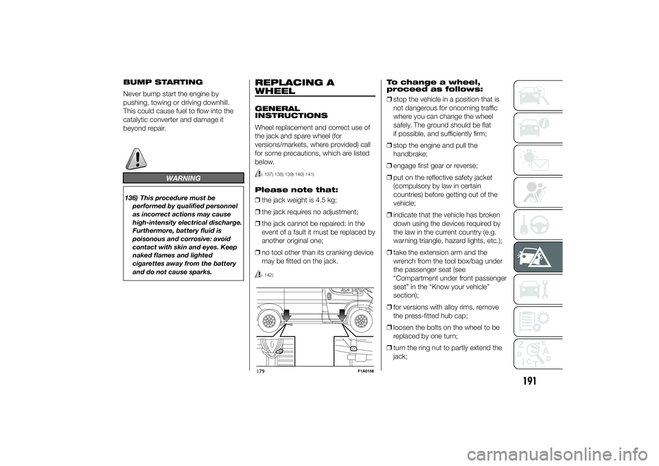
❒no tool other than its cranking device
may be fitted on the jack.
142)
To change a wheel,
proceed as follows:
❒stop the vehicle in a position that is
not dangerous for oncoming traffic
where you can change the wheel
safely. The ground should be flat
if possible, and sufficiently firm;
❒stop the engine and pull the
handbrake;
❒engage first gear or reverse;
❒put on the reflective safety jacket
(compulsory by law in certain
countries) before getting out of the
vehicle;
❒indicate that the vehicle has broken
down using the devices required by
the law in the current country (e.g.
warning triangle, hazard lights, etc.);
❒take the extension arm and the
wrench from the tool box/bag under
the passenger seat (see
“Compartment under front passenger
seat” in the “Know your vehicle”
section);
❒for versions with alloy rims, remove
the press-fitted hub cap;
❒loosen the bolts on the wheel to be
replaced by one turn;
❒turn the ring nut to partly extend the
jack;
179
F1A0168
191
Page 198 of 367
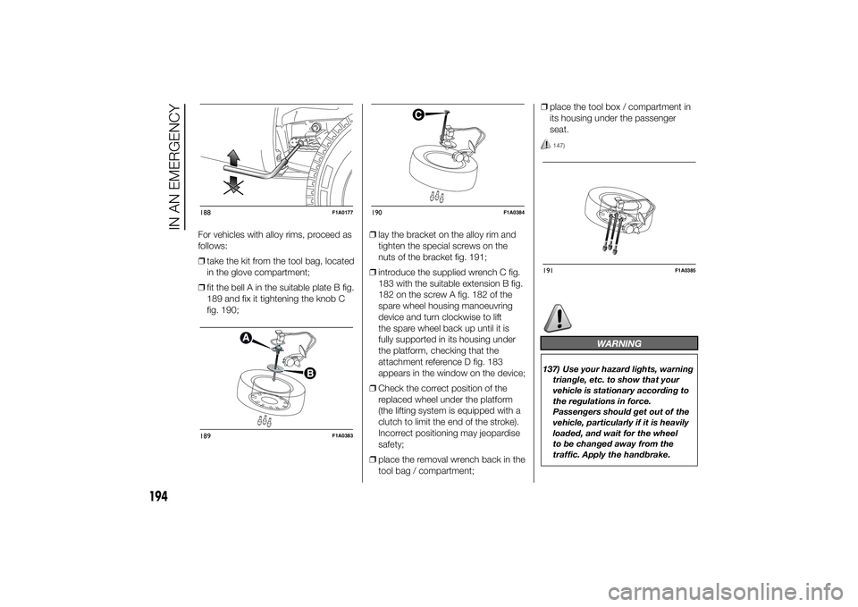
For vehicles with alloy rims, proceed as
follows:
❒take the kit from the tool bag, located
in the glove compartment;
❒fit the bell A in the suitable plate B fig.
189 and fix it tightening the knob C
fig. 190;❒lay the bracket on the alloy rim and
tighten the special screws on the
nuts of the bracket fig. 191;
❒introduce the supplied wrench C fig.
183 with the suitable extension B fig.
182 on the screw A fig. 182 of the
spare wheel housing manoeuvring
device and turn clockwise to lift
the spare wheel back up until it is
fully supported in its housing under
the platform, checking that the
attachment reference D fig. 183
appears in the window on the device;
❒Check the correct position of the
replaced wheel under the platform
(the lifting system is equipped with a
clutch to limit the end of the stroke).
Incorrect positioning may jeopardise
safety;
❒place the removal wrench back in the
tool bag / compartment;❒place the tool box / compartment in
its housing under the passenger
seat.
147)
WARNING
137) Use your hazard lights, warning
triangle, etc. to show that your
vehicle is stationary according to
the regulations in force.
Passengers should get out of the
vehicle, particularly if it is heavily
loaded, and wait for the wheel
to be changed away from the
traffic. Apply the handbrake.
188
F1A0177
189
F1A0383
190
F1A0384
191
F1A0385
194
IN AN EMERGENCY
Page 200 of 367
FIX&GO
AUTOMATIC QUICK
TYRE REPAIR KIT(for versions/markets, where provided)
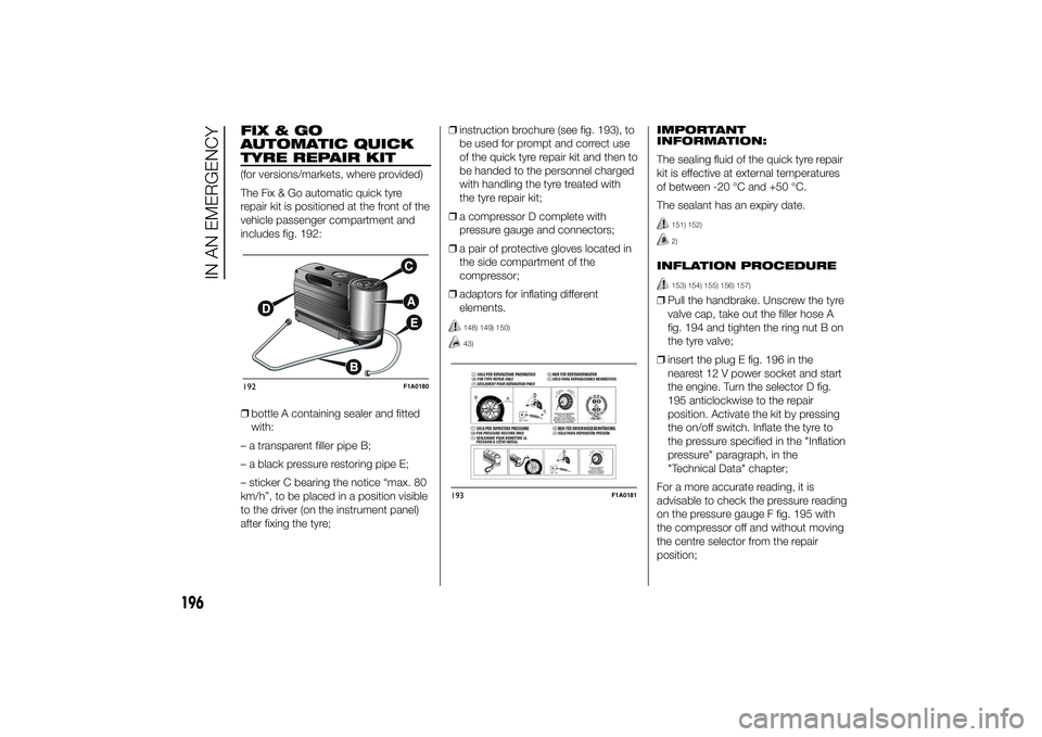
The Fix & Go automatic quick tyre
repair kit is positioned at the front of the
vehicle passenger compartment and
includes fig. 192:
❒bottle A containing sealer and fitted
with:
– a transparent filler pipe B;
– a black pressure restoring pipe E;
– sticker C bearing the notice “max. 80
km/h”, to be placed in a position visible
to the driver (on the instrument panel)
after fixing the tyre;❒instruction brochure (see fig. 193), to
be used for prompt and correct use
of the quick tyre repair kit and then to
be handed to the personnel charged
with handling the tyre treated with
the tyre repair kit;
❒a compressor D complete with
pressure gauge and connectors;
❒a pair of protective gloves located in
the side compartment of the
compressor;
❒adaptors for inflating different
elements.
148) 149) 150)43)
IMPORTANT
INFORMATION:
The sealing fluid of the quick tyre repair
kit is effective at external temperatures
of between -20 °C and +50 °C.
The sealant has an expiry date.
151) 152)2)
INFLATION PROCEDURE
153) 154) 155) 156) 157)
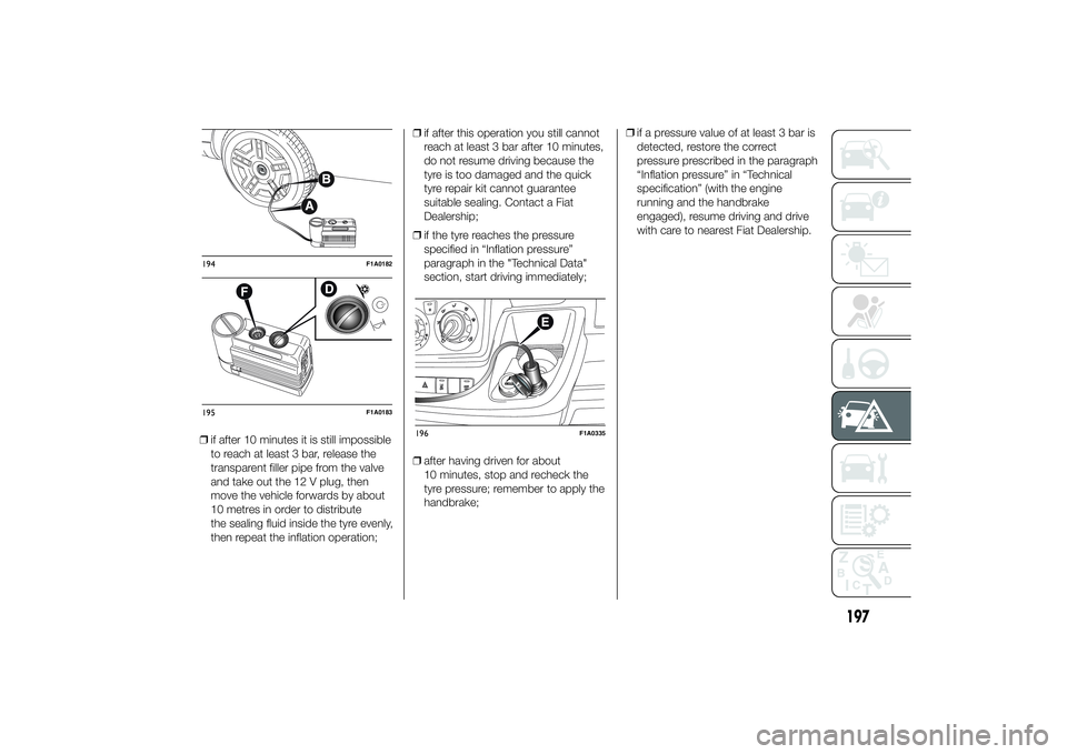
❒Pull the handbrake. Unscrew the tyre
valve cap, take out the filler hose A
fig. 194 and tighten the ring nut B on
the tyre valve;
❒insert the plug E fig. 196 in the
nearest 12 V power socket and start
the engine. Turn the selector D fig.
195 anticlockwise to the repair
position. Activate the kit by pressing
the on/off switch. Inflate the tyre to
the pressure specified in the "Inflation
pressure" paragraph, in the
"Technical Data" chapter;
For a more accurate reading, it is
advisable to check the pressure reading
on the pressure gauge F fig. 195 with
the compressor off and without moving
the centre selector from the repair
position;
192
F1A0180
193
F1A0181
196
IN AN EMERGENCY
Page 201 of 367
❒if after 10 minutes it is still impossible
to reach at least 3 bar, release the
transparent filler pipe from the valve
and take out the 12 V plug, then
move the vehicle forwards by about
10 metres in order to distribute
the sealing fluid inside the tyre evenly,
then repeat the inflation operation;❒if after this operation you still cannot
reach at least 3 bar after 10 minutes,
do not resume driving because the
tyre is too damaged and the quick
tyre repair kit cannot guarantee
suitable sealing. Contact a Fiat
Dealership;
❒if the tyre reaches the pressure
specified in “Inflation pressure”
paragraph in the "Technical Data"
section, start driving immediately;
❒after having driven for about
10 minutes, stop and recheck the
tyre pressure; remember to apply the
handbrake;❒if a pressure value of at least 3 bar is
detected, restore the correct
pressure prescribed in the paragraph
“Inflation pressure” in “Technical
specification” (with the engine
running and the handbrake
engaged), resume driving and drive
with care to nearest Fiat Dealership.194
F1A0182
195
F1A0183
196
F1A0335
197
Page 202 of 367
FOR CHECKING AND
RESTORING PRESSURE
ONLY
The compressor can also be used
solely for restoring pressure.
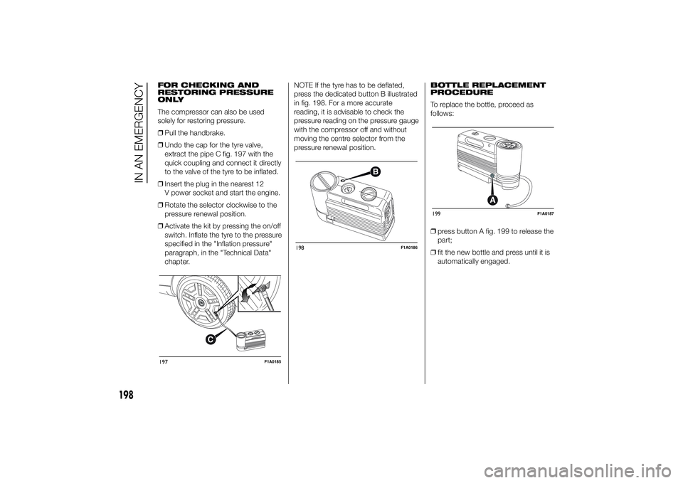
❒Pull the handbrake.
❒Undo the cap for the tyre valve,
extract the pipe C fig. 197 with the
quick coupling and connect it directly
to the valve of the tyre to be inflated.
❒Insert the plug in the nearest 12
V power socket and start the engine.
❒Rotate the selector clockwise to the
pressure renewal position.
❒Activate the kit by pressing the on/off
switch. Inflate the tyre to the pressure
specified in the "Inflation pressure"
paragraph, in the "Technical Data"
chapter.NOTE If the tyre has to be deflated,
press the dedicated button B illustrated
in fig. 198. For a more accurate
reading, it is advisable to check the
pressure reading on the pressure gauge
with the compressor off and without
moving the centre selector from the
pressure renewal position.BOTTLE REPLACEMENT
PROCEDURE
To replace the bottle, proceed as
follows:
❒press button A fig. 199 to release the
part;
❒fit the new bottle and press until it is
automatically engaged.197
F1A0185
198
F1A0186
199
F1A0187
198
IN AN EMERGENCY
Page 230 of 367
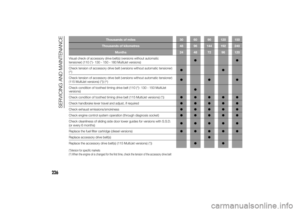
Thousands of miles 30 60 90 120 150
Thousands of kilometres 48 96 144 192 240
Months 24 48 72 96 120
Visual check of accessory drive belt(s) (versions without automatic
tensioner) (110 (°)- 130 - 150 - 180 MultiJet versions)●●
Check tension of accessory drive belt (versions without automatic tensioner)
(^)●●
Check tension of accessory drive belt (versions without automatic tensioner)
(115 MultiJet versions) (°)) (^)●●●
Check condition of toothed timing drive belt (110 (°)- 130 - 150 MultiJet
versions)●
Check condition of toothed timing drive belt (115 MultiJet versions) (°))●●●●●
Check handbrake lever travel and adjust, if required●●●●●
Check exhaust emissions/smokiness●●●●●
Check engine control system operation (through diagnosis socket)●●●●●
Check cleanliness of sliding side door lower guides for versions with S.S.D.
(or every 6 months)●●●●●
Replace the fuel filter cartridge (diesel versions)●●●●●
Replace accessory drive belt(s)●
Replace the accessory drive belt(s) (115 MultiJet versions) (°))●●(°)Version for specific markets
(^) When the engine oil is changed for the first time, check the tension of the accessory drive belt
226
SERVICING AND MAINTENANCE
Page 250 of 367
INTERIORSRegularly check that water is not
trapped under the mats (due to water
dripping off shoes, umbrellas, etc.),
as this could cause oxidation of the
sheet metal.
193) 194)
SEATS AND FABRIC
PARTS
Remove dust with a soft brush or a
vacuum cleaner. It is advisable to use a
moist brush on velvet upholstery.
Rub the seats with a sponge moistened
with a solution of water and mild soap.PLASTIC PARTS
It is advisable to clean interior parts with
a moist cloth and a solution of water
and non-abrasive mild soap. Use
specific products for cleaning plastic,
without solvents and specifically
designed to prevent damage to the
appearance and colour of the treated
parts, to remove grease and tough
stains.
IMPORTANT Do not use alcohol,
petrols or derivatives to clean
the instrument panel glass.LEATHER STEERING
WHEEL/GEAR
KNOB/HANDBRAKE
(for versions/markets, where provided)
These components must be cleaned
with mild soap and water only. Never
use alcohol or alcohol-based products.
Read the product label carefully before
using specific products for cleaning
the interiors: make sure that the
product does not contain spirits or
alcohol-based substances.
If, when cleaning the windscreen with
special products, window cleaner
accidentally drips onto the leather of
the steering wheel/gear lever
knob/handbrake, wipe away
immediately and then wash the affected
area with mild soap and water.
IMPORTANT Be careful when using a
steering wheel lock device, where
applicable, to avoid damaging
the leather upholstery by rubbing.
246
SERVICING AND MAINTENANCE