lights FIAT DUCATO 2014 Owner handbook (in English)
[x] Cancel search | Manufacturer: FIAT, Model Year: 2014, Model line: DUCATO, Model: FIAT DUCATO 2014Pages: 367, PDF Size: 20.39 MB
Page 145 of 367
What it means What to do
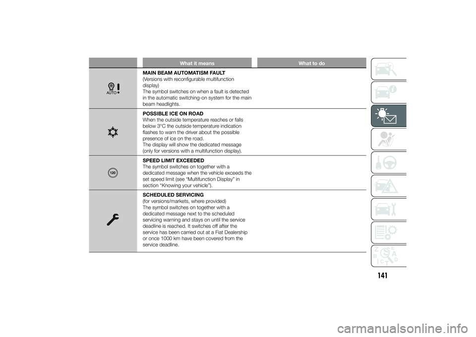
MAIN BEAM AUTOMATISM FAULT
(Versions with reconfigurable multifunction
display)
The symbol switches on when a fault is detected
in the automatic switching-on system for the main
beam headlights.POSSIBLE ICE ON ROAD
When the outside temperature reaches or falls
below 3°C the outside temperature indication
flashes to warn the driver about the possible
presence of ice on the road.
The display will show the dedicated message
(only for versions with a multifunction display).SPEED LIMIT EXCEEDED
The symbol switches on together with a
dedicated message when the vehicle exceeds the
set speed limit (see “Multifunction Display” in
section “Knowing your vehicle”).SCHEDULED SERVICING
(for versions/markets, where provided)
The symbol switches on together with a
dedicated message next to the scheduled
servicing warning and stays on until the service
deadline is reached. It switches off after the
service has been carried out at a Fiat Dealership
or once 1000 km have been covered from the
service deadline.
141
Page 146 of 367
What it means What to do
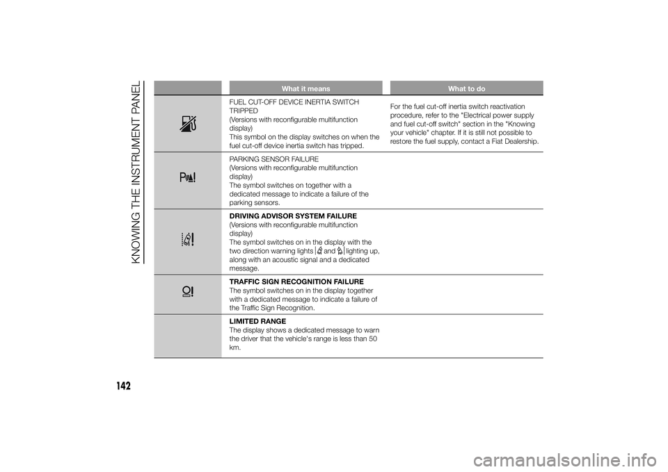
FUEL CUT-OFF DEVICE INERTIA SWITCH
TRIPPED
(Versions with reconfigurable multifunction
display)
This symbol on the display switches on when the
fuel cut-off device inertia switch has tripped.For the fuel cut-off inertia switch reactivation
procedure, refer to the "Electrical power supply
and fuel cut-off switch" section in the "Knowing
your vehicle" chapter. If it is still not possible to
restore the fuel supply, contact a Fiat Dealership.PARKING SENSOR FAILURE
(Versions with reconfigurable multifunction
display)
The symbol switches on together with a
dedicated message to indicate a failure of the
parking sensors.DRIVING ADVISOR SYSTEM FAILURE
(Versions with reconfigurable multifunction
display)
The symbol switches on in the display with the
two direction warning lights
and
lighting up,
along with an acoustic signal and a dedicated
message.
TRAFFIC SIGN RECOGNITION FAILURE
The symbol switches on in the display together
with a dedicated message to indicate a failure of
the Traffic Sign Recognition.
LIMITED RANGE
The display shows a dedicated message to warn
the driver that the vehicle's range is less than 50
km.
142
KNOWING THE INSTRUMENT PANEL
Page 174 of 367
STARTING THE
ENGINEThe vehicle is fitted with an electronic
engine lock device: if the engine fails to
start, see the paragraph “The Fiat
CODE system” in section “Know your
vehicle”.
26) 27)125)
PROCEDURE
Proceed as follows:
❒engage the handbrake;
❒put the gear lever into neutral;
❒turn the ignition key to MAR-ON: the
warning lights
and
on the
instrument panel will turn on;
❒wait for the warning lightsand
to switch off. The hotter the
engine is, the quicker this will
happen;
❒fully press the clutch pedal without
touching the accelerator;
❒turn the ignition key to AVV as soon
as warning light
switches off.
Waiting too long will waste the
heating work carried out by the glow
plugs.
Release the key as soon as the engine
starts.If the engine does not start at the first
attempt, return the ignition key to STOP
before repeating the starting procedure.
If, when the ignition key is at MAR-ON
the
warning light remains lit, turn
the key to STOP and then back to
MAR-ON; if the warning light remains
lit, try with the other keys provided with
the car.
IMPORTANT Go to a Fiat Dealership
immediately if warning light
stays
on constantly on the instrument panel.
IMPORTANT Never leave the ignition
key in MAR-ON position when the
engine is stopped.
28)
WARMING UP THE
ENGINE JUST AFTER IT
HAS STARTED
Proceed as follows:
❒drive off slowly, letting the engine turn
at medium revs. Do not accelerate
abruptly;
❒do not demand full performance at
first. Wait until the engine coolant
temperature gauge starts moving.
29) 30)
170
STARTING AND DRIVING
Page 180 of 367
SAVING FUELSome useful tips are given below for
fuel saving and reducing harmful
emissions of CO2 and other pollutants
(nitrogen oxides, unburnt
hydrocarbons, Particulate Matter (PM),
etc.).
GENERAL
CONSIDERATIONS
The general factors that affect fuel
consumption are listed below.
Vehicle maintenance
Have checks and adjustments carried
out in accordance with the “Scheduled
Servicing Plan”.Tyres
Check the tyre pressures at least once
every four weeks: if the pressure is
too low, consumption levels increase as
resistance to rolling is higher.
Unnecessary loads
Do not travel with an overloaded
luggage compartment. The weight of
the vehicle (especially when driving
in town) and its geometry greatly affect
fuel consumption and stability.
Roof rack/ski rack
Remove the roof rack or the ski rack
from the roof after use. These
accessories decrease aerodynamic
penetration of the vehicle and have a
negative effect on fuel consumption.
When transporting particularly large
objects, use a trailer if possible.Electric devices
Use electrical devices only for the
amount of time needed. The heated
rear window, additional headlights,
windscreen/rear window wipers and
heater fan need a considerable amount
of energy, therefore increasing fuel
consumption (by up to 25% in
the urban cycle).
Climate control system
Air conditioning leads to higher fuel
consumption (on average up to +20%).
If the temperature outside permits, try
and use the ventilation only.
Devices for
aerodynamic control
The use of non-certified spoilers may
adversely affect air drag and fuel
consumption.
176
STARTING AND DRIVING
Page 181 of 367
DRIVING STYLE
The main driving styles that affect fuel
consumption are listed below.
Cranking
Do not warm up the engine at low or
high revs when the vehicle is stationary;
this causes the engine to warm up
more slowly, thereby increasing fuel
consumption and emissions. It is
therefore advisable to move off
immediately, slowly, avoiding high
speeds: in this way the engine will
warm up more quickly.Unnecessary actions
Avoid accelerating when stopped at
traffic lights or before switching off the
engine. This action and also double
declutching is absolutely pointless on
modern cars and also increases
consumption and pollution.
Gear selection
As soon as the conditions of the traffic
and road permit, use a higher gear.
Using a low gear for faster acceleration
will increase consumption.
In the same way improper use of a high
gear increases consumption, emissions
and engine wear.
Max. speed
Fuel consumption increases
considerably with speed. Maintain a
constant speed, avoiding unnecessary
braking and acceleration, which cost
in terms of both fuel consumption and
emissions.
Acceleration
Accelerating violently will greatly affect
consumption and emissions:
acceleration should be gradual.USAGE CONDITIONS
The main usage conditions that
negatively affect fuel consumption are
listed below.
Cold starting
Short journeys and frequent cold starts
do not allow the engine to reach
optimum operating temperature.
This results in a significant increase in
consumption levels (from +15 to +30%
on the urban cycle) and emissions.
Traffic and road
conditions
Rather high consumption levels are
linked to situations with heavy traffic, for
instance when travelling in queues
with frequent use of the lower gears or
in cities with many traffic lights. Winding
mountain roads and rough road
surfaces also adversely affect
consumption.
Stops in traffic
During prolonged hold-ups (e.g. level
crossings) the engine should be
switched off.
177
Page 195 of 367
BUMP STARTING
Never bump start the engine by
pushing, towing or driving downhill.
This could cause fuel to flow into the
catalytic converter and damage it
beyond repair.
WARNING
136) This procedure must be
performed by qualified personnel
as incorrect actions may cause
high-intensity electrical discharge.
Furthermore, battery fluid is
poisonous and corrosive: avoid
contact with skin and eyes. Keep
naked flames and lighted
cigarettes away from the battery
and do not cause sparks.
REPLACING A
WHEELGENERAL
INSTRUCTIONS
Wheel replacement and correct use of
the jack and spare wheel (for
versions/markets, where provided) call
for some precautions, which are listed
below.
137) 138) 139) 140) 141)
Please note that:
❒the jack weight is 4.5 kg;
❒the jack requires no adjustment;
❒the jack cannot be repaired: in the
event of a fault it must be replaced by
another original one;
❒no tool other than its cranking device
may be fitted on the jack.
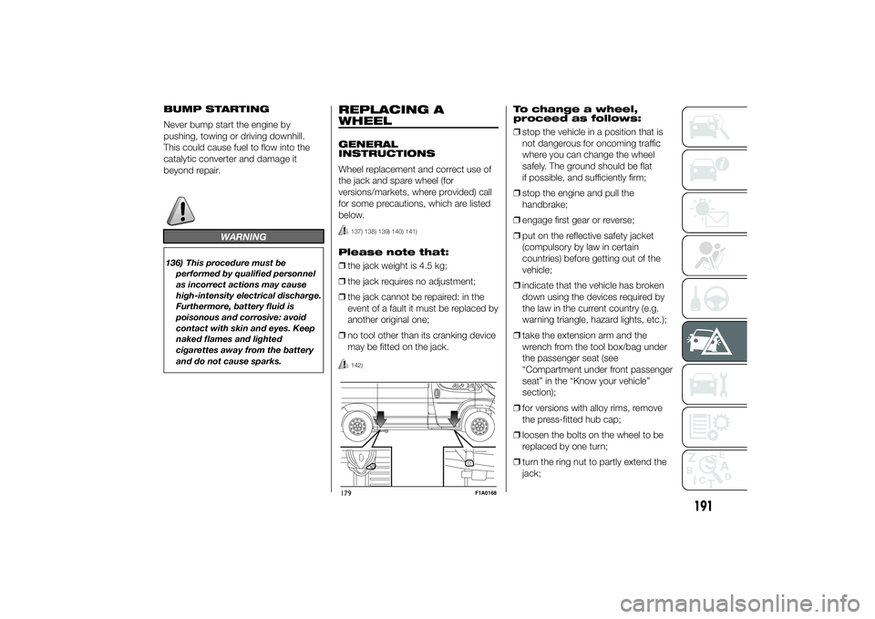
142)
To change a wheel,
proceed as follows:
❒stop the vehicle in a position that is
not dangerous for oncoming traffic
where you can change the wheel
safely. The ground should be flat
if possible, and sufficiently firm;
❒stop the engine and pull the
handbrake;
❒engage first gear or reverse;
❒put on the reflective safety jacket
(compulsory by law in certain
countries) before getting out of the
vehicle;
❒indicate that the vehicle has broken
down using the devices required by
the law in the current country (e.g.
warning triangle, hazard lights, etc.);
❒take the extension arm and the
wrench from the tool box/bag under
the passenger seat (see
“Compartment under front passenger
seat” in the “Know your vehicle”
section);
❒for versions with alloy rims, remove
the press-fitted hub cap;
❒loosen the bolts on the wheel to be
replaced by one turn;
❒turn the ring nut to partly extend the
jack;
179
F1A0168
191
Page 198 of 367
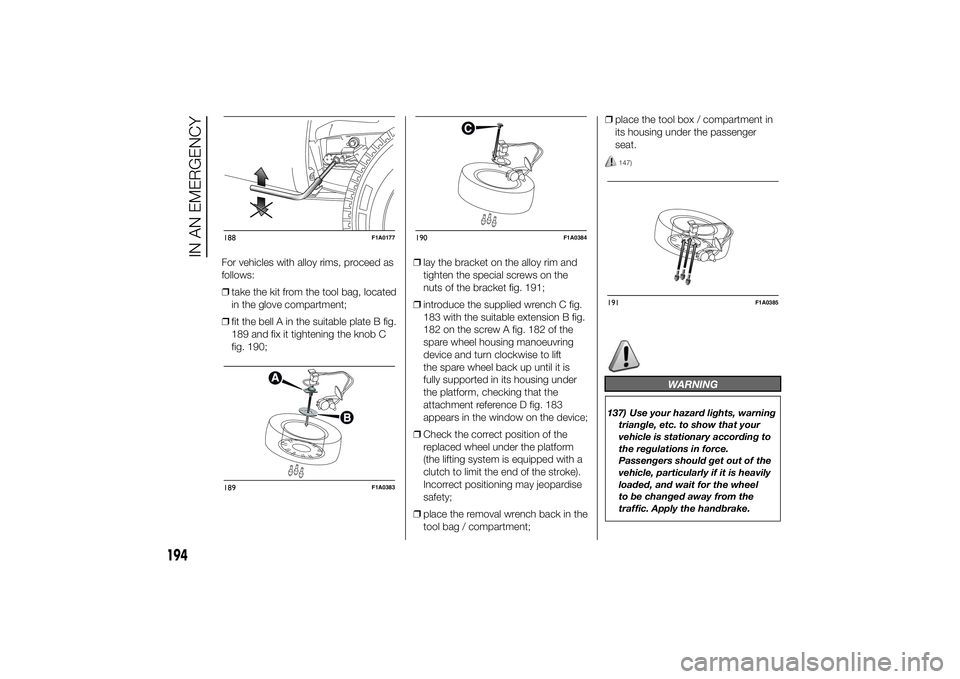
For vehicles with alloy rims, proceed as
follows:
❒take the kit from the tool bag, located
in the glove compartment;
❒fit the bell A in the suitable plate B fig.
189 and fix it tightening the knob C
fig. 190;❒lay the bracket on the alloy rim and
tighten the special screws on the
nuts of the bracket fig. 191;
❒introduce the supplied wrench C fig.
183 with the suitable extension B fig.
182 on the screw A fig. 182 of the
spare wheel housing manoeuvring
device and turn clockwise to lift
the spare wheel back up until it is
fully supported in its housing under
the platform, checking that the
attachment reference D fig. 183
appears in the window on the device;
❒Check the correct position of the
replaced wheel under the platform
(the lifting system is equipped with a
clutch to limit the end of the stroke).
Incorrect positioning may jeopardise
safety;
❒place the removal wrench back in the
tool bag / compartment;❒place the tool box / compartment in
its housing under the passenger
seat.
147)
WARNING
137) Use your hazard lights, warning
triangle, etc. to show that your
vehicle is stationary according to
the regulations in force.
Passengers should get out of the
vehicle, particularly if it is heavily
loaded, and wait for the wheel
to be changed away from the
traffic. Apply the handbrake.
188
F1A0177
189
F1A0383
190
F1A0384
191
F1A0385
194
IN AN EMERGENCY
Page 205 of 367
CHANGING A BULBGENERAL
INSTRUCTIONS
44)158) 159)
❒When a light is not working, check
that the corresponding fuse is intact
before changing a bulb. For the
location of fuses, refer to the
paragraph "Replacing fuses" in this
chapter.
❒before changing a bulb check the
contacts for oxidation;
❒burnt bulbs must be replaced by
others of the same type and power;
❒always check the headlight beam
direction after changing a bulb;
IMPORTANT A slight misting may
appear on the internal surface of the
headlight: this does not indicate a fault
and is caused by low temperature
and the degree of humidity in the air.
Misting will rapidly disappear when the
headlights are switched on. The
presence of drops inside the headlights
indicates infiltration of water. Contact
a Fiat Dealership.
IMPORTANT
44) Halogen bulbs must be handled
by holding the metallic part only.
Touching the transparent part
of the bulb with your fingers may
reduce the intensity of the
emitted light and even reduce the
lifespan of the bulb. In the event
of accidental contact, wipe the
bulb with a cloth moistened with
alcohol and let the bulb dry.
WARNING
158) Modifications or repairs to the
electric system that are not
carried out properly or do not take
the system technical
specifications into account can
cause malfunctions leading to the
risk of fire.
159) Halogen bulbs contain
pressurised gas; in the case of
breakage they may burst.
201
Page 207 of 367
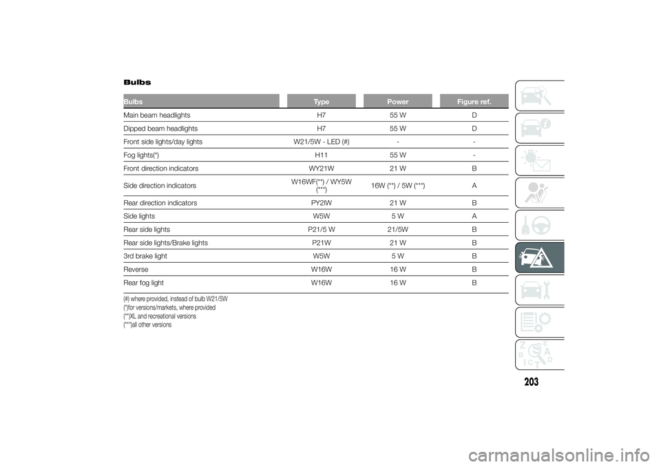
BulbsBulbs Type Power Figure ref.Main beam headlights H7 55 W D
Dipped beam headlights H7 55 W D
Front side lights/day lights W21/5W - LED (#) - -
Fog lights(*) H11 55 W -
Front direction indicators WY21W 21 W B
Side direction indicatorsW16WF(**) / WY5W
(***)16W (**) / 5W (***) A
Rear direction indicators PY2IW 21 W B
Side lights W5W 5 W A
Rear side lights P21/5 W 21/5W B
Rear side lights/Brake lights P21W 21 W B
3rd brake light W5W 5 W B
Reverse W16W 16 W B
Rear fog light W16W 16 W B(#) where provided, instead of bulb W21/5W
(*)for versions/markets, where provided
(**)XL and recreational versions
(***)all other versions
203
Page 209 of 367
REPLACING AN
EXTERIOR BULBFor the type of bulb and power rating,
see “Replacing a bulb”.
FRONT LIGHT CLUSTERS
The front light clusters contain the side
lights and DRLs (where the LED
solution is not provided), dipped beam,
main beam and direction indicator
bulbs.
Bulbs must be replaced with the
headlight removed and placed on a
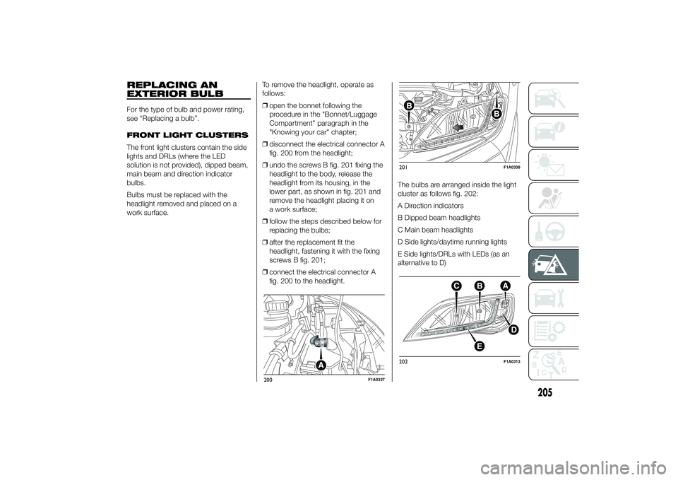
work surface.To remove the headlight, operate as
follows:
❒open the bonnet following the
procedure in the "Bonnet/Luggage
Compartment" paragraph in the
"Knowing your car" chapter;
❒disconnect the electrical connector A
fig. 200 from the headlight;
❒undo the screws B fig. 201 fixing the
headlight to the body, release the
headlight from its housing, in the
lower part, as shown in fig. 201 and
remove the headlight placing it on
a work surface;
❒follow the steps described below for
replacing the bulbs;
❒after the replacement fit the
headlight, fastening it with the fixing
screws B fig. 201;
❒connect the electrical connector A
fig. 200 to the headlight.The bulbs are arranged inside the light
cluster as follows fig. 202:
A Direction indicators
B Dipped beam headlights
C Main beam headlights
D Side lights/daytime running lights
E Side lights/DRLs with LEDs (as an
alternative to D)
200
F1A0337
201
F1A0338
202
F1A0313
205