suspension FIAT DUCATO 2014 Owner handbook (in English)
[x] Cancel search | Manufacturer: FIAT, Model Year: 2014, Model line: DUCATO, Model: FIAT DUCATO 2014Pages: 367, PDF Size: 20.39 MB
Page 2 of 367
We really know your vehicle because we invented,
designed and built it: we really know every single detail. At Fiat Professional Service authorised workshops
you can find technicians directly trained by us, offering quality and professionalism for all service operations.
Fiat Professional workshops are always close to you for the regular servicing operations,
season checks and practical recommendations by our experts.
With Fiat Professional Genuine Parts you keep the reliability, comfort and performance
features of your new vehicle unchanged in time: that's why you bought it for.
Always ask for Genuine Parts for the components used on our vehicles; we recommend them because they come from
our steady commitment in research and development of highly innovative technologies.
For all these reasons:
rely on Genuine Parts, because they are the only ones designed by Fiat Professional for your vehicle.
SAFETY:
BRAKING SYSTEMENVIRONMENT: PARTICULATE FILTERS,
CLIMATE CONTROL SYSTEM MAINTENANCECOMFORT:
SUSPENSION AND WINDSCREEN WIPERSPERFORMANCE:
SPARK PLUGS, INJECTORS
AND BATTERIESLINEACCESSORI:
ROOF RACK BARS, WHEEL RIMS
WHY CHOOSING
GENUINE PARTS
Page 13 of 367
KNOW YOUR VEHICLE
In-depth knowledge of your new vehicle
starts here.
The booklet that you are reading simply
and directly explains how it is made
and how it works.
That’s why we advise you to read it
seated comfortably on board, so that
you can see what is described here for
yourself.SYMBOLS ...................................... 10
THE FIAT CODE SYSTEM ............... 10
THE KEYS....................................... 11
ELECTRONIC ALARM..................... 13
IGNITION SWITCH .......................... 14
SEATS ............................................ 15
HEAD RESTRAINTS ........................ 23
STEERING WHEEL ......................... 24
REAR VIEW MIRRORS .................... 24
HEATING AND VENTILATION.......... 27
DIFFUSERS..................................... 28
HEATING AND VENTILATION
CONTROLS .................................... 28
MANUAL CLIMATE CONTROL
SYSTEM ......................................... 30
AUTOMATIC CLIMATE CONTROL
SYSTEM ......................................... 33
ADDITIONAL HEATER ..................... 38
INDEPENDENT ADDITIONAL
HEATER .......................................... 39
EXTERNAL LIGHTS......................... 44
WINDOW CLEANING ...................... 48
CRUISE CONTROL ......................... 50
ROOF LIGHTS ................................ 53
CONTROLS .................................... 54
FUEL CUT-OFF SWITCH ................ 57
INTERIOR FITTINGS ...................... 58
TACHOGRAPH ............................... 63SPEED BLOCK ............................... 64
SELF-LEVELLING AIR
SUSPENSION ................................. 64
DOORS ........................................... 65
ELECTRIC WINDOWS .................... 70
BONNET ......................................... 71
ROOF RACK/SKI RACK .................. 72
HEADLIGHTS.................................. 73
ABS ................................................ 74
ESC (ELECTRONIC STABILITY
CONTROL) SYSTEM ....................... 75
TRACTION PLUS SYSTEM ............. 79
TPMS (TYRE PRESSURE
MONITORING SYSTEM) ................. 80
DRIVING ADVISOR ......................... 83
REAR CAMERA (PARKVIEW®
REAR BACK UP CAMERA) ............. 89
TRAFFIC SIGN RECOGNITION ....... 90
EOBD SYSTEM............................... 92
PARKING SENSORS....................... 93
START&STOP SYSTEM .................. 95
RADIO............................................. 98
ACCESSORIES PURCHASED BY
THE OWNER................................... 99
REFUELLING THE VEHICLE ...........100
PROTECTING THE
ENVIRONMENT ..............................101
9
Page 68 of 367
SPEED BLOCK(for versions/markets, where provided)
The vehicle is equipped with a speed
limitation function that can be set at the
user's request to one of 4 predefined
values: 90, 100, 110, 130 km/h.
To activate/deactivate this function,
contact a Fiat Dealership.
Following the operation, a sticker will be
applied to the windscreen showing the
maximum speed setting.
IMPORTANT The speedometer could
indicate a higher maximum speed than
the effective one, set by the Dealership,
in accordance with the regulations in
force.
SELF-LEVELLING AIR
SUSPENSIONGENERAL INFORMATION
The system only acts on the rear
wheels.
The system maintains the rear ride
setting for the vehicle constant in any
loading condition, while ensuring a
greater driving comfort. In addition, the
system allows the height of the vehicle
to be adjusted with the vehicle
stationary, by selecting from 7 different
positions to facilitate access to the
rear compartment.
HEIGHT ADJUSTMENT
There are 7 pre-defined levels for the
free height from the ground: from “ride
-3” to “ride 0” till “ride +3”.
The multifunction display, located in the
middle of the instrument panel, can
show the ride position.
Automatic adjustment
When moving, the system automatically
shows that the vehicle is in 'ride setting
0' and keeps it constant.
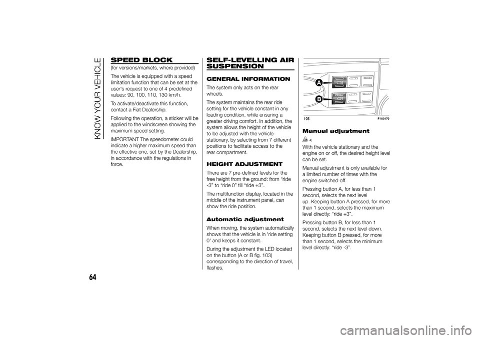
During the adjustment the LED located
on the button (A or B fig. 103)
corresponding to the direction of travel,
flashes.Manual adjustment
4)
With the vehicle stationary and the
engine on or off, the desired height level
can be set.
Manual adjustment is only available for
a limited number of times with the
engine switched off.
Pressing button A, for less than 1
second, selects the next level
up. Keeping button A pressed, for more
than 1 second, selects the maximum
level directly: “ride +3”.
Pressing button B, for less than 1
second, selects the next level down.
Keeping button B pressed, for more
than 1 second, selects the minimum
level directly: “ride -3”.103
F1A0170
64
KNOW YOUR VEHICLE
Page 95 of 367
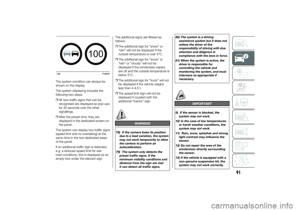
The system condition can always be
shown on the display.
The system displaying includes the
following two steps:
❒All new traffic signs that can be
recognised are displayed as pop-ups
for 40 seconds over the other
signallings.
❒After the preset time, they are
displayed in the dedicated screen on
the panel.
The system can display two traffic signs
(speed limit and no overtaking) at the
same time in the two dedicated areas
of the panel.
If an additional traffic sign is detected,
e.g. a reduced speed limit for wet
road conditions, this is displayed as an
empty box under the relevant sign.The additional signs are filtered as
follows:
❒The additional sign for "snow" or
"rain" will not be displayed if the
outside temperature is over 3°C.
❒The additional sign for "snow" or
"rain" or "cloudy" will not be
displayed if the windscreen wipers
are off and the outside temperature is
below 3°C.
❒The additional sign for "truck" will not
be displayed if the vehicle weighs
less than 4-4.5 t.
❒The speed limit sign will not be
displayed if coupled with the
additional "tractor" sign.
WARNING
78) If the camera loses its position
due to a load variation, the system
may not work temporarily to allow
the camera to perform an
autocalibration.
79) The system only detects the
preset traffic signs. If the
minimum visibility conditions and
distance from the sign are met
it can detect all traffic signs.80) The system is a driving
assistance system but it does not
relieve the driver of the
responsibility of driving with due
attention and diligence in
compliance with the laws in force.
81) When the system is active, the
driver is responsible for
controlling the vehicle and
monitoring the system, and must
intervene as appropriate if
necessary.
IMPORTANT
9) If the sensor is blocked, the
system may not work.
10) In the case of low temperatures
or harsh weather conditions, the
system may not work.
11) Rain, snow, splashes and strong
light contrast may influence the
sensor.
12) Do not repair the area of the
windscreen directly surrounding
the sensor.
13) If the vehicle is equipped with a
non-genuine suspension kit, the
system may not work correctly.
100
130
F1A0373
91
Page 98 of 367
❒Objects close to the vehicle, in
certain circumstances are not
detected and could therefore cause
damage to the vehicle or be
damaged.
The following conditions may influence
the performance of the parking
assistance system:
❒Reduced sensor sensitivity and a
reduction in the parking assistance
system performance could be due to
the presence on the surface of the
sensor of: ice, snow, mud, thick
paint.
❒The sensor may detect a non-
existent obstacle (echo noise) due to
mechanical noises, for example
when washing the vehicle, in case of
rain, strong wind, hail.
❒The signals sent by the sensors can
also be altered by the presence of
ultrasonic systems (e.g. pneumatic
brake systems or pneumatic drills)
near the vehicle.❒The performance of the parking
assistance system may also be
affected by the position of the
sensors. For example by a change in
the ride setting (caused by the wear
of the shock absorbers, suspension),
changing the tyres, overloading the
vehicle and carrying out specific
tuning operations that require the
vehicle to be lowered.
❒Detection of obstacles in the upper
part of the vehicle (particularly in the
case of vans or chassis cabs) may
not be guaranteed because the
system detects obstacles that could
strike the lower part of the vehicle.
IMPORTANT
16) The sensor must be clean of
mud, dirt, snow or ice in order for
the system to operate correctly.
Be careful not to scratch or
damage the sensors while
cleaning them. Avoid using dry,
rough or hard cloths. The sensors
must be washed using clean
water, with the addition of car
shampoo if necessary.
WARNING
82) The responsibility for parking
and other dangerous manoeuvres
always and in every case lies
with the driver. While carrying out
these manoeuvres, always make
sure that no people (especially
children) or animals are in the
area concerned. The parking
sensors are used to assist the
driver, who must never allow his
attention to lapse during
potentially dangerous
manoeuvres, even those executed
at low speeds.
94
KNOW YOUR VEHICLE
Page 107 of 367
KNOWING THE INSTRUMENT PANEL
This section of the booklet gives you all
the information you need to
understand, interpret and use the
instrument panel correctly.CONTROL PANEL AND
INSTRUMENTS ...............................104
DISPLAY ........................................109
TRIP COMPUTER ...........................118
WARNING LIGHTS AND
MESSAGES ....................................121
- LOW BRAKE FLUID/HANDBRAKE
ENGAGED .......................................... 121
- EBD FAILURE .................................. 122
- AIRBAG FAILURE ............................. 122
- SEAT BELTS NOT FASTENED .......... 123
- ENGINE COOLANT TEMPERATURE
TOO HIGH .......................................... 124
- LOW BATTERY CHARGE ................. 124
- LOW ENGINE OIL PRESSURE ......... 125
-ENGINE OIL DETERIORATED ........... 125
-INCOMPLETE DOOR/LOAD
COMPARTMENT CLOSURE ............... 126
- POWER STEERING FAILURE ........... 126
-SELF-LEVELLING SUSPENSION
FAILURE ............................................. 126
- INJECTION/EOBD SYSTEM
FAILURE ............................................. 128
- ABS FAILURE ................................... 129
-FUEL RESERVE ................................ 129
- GLOW PLUG HEATING/GLOW
PLUG HEATING FAILURE ................... 130
- WATER IN DIESEL FILTER ................ 130
-VEHICLE PROTECTION SYSTEM
FAILURE - FIAT CODE ........................ 131
- REAR FOG LIGHTS .......................... 131
-GENERIC FAILURE INDICATION ....... 131
-DPF (PARTICULATE FILTER)
CLEANING UNDERWAY ..................... 133
-WORN BRAKE PADS ........................ 134
-DRIVING ADVISOR ........................... 135
- TPMS ............................................... 136
- DIPPED HEADLIGHTS ..................... 137- FOLLOW ME HOME ........................ 137
- LEFT-HAND DIRECTION INDICATOR
............................................................ 137
- RIGHT-HAND DIRECTION
INDICATOR ........................................ 138
-FOG LIGHTS ..................................... 138
- CRUISE CONTROL .......................... 138
-SPEED LIMITER ................................ 138
- AUTOMATIC MAIN BEAM
HEADLIGHTS ..................................... 139
- MAIN BEAM HEADLIGHTS .............. 139
-EXTERIOR LIGHTS FAULT ................ 140
-BRAKE LIGHT FAILURE .................... 140
-MAIN BEAM AUTOMATISM FAULT ... 141
-POSSIBLE ICE ON ROAD ................. 141
-SPEED LIMIT EXCEEDED ................. 141
-SCHEDULED SERVICING ................. 141
-DRIVING ADVISOR SYSTEM
FAILURE ............................................. 142
-TRAFFIC SIGN RECOGNITION
FAILURE ............................................. 142
-LIMITED RANGE ............................... 142
-START&STOP SYSTEM
ACTIVATION/DEACTIVATION .............. 143
-START&STOP FAILURE .................... 143
103
Page 130 of 367
Warning lights on
displayWhat it means What to do
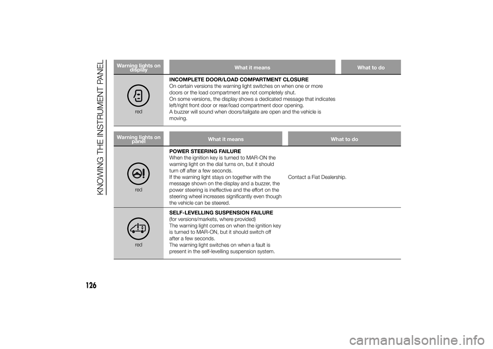
redINCOMPLETE DOOR/LOAD COMPARTMENT CLOSURE
On certain versions the warning light switches on when one or more
doors or the load compartment are not completely shut.
On some versions, the display shows a dedicated message that indicates
left/right front door or rear/load compartment door opening.
A buzzer will sound when doors/tailgate are open and the vehicle is
moving.
Warning lights on
panelWhat it means What to do
redPOWER STEERING FAILURE
When the ignition key is turned to MAR-ON the
warning light on the dial turns on, but it should
turn off after a few seconds.
If the warning light stays on together with the
message shown on the display and a buzzer, the
power steering is ineffective and the effort on the
steering wheel increases significantly even though
the vehicle can be steered.Contact a Fiat Dealership.redSELF-LEVELLING SUSPENSION FAILURE
(for versions/markets, where provided)
The warning light comes on when the ignition key
is turned to MAR-ON, but it should switch off
after a few seconds.
The warning light switches on when a fault is
present in the self-levelling suspension system.
126
KNOWING THE INSTRUMENT PANEL
Page 177 of 367
WARNING
126) Never leave children
unattended in the vehicle. Always
remove the ignition key when
leaving the vehicle and take it out
with you.
IMPORTANT
33) If the vehicle is equipped with
self-levelling air suspension,
always check that there is
sufficient space above the roof
and around the vehicle when
parking. Indeed, the vehicle could
raise (or lower) automatically
depending on load or temperature
changes.
USING THE
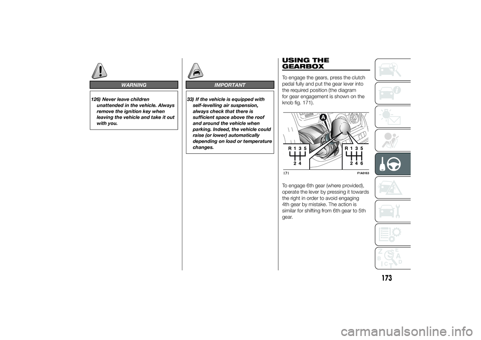
GEARBOXTo engage the gears, press the clutch
pedal fully and put the gear lever into
the required position (the diagram
for gear engagement is shown on the
knob fig. 171).
To engage 6th gear (where provided),
operate the lever by pressing it towards
the right in order to avoid engaging
4th gear by mistake. The action is
similar for shifting from 6th gear to 5th
gear.171
F1A0163
173
Page 196 of 367
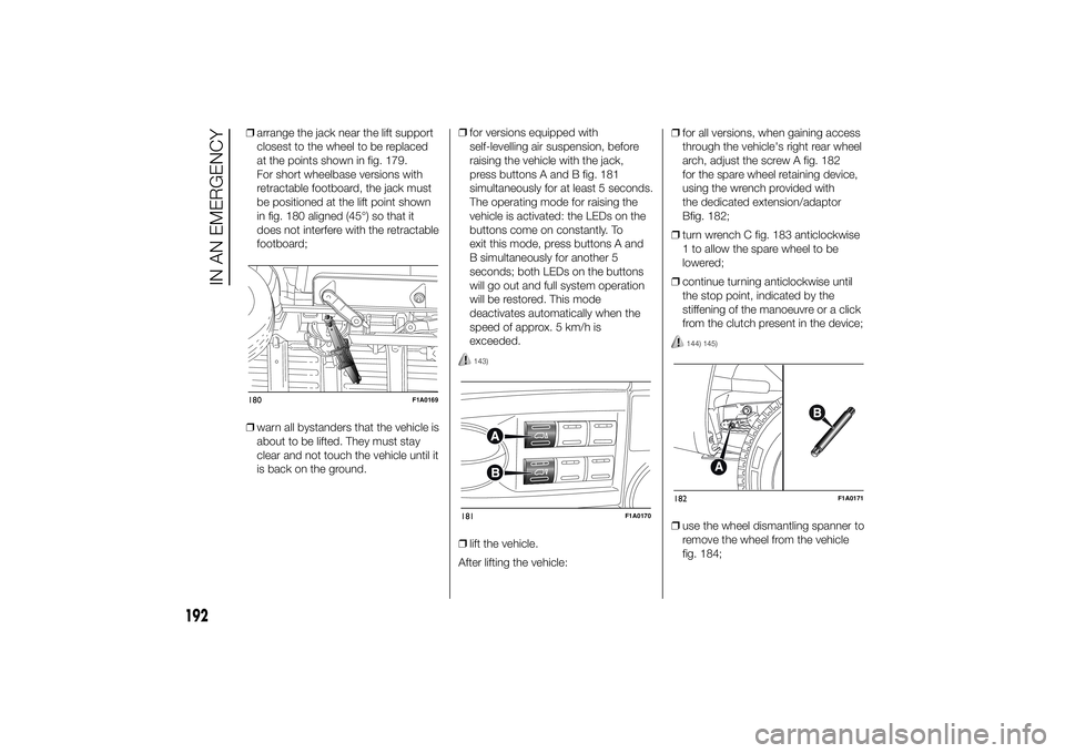
❒arrange the jack near the lift support
closest to the wheel to be replaced
at the points shown in fig. 179.
For short wheelbase versions with
retractable footboard, the jack must
be positioned at the lift point shown
in fig. 180 aligned (45°) so that it
does not interfere with the retractable
footboard;
❒warn all bystanders that the vehicle is
about to be lifted. They must stay
clear and not touch the vehicle until it
is back on the ground.❒for versions equipped with
self-levelling air suspension, before
raising the vehicle with the jack,
press buttons A and B fig. 181
simultaneously for at least 5 seconds.
The operating mode for raising the
vehicle is activated: the LEDs on the
buttons come on constantly. To
exit this mode, press buttons A and
B simultaneously for another 5
seconds; both LEDs on the buttons
will go out and full system operation
will be restored. This mode
deactivates automatically when the
speed of approx. 5 km/h is
exceeded.
143)
❒lift the vehicle.
After lifting the vehicle:❒for all versions, when gaining access
through the vehicle's right rear wheel
arch, adjust the screw A fig. 182
for the spare wheel retaining device,
using the wrench provided with
the dedicated extension/adaptor
Bfig. 182;
❒turn wrench C fig. 183 anticlockwise
1 to allow the spare wheel to be
lowered;
❒continue turning anticlockwise until
the stop point, indicated by the
stiffening of the manoeuvre or a click
from the clutch present in the device;
144) 145)
❒use the wheel dismantling spanner to
remove the wheel from the vehicle
fig. 184;
180
F1A0169
181
F1A0170
182
F1A0171
192
IN AN EMERGENCY
Page 199 of 367
138) The spare wheel supplied (for
versions/markets, where
provided) is specific for your
vehicle. Therefore, it must not be
used on other models. Do not
use spare wheels of other models
on your vehicle. The wheel bolts
are specific for your vehicle: do
not use them on different models
and do not use bolts from other
models on your car.
139) Have the wheel repaired and
refitted as soon as possible. Do
not apply grease to the bolt
threads before fitting: they could
come unscrewed.
140) Use the jack only to replace
wheels on the vehicle with which
it is supplied or on other vehicles
of the same model. Never use
the jack for other purposes, such
as lifting other car models. Never
use the jack to carry out repairs
under the vehicle. Incorrect
positioning of the jack may cause
the lifted vehicle to fall. Do not
use the jack for loads higher than
those shown on the label.
141) Never tamper with the inflation
valve. Never introduce tools of any
kind between rim and tyre. Check
tyre and spare wheel pressure
regularly, referring to the values
shown in the "Technical
specifications" section.142) No tools other than the crank
provided should be used with
the spare wheel lifting device; it
should be operated by hand only.
143) On versions equipped with
self-levelling air suspension, never
introduce the head or hands in
the wheel arch: the vehicle could
raise or lower automatically
depending on possible load or
temperature changes.
144) The device should only be
operated by hand, without using
any type of tool other than the
crank provided, like pneumatic or
electrical screwers.
145) The moving components of the
jack (screw and joints) can also
cause injuries: do not touch them.
If you come into contact with
lubricating grease, clean yourself
thoroughly.146) At the end of the operation of
raising/locking the spare wheel,
after having checked the correct
positioning of the wheel under the
platform (white notch inside the
window on the device), the key
must be extracted, taking care not
to turn it in the wrong direction
to facilitate the extraction of the
key itself, to prevent the
attachment device from being
released and the wheel assembly
not being securely retained fig.
188.
147) Each time the spare wheel is
moved, check that it is correctly
positioned in its housing under
the platform. If it is not correctly
positioned, this could adversely
affect safety.
195