High pressure FIAT DUCATO 2016 3.G Owners Manual
[x] Cancel search | Manufacturer: FIAT, Model Year: 2016, Model line: DUCATO, Model: FIAT DUCATO 2016 3.GPages: 296, PDF Size: 15.08 MB
Page 49 of 296
KNOWING THE INSTRUMENT PANEL
This section of the booklet gives you all
the information you need to
understand, interpret and use the
instrument panel correctly.EOBD SYSTEM............................... 49
CONTROL PANEL AND
ON-BOARD INSTRUMENTS ........... 50
DISPLAY ........................................ 52
TRIP COMPUTER ........................... 54
WARNING LIGHTS AND
MESSAGES .................................... 56
- LOW BRAKE FLUID/HANDBRAKE
APPLIED ............................................ 56
- EBD FAILURE .................................. 57
- AIR BAG FAILURE ............................ 57
- SEAT BELTS REMINDER .................. 57
- ENGINE COOLANT TEMPERATURE
TOO HIGH .......................................... 58
- LOW BATTERY CHARGE ................. 59
- LOW ENGINE OIL PRESSURE ......... 60
-ENGINE OIL DETERIORATED ........... 60
-INCOMPLETE DOOR/LOAD
COMPARTMENT CLOSURE ............... 61
-POWER STEERING FAILURE ............ 61
- SELF-LEVELLING SUSPENSION
FAILURE ............................................. 61
- EOBD/INJECTION SYSTEM
FAILURE ............................................. 63
-UREA INJECTION SYSTEM FAILURE
............................................................ 64
-ABS FAILURE .................................... 64
- FUEL RESERVE ............................... 64
-GLOW PLUG PREHEATING / GLOW
PLUG PREHEATING FAILURE ............ 65
-LOW DIESEL EMISSIONS ADDITIVE
(UREA) LEVEL WARNING ................... 65
-VEHICLE PROTECTION SYSTEM
FAILURE - FIAT CODE ........................ 66
-REAR FOG LIGHTS ........................... 66
- GENERAL FAILURE WARNING ........ 67-DPF (PARTICULATE FILTER)
CLEANING UNDERWAY ..................... 68
- BRAKE PAD WEAR .......................... 68
-DRIVING ADVISOR ........................... 69
- TPMS ............................................... 70
-DIPPED BEAM HEADLIGHTS ........... 71
-FOLLOW ME HOME ......................... 71
- LEFT DIRECTION INDICATOR .......... 71
- RIGHT DIRECTION INDICATOR ....... 71
- FOG LIGHTS .................................... 72
- CRUISE CONTROL .......................... 72
- SPEED LIMITER ............................... 72
- AUTOMATIC MAIN BEAM
HEADLIGHTS ..................................... 72
- MAIN BEAM HEADLIGHTS .............. 72
-"UP" FUNCTION ............................... 73
-EXTERIOR LIGHTS FAILURE ............. 74
-LOW ENGINE OIL PRESSURE
WARNING LIGHT FAILURE ................. 74
-BRAKE LIGHTS FAILURE .................. 74
-MAIN BEAM AUTOMATISM FAULT ... 74
-POSSIBLE ICE ON ROAD ................. 75
-SPEED LIMIT EXCEEDED ................. 75
-SCHEDULED SERVICING ................. 75
-FUEL CUT-OFF DEVICE INERTIA
SWITCH TRIPPED .............................. 76
-COMFORT-MATIC SYSTEM FAILURE
INDICATION ........................................ 76
-PARKING SENSOR FAILURE ............ 76
-DRIVING ADVISOR SYSTEM
FAILURE ............................................. 76
-TRAFFIC SIGN RECOGNITION
FAILURE ............................................. 76
-LIMITED RANGE ............................... 76
-START&STOP SYSTEM
ACTIVATION/DEACTIVATION .............. 77
-START&STOP FAILURE .................... 77
47
Page 84 of 296
ESC (Electronic
Stability Control)
SYSTEM
(for versions/markets, where provided)
The ESC system improves the
directional control and stability of the
vehicle in various driving conditions.
The ESC system corrects the vehicle’s
understeer and oversteer, distributing
the brake force on the appropriate
wheels. The torque supplied by the
engine can also be reduced in order to
maintain control of the vehicle.
The ESC system uses the sensors in
the vehicle to determine the trajectory
required by the driver through steering
and compares it with the real trajectory
of the vehicle. When the real trajectory
deviates from the desired trajectory, the
ESC system intervenes to counter the
car’s understeer or oversteer.
Oversteer: occurs when the vehicle
is turning more than it should according
to the angle of the steering wheel.
Understeer: occurs when the vehicle
is turning less than it should according
to the angle of the steering wheel.The ESC system also includes the
following subsystems:
Hill Holder
ASR
HBA
ERM
HDC
57) 58) 59)
SYSTEM INTERVENTION
This is signalled by the flashing of the
warning light in the instrument panel,
to inform the driver that the vehicle is
in critical stability and grip conditions.
SYSTEM ACTIVATION
The ESC system switches on
automatically when the engine is
started and cannot be switched off.
HILL HOLDER SYSTEM
This system is an integral part of the
ESC system and facilitates starting on
slopes.
It is automatically activated in the
following conditions:
uphill: vehicle stationary on a road
with a gradient higher than 5%, engine
running, brake pressed and gearbox
in neutral or gear (other than reverse)
engaged;
downhill: vehicle stationary on a road
with a gradient higher than 5%, engine
running, brake pressed and reverse
gear engaged.
When setting off, the ESC system
control unit maintains the braking
pressure on the wheels until the torque
necessary for starting is reached, or
in any case for a maximum of 2
seconds, allowing your right foot to be
moved easily from the brake pedal to
the accelerator.
When two seconds have elapsed,
without starting, the system is
automatically deactivated, gradually
releasing the braking pressure. During
this release stage, the typical brake
disengagement noise indicating that the
vehicle is going to move imminently
will be heard.
IMPORTANT The Hill Holder system is
not a parking brake; therefore, never
leave the vehicle without having
engaged the handbrake, turned the
engine off and engaged first gear,
so that it is parked in safe conditions
(for further information read the
"Parking" paragraph in the "Starting
and driving" chapter).
82
SAFETY
Page 85 of 296
ASR (AntiSlip
Regulation) SYSTEM
It is an integral part of the ESC system.
It automatically operates in the event
of one or both drive wheels slipping,
loss of grip on wet roads (aquaplaning)
and acceleration on slippery, snowy
or icy roads, etc.
Depending on the slipping conditions,
two different control systems are
activated:
if the slipping involves both drive
wheels, the ASR intervenes reducing
the power transmitted by the engine;
if the slipping only involves one
of the drive wheels, it intervenes
automatically braking the wheel that is
slipping.
60)
Engagement/ disengagement of the
ASR system
The ASR is switched on automatically
each time the engine is started.
While driving, the ASR can be switched
off and subsequently switched on
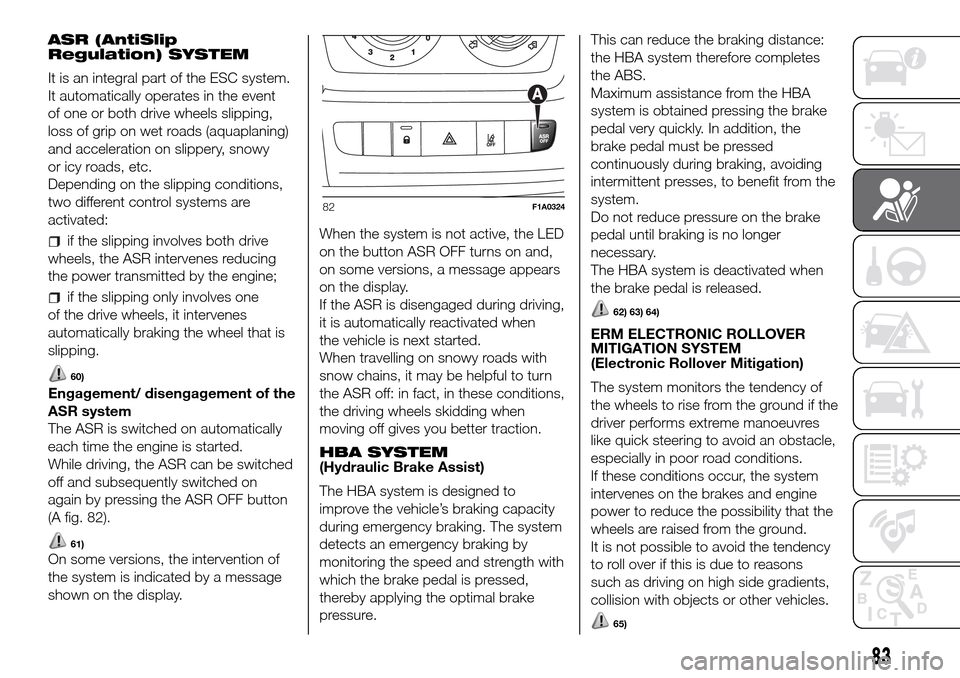
again by pressing the ASR OFF button
(A fig. 82).
61)
On some versions, the intervention of
the system is indicated by a message
shown on the display.When the system is not active, the LED
on the button ASR OFF turns on and,
on some versions, a message appears
on the display.
If the ASR is disengaged during driving,
it is automatically reactivated when
the vehicle is next started.
When travelling on snowy roads with
snow chains, it may be helpful to turn
the ASR off: in fact, in these conditions,
the driving wheels skidding when
moving off gives you better traction.
HBA SYSTEM
(Hydraulic Brake Assist)
The HBA system is designed to
improve the vehicle’s braking capacity
during emergency braking. The system
detects an emergency braking by
monitoring the speed and strength with
which the brake pedal is pressed,
thereby applying the optimal brake
pressure.This can reduce the braking distance:
the HBA system therefore completes
the ABS.
Maximum assistance from the HBA
system is obtained pressing the brake
pedal very quickly. In addition, the
brake pedal must be pressed
continuously during braking, avoiding
intermittent presses, to benefit from the
system.
Do not reduce pressure on the brake
pedal until braking is no longer
necessary.
The HBA system is deactivated when
the brake pedal is released.
62) 63) 64)
ERM ELECTRONIC ROLLOVER
MITIGATION SYSTEM
(Electronic Rollover Mitigation)
The system monitors the tendency of
the wheels to rise from the ground if the
driver performs extreme manoeuvres
like quick steering to avoid an obstacle,
especially in poor road conditions.
If these conditions occur, the system
intervenes on the brakes and engine
power to reduce the possibility that the
wheels are raised from the ground.
It is not possible to avoid the tendency
to roll over if this is due to reasons
such as driving on high side gradients,
collision with objects or other vehicles.
65)
82F1A0324
83
Page 88 of 296
WARNING
66)The Traction Plus system acts
effectively only on road surfaces that are
not homogeneous and/or differentiated
between the two drive wheels.
67)Until the setting off manoeuvre is
terminated, fully depress the accelerator
pedal in order to transfer all the drive
torque to the wheel with the best grip.
TPMS (Tyre
Pressure
Monitoring System)
(for versions/markets, where provided)
68) 69) 70) 71) 72) 73) 74) 75) 76)
DESCRIPTION
The tyre pressure monitoring system
(TPMS) warns the driver of low tyre
pressure on the basis of the cold
inflation pressure prescribed for the
vehicle.
Changes in outside temperature may
cause tyre pressure to vary. This means
that a decrease in the outside
temperature corresponds to a decrease
in the tyre pressure.
Tyre pressure must always be adjusted
according to the cold inflation pressure.
Cold tyre inflation pressure is the tyre
pressure after letting the vehicle stand
for at least three hours or a travel
shorter than 1.6 km after an interval of
three hours.
The cold tyre inflation pressure must
not exceed the maximum inflation
pressure value printed on the side of
the tyre.
The tyre pressure also increases while
driving the vehicle: this is a normal
condition and does not require any
adjustment of the pressure.The TPMS continues to advise the
driver of the low tyre pressure condition
until this is corrected; the warning
continues until the pressure
corresponds or exceeds the pressure
prescribed for the cold tyres. When the
low tyre pressure check warning light
turns on continuously, the inflation
pressure must be adjusted until it
reaches the pressure prescribed for
cold tyres. After the automatic update
of the system, the tyre pressure control
warning light switches off. You may
need to drive the vehicle for about 20
minutes at a speed higher than 20
km/h to allow the TPMS to receive this
information.
NOTE
The TPMS does not replace the
normal tyre maintenance service and
does not indicate any fault in a tyre.
Therefore, the TPMS should not be
used as pressure switch while adjusting
the tyre inflation pressure.
Driving with insufficient tyre pressure
causes their overheating and can
result in tyre failure. The low inflation
pressure reduces fuel efficiency and
tyre tread life and may also affect
handling and braking performance of
the vehicle.
86
SAFETY
Page 89 of 296
The TPMS does not replace the
correct tyre maintenance. It is up to the
driver to maintain the correct tyre
pressure level measuring it with
a suitable pressure switch. This is
necessary even if the decrease in the
inflation pressure value does not cause
the tyre pressure control warning light
to switch on.
The TPMS warns the driver of any
condition of insufficient tyre pressure
If this drops below the insufficient
pressure limit for any reason including
low temperature and normal pressure
loss of the tyre.
The seasonal temperature changes
affect tyre pressure.
The TPMS uses wireless devices with
electronic sensors mounted on the
wheel rims to constantly monitor the
value of tyre pressure. The sensors
mounted on each wheel as part of the
valve stem transmit various information
of the tyres to the receiver module, in
order to calculate the pressure.
IMPORTANT Monitoring and
maintaining the correct pressure in all
four tyres are particularly important.Tyre pressure monitoring system
low pressure warnings
The system warns the driver if one or
more tyres are flat by turning on the
warning light on the instrument
panel (together with a warning message
and an acoustic signal).
In this case, stop the vehicle as soon as
possible, check the inflation pressure
of each tyre and inflate to the cold tyre
pressure value prescribed for the
vehicle. The system will automatically
update and after receiving the tyre
pressure update the tyre pressure
control warning light switches off. You
may need to drive the vehicle for about
20 minutes at a speed higher than 20
km/h to allow the system to receive this
information.
TPMS operation faults
The system fault is indicated by the
corresponding warning light
, which
first flashes for 75 seconds and then
stays on continuously. This can occur in
any of the following situations:
interference caused by electronic
devices or radio frequency emissions
similar to those of the TPM sensors.
Application of tinted films which
interfere with the signals of the radio
waves.
Presence of snow or ice on the
wheels or the wheel arches.
Use of snow chains.
Use of wheels/tyres not equipped
with TPM sensors.
The space-saver wheel is not
equipped with the tyre pressure control
sensor. Therefore, the tyre pressure is
not controlled by the system.
If the space-saver wheel replaces a
tyre with a pressure lower than the
insufficient pressure limit, an acoustic
signal will be emitted and the
warning light will turn on at the next
start-up.
When the original tyre is repaired or
replaced and it is mounted back on
the vehicle to replace the space-saver
wheel, the TPMS will update
automatically and the warning light will
switch off, provided that the pressure of
none of the four tyres is below the
insufficient pressure limit. You may need
to drive the vehicle for about 20
minutes at a speed higher than 20
km/h to allow the TPMS to receive this
information.
87
Page 90 of 296
WARNING
68)The TPMS is optimised for the original
tyres and wheels provided. TPMS
pressures and alerts have been defined
according to the size of the tyres mounted
on the vehicle. Using equipment with
different size, type or kind may cause
irregular system operation or sensor
damage. Non-original spare wheels can
damage the sensor. Do not use tyre
sealant or balancing weights if the vehicle
is equipped with TPMS as these may
damage the sensors.
69)If the system signals a pressure
decrease on a specific tyre, it is
recommended to check the pressure on all
four tyres.
70)The TPMS does not relieve the driver
from the obligation to check the tyre
pressure every month; it is not even to be
considered a replacing system for
maintenance or a safety system.
71)Tyre pressure must be checked with
tyres cold. Should it become necessary for
whatever reason to check pressure with
warm tyres, do not reduce pressure even
though it is higher than the prescribed
value, but repeat the check when tyres are
cold.
72)The TPMS cannot indicate sudden tyre
pressure drops (for example when a tyre
bursts). In this case, stop the vehicle,
braking with caution and avoiding abrupt
steering.73)The system only warns that the tyre
pressure is low: it is not able to inflate
them.
74)Insufficient tyre inflation increases fuel
consumption, reduces the tread duration
and may affect your ability to drive the
vehicle safely.
75)Always refit the valve stem cap after
inspecting or adjusting tyre pressure. This
prevents dampness or dirt from entering
the valve stem and thus the pressure
control sensor from being damaged.
76)The tyre repair kit (Fix&Go) provided
with the vehicle (for versions/markets,
where provided) is compatible with the
TPMS sensors; using sealants not
equivalent with that in the original kit may
adversely affect its operation. If sealants
not equivalent with the original one are
used, it is recommended to have the
TPMS sensors checked by a qualified
repair centre.
88
SAFETY
Page 123 of 296
When the device is active, the vehicle
speed depends on the accelerator
pedal, until the programmed speed limit
is reached (see "Speed limit
programming" paragraph).
If necessary (in the event of overtaking
for example), the set speed limit can
be exceeded by fully depressing the
accelerator pedal.
By gradually reducing the pressure on
the accelerator pedal, the function
will be reactivated as soon as the
vehicle speed drops below the
programmed speed.
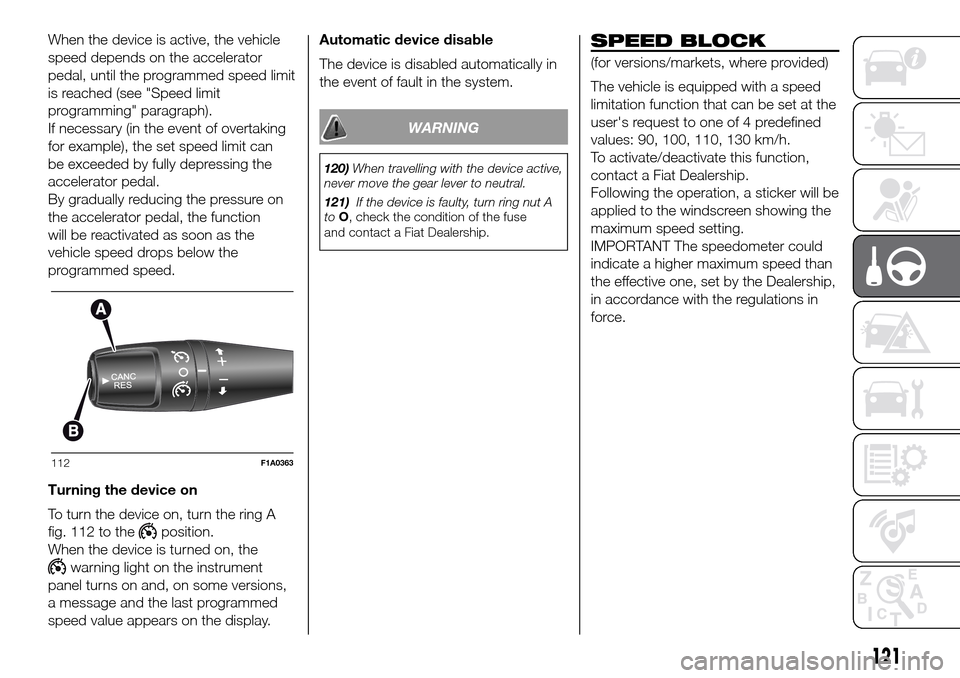
Turning the device on
To turn the device on, turn the ring A
fig. 112 to the
position.
When the device is turned on, the
warning light on the instrument
panel turns on and, on some versions,
a message and the last programmed
speed value appears on the display.Automatic device disable
The device is disabled automatically in
the event of fault in the system.
WARNING
120)When travelling with the device active,
never move the gear lever to neutral.
121)If the device is faulty, turn ring nut A
toO, check the condition of the fuse
and contact a Fiat Dealership.
SPEED BLOCK
(for versions/markets, where provided)
The vehicle is equipped with a speed
limitation function that can be set at the
user's request to one of 4 predefined
values: 90, 100, 110, 130 km/h.
To activate/deactivate this function,
contact a Fiat Dealership.
Following the operation, a sticker will be
applied to the windscreen showing the
maximum speed setting.
IMPORTANT The speedometer could
indicate a higher maximum speed than
the effective one, set by the Dealership,
in accordance with the regulations in
force.
112F1A0363
121
Page 124 of 296
PARKING SENSORS
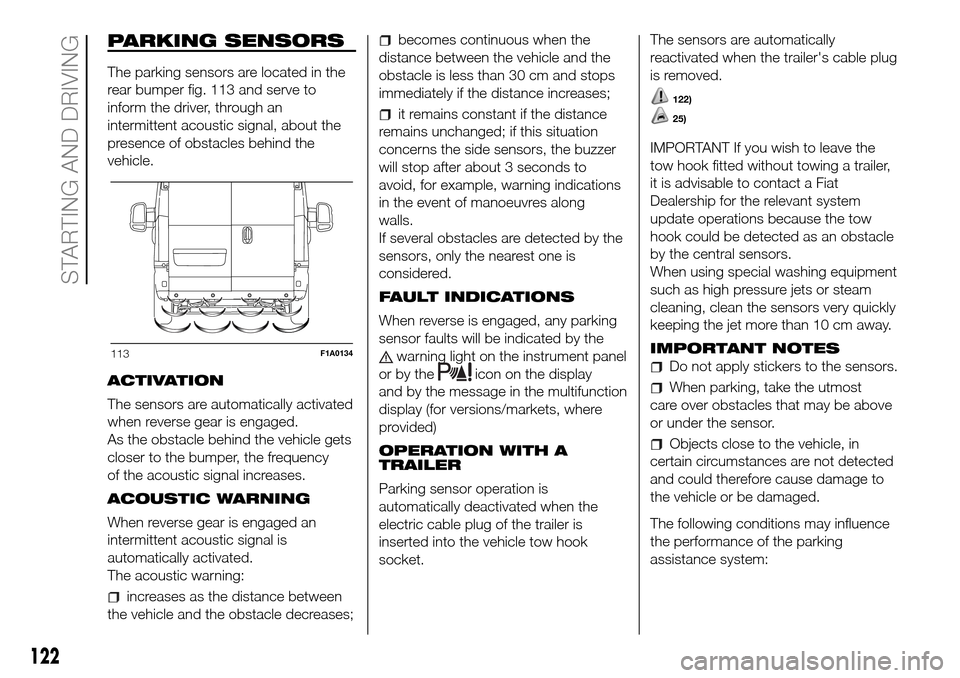
The parking sensors are located in the
rear bumper fig. 113 and serve to
inform the driver, through an
intermittent acoustic signal, about the
presence of obstacles behind the
vehicle.
ACTIVATION
The sensors are automatically activated
when reverse gear is engaged.
As the obstacle behind the vehicle gets
closer to the bumper, the frequency
of the acoustic signal increases.
ACOUSTIC WARNING
When reverse gear is engaged an
intermittent acoustic signal is
automatically activated.
The acoustic warning:
increases as the distance between
the vehicle and the obstacle decreases;
becomes continuous when the
distance between the vehicle and the
obstacle is less than 30 cm and stops
immediately if the distance increases;
it remains constant if the distance
remains unchanged; if this situation
concerns the side sensors, the buzzer
will stop after about 3 seconds to
avoid, for example, warning indications
in the event of manoeuvres along
walls.
If several obstacles are detected by the
sensors, only the nearest one is
considered.
FAULT INDICATIONS
When reverse is engaged, any parking
sensor faults will be indicated by the
warning light on the instrument panel
or by the
icon on the display
and by the message in the multifunction
display (for versions/markets, where
provided)
OPERATION WITH A
TRAILER
Parking sensor operation is
automatically deactivated when the
electric cable plug of the trailer is
inserted into the vehicle tow hook
socket.The sensors are automatically
reactivated when the trailer's cable plug
is removed.
122)
25)
IMPORTANT If you wish to leave the
tow hook fitted without towing a trailer,
it is advisable to contact a Fiat
Dealership for the relevant system
update operations because the tow
hook could be detected as an obstacle
by the central sensors.
When using special washing equipment
such as high pressure jets or steam
cleaning, clean the sensors very quickly
keeping the jet more than 10 cm away.
IMPORTANT NOTES
Do not apply stickers to the sensors.
When parking, take the utmost
care over obstacles that may be above
or under the sensor.
Objects close to the vehicle, in
certain circumstances are not detected
and could therefore cause damage to
the vehicle or be damaged.
The following conditions may influence
the performance of the parking
assistance system:
113F1A0134
122
STARTING AND DRIVING
Page 126 of 296
WARNING
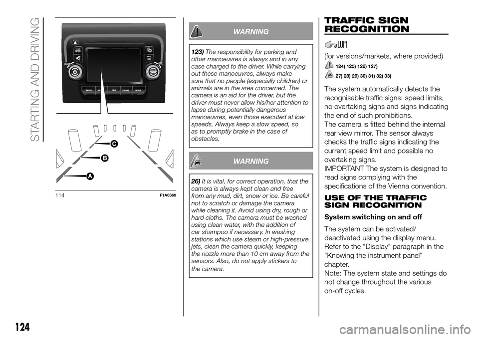
123)The responsibility for parking and
other manoeuvres is always and in any
case charged to the driver. While carrying
out these manoeuvres, always make
sure that no people (especially children) or
animals are in the area concerned. The
camera is an aid for the driver, but the
driver must never allow his/her attention to
lapse during potentially dangerous
manoeuvres, even those executed at low
speeds. Always keep a slow speed, so
as to promptly brake in the case of
obstacles.
WARNING
26)It is vital, for correct operation, that the
camera is always kept clean and free
from any mud, dirt, snow or ice. Be careful
not to scratch or damage the camera
while cleaning it. Avoid using dry, rough or
hard cloths. The camera must be washed
using clean water, with the addition of
car shampoo if necessary. In washing
stations which use steam or high-pressure
jets, clean the camera quickly, keeping
the nozzle more than 10 cm away from the
sensors. Also, do not apply stickers to
the camera.
TRAFFIC SIGN
RECOGNITION
(for versions/markets, where provided)
124) 125) 126) 127)
27) 28) 29) 30) 31) 32) 33)
The system automatically detects the
recognisable traffic signs: speed limits,
no overtaking signs and signs indicating
the end of such prohibitions.
The camera is fitted behind the internal
rear view mirror. The sensor always
checks the traffic signs indicating the
current speed limit and possible no
overtaking signs.
IMPORTANT The system is designed to
read signs complying with the
specifications of the Vienna convention.
USE OF THE TRAFFIC
SIGN RECOGNITION
System switching on and off
The system can be activated/
deactivated using the display menu.
Refer to the "Display" paragraph in the
"Knowing the instrument panel"
chapter.
Note: The system state and settings do
not change throughout the various
on-off cycles.
114F1A0360
124
STARTING AND DRIVING
Page 132 of 296
WARNING
128)Do not approach naked flames or lit
cigarettes to the fuel tank filler: fire risk.
Keep your face away from the fuel filler to
prevent breathing in harmful vapours.
129)To avoid fuel spillage and the
exceeding of the maximum level, avoid
topping up after filling the tank.
130)Any fuel pumping in portable
containers located on a floor can cause a
fire. Danger of burns. Always put the fuel
container on the ground during filling. Avoid
using contaminated fuel: a fuel
contaminated with water or earth can
cause serious damage to the motor supply.
Proper maintenance of the fuel filter, of
the engine and the fuel tank is essential.
131)If AdBlue overheats for a prolonged
period inside the tank to over 50 ° C (for
example due to direct solar irradiation),
AdBlue can decompose ammonia vapours.
Ammonia vapours have a pungent odour
when the cap of the AdBlue tank is
unscrewed, therefore be careful not to
inhale any ammonia vapours in the tank
outlet. In this concentration, however, the
ammonia vapors are not harmful or
dangerous to health.
132)Do not open the fuel system at high
pressure with the engine running. The
operation of the engine creates a high fuel
pressure. A jet of high-pressure fuel can
cause serious injury or death.
WARNING
34)Only refuel with automotive diesel
complying with the European specification
EN 590. The use of other products or
mixtures may damage the engine beyond
repair and consequently invalidate the
warranty, due to the damage caused. If
you accidentally introduce other types of
fuel into the tank, do not start the engine.
Empty the tank. If the engine has been run
for even an extremely limited amount of
time, you must not only drain the fuel tank,
but the rest of the supply circuit as well.
35)Methane refuelling stations are not
authorised to refill the cylinders when the
inspection date has expired. The check
valve prevents the methane from flowing
back to the fuel filler.
36)If the vehicle has been registered in a
country other than Italy, the certification
data, identification and inspection
procedures for the methane cylinders
should conform to the legislation in that
country. In any case, it should be
remembered that the life of the cylinders is
20 years from the production date as set
out in ECE Regulation no. 110.
ADDITIVE FOR
DIESEL EMISSIONS
ADBLUE (UREA)
The vehicle is equipped with a Selective
Catalytic Reduction system to meet
the strict Diesel emissions standards
required by the Agency for
Environmental Protection.
The purpose of the system of Selective
Catalytic Reduction is to reduce the
nitrogen oxides levels emitted by
engines; these elements are harmful to
our health and to the environment
even at minimum levels. A small
amount of additive for Diesel emissions
AdBlue (UREA) is injected upstream
of the catalyst exhaust outlet where,
when it turns into gas, converts
nitrogen oxides, that create smog, in
simple nitrogen and water vapour, two
natural components of air we breathe.
You can use your vehicle with the
peace of mind of knowing that you are
contributing to a cleaner and healthy
environment for future generations.
System description
The vehicle is equipped with an UREA
fuel injection system and a Selective
Catalytic Reduction catalyst to meet the
emission standards.
130
STARTING AND DRIVING