Plug FIAT DUCATO 2016 3.G Owners Manual
[x] Cancel search | Manufacturer: FIAT, Model Year: 2016, Model line: DUCATO, Model: FIAT DUCATO 2016 3.GPages: 296, PDF Size: 15.08 MB
Page 2 of 296
We really know your car because we invented, designed and built it: we really know every single detail.
At Fiat Service authorised workshopsyou can find technicians directly trained by us,
offering quality and professionalism for all service operations.
Fiat workshops are always close to you for the regular servicing operations, season checks
and practical recommendations by our experts.
With Original Parts distributed by MOPAR
®, you maintain the reliability, comfort
and performance features that you bought your new car for over time.
Always ask for Genuine Parts for the components used on our cars; we recommend them because
they come from our steady commitment in research and development of highly innovative technologies.
For all these reasons: rely on Genuine Parts, because they are the only ones designed
by FCA for your car.
SAFETY:
BRAKING SYSTEMENVIRONMENT: PARTICULATE FILTERS,
CLIMATE CONTROL MAINTENANCECOMFORT: SUSPENSION
AND WINDSCREEN WIPERS PERFORMANCE: SPARK PLUGS,
INJECTORS AND BATTERIESLINEACCESSORI
ROOF RACK BARS, WHEEL RIMS
WHY CHOOSING
GENUINE PARTS
This Owner Handbook is intended to show the vehicle's operating conditions.
For the enthusiast user who wants to have insights, curiosities and detailed information about the characteristics and functions
of the vehicle, Fiat gives the opportunity to consult a dedicated section which is available in electronic format.
ONLINE VEHICLE OWNER HANDBOOK
The following symbol is reported within the text of the Owner Handbook, next to the subjects for which details are provided.
Go to the www.mopar.eu/owner
website and access your personal area.
The “Maintenance and care” page includes all the information about your vehicle and the link to access eLUM, where you will find
all the details of the Owner Handbook.
Alternatively, to access this information, go to the Internet website at http://aftersales.fiat.com/elum/
.
The eLUMwebsite is free and will allow you, among many other things, to easily consult the on-board documents
of all the other vehicles of the Group.
Have a nice reading and happy motoring!
COP DUCATO LUM GB.qxp 21/12/16 16:55 Pagina 2
Page 49 of 296
KNOWING THE INSTRUMENT PANEL
This section of the booklet gives you all
the information you need to
understand, interpret and use the
instrument panel correctly.EOBD SYSTEM............................... 49
CONTROL PANEL AND
ON-BOARD INSTRUMENTS ........... 50
DISPLAY ........................................ 52
TRIP COMPUTER ........................... 54
WARNING LIGHTS AND
MESSAGES .................................... 56
- LOW BRAKE FLUID/HANDBRAKE
APPLIED ............................................ 56
- EBD FAILURE .................................. 57
- AIR BAG FAILURE ............................ 57
- SEAT BELTS REMINDER .................. 57
- ENGINE COOLANT TEMPERATURE
TOO HIGH .......................................... 58
- LOW BATTERY CHARGE ................. 59
- LOW ENGINE OIL PRESSURE ......... 60
-ENGINE OIL DETERIORATED ........... 60
-INCOMPLETE DOOR/LOAD
COMPARTMENT CLOSURE ............... 61
-POWER STEERING FAILURE ............ 61
- SELF-LEVELLING SUSPENSION
FAILURE ............................................. 61
- EOBD/INJECTION SYSTEM
FAILURE ............................................. 63
-UREA INJECTION SYSTEM FAILURE
............................................................ 64
-ABS FAILURE .................................... 64
- FUEL RESERVE ............................... 64
-GLOW PLUG PREHEATING / GLOW
PLUG PREHEATING FAILURE ............ 65
-LOW DIESEL EMISSIONS ADDITIVE
(UREA) LEVEL WARNING ................... 65
-VEHICLE PROTECTION SYSTEM
FAILURE - FIAT CODE ........................ 66
-REAR FOG LIGHTS ........................... 66
- GENERAL FAILURE WARNING ........ 67-DPF (PARTICULATE FILTER)
CLEANING UNDERWAY ..................... 68
- BRAKE PAD WEAR .......................... 68
-DRIVING ADVISOR ........................... 69
- TPMS ............................................... 70
-DIPPED BEAM HEADLIGHTS ........... 71
-FOLLOW ME HOME ......................... 71
- LEFT DIRECTION INDICATOR .......... 71
- RIGHT DIRECTION INDICATOR ....... 71
- FOG LIGHTS .................................... 72
- CRUISE CONTROL .......................... 72
- SPEED LIMITER ............................... 72
- AUTOMATIC MAIN BEAM
HEADLIGHTS ..................................... 72
- MAIN BEAM HEADLIGHTS .............. 72
-"UP" FUNCTION ............................... 73
-EXTERIOR LIGHTS FAILURE ............. 74
-LOW ENGINE OIL PRESSURE
WARNING LIGHT FAILURE ................. 74
-BRAKE LIGHTS FAILURE .................. 74
-MAIN BEAM AUTOMATISM FAULT ... 74
-POSSIBLE ICE ON ROAD ................. 75
-SPEED LIMIT EXCEEDED ................. 75
-SCHEDULED SERVICING ................. 75
-FUEL CUT-OFF DEVICE INERTIA
SWITCH TRIPPED .............................. 76
-COMFORT-MATIC SYSTEM FAILURE
INDICATION ........................................ 76
-PARKING SENSOR FAILURE ............ 76
-DRIVING ADVISOR SYSTEM
FAILURE ............................................. 76
-TRAFFIC SIGN RECOGNITION
FAILURE ............................................. 76
-LIMITED RANGE ............................... 76
-START&STOP SYSTEM
ACTIVATION/DEACTIVATION .............. 77
-START&STOP FAILURE .................... 77
47
Page 67 of 296
What it means What to do
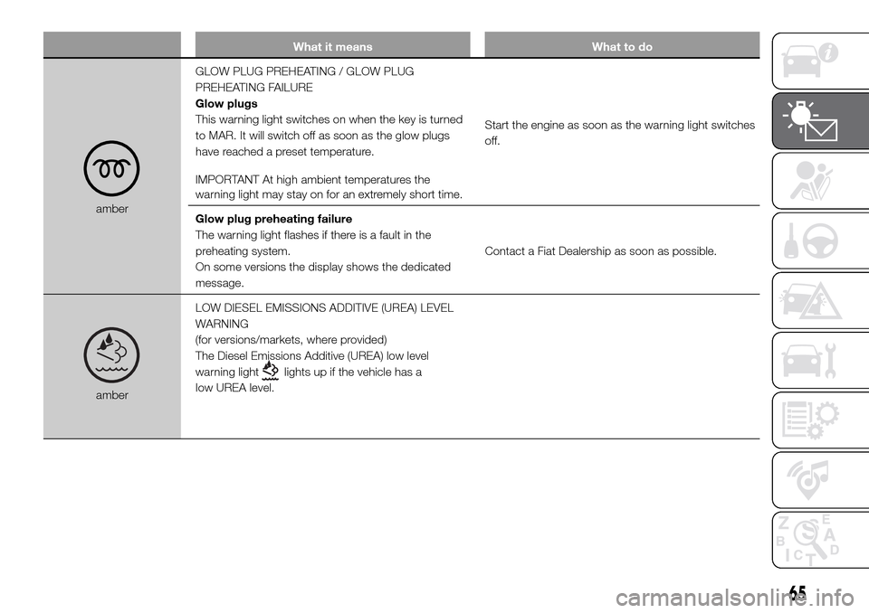
amberGLOW PLUG PREHEATING / GLOW PLUG
PREHEATING FAILURE
Glow plugs
This warning light switches on when the key is turned
to MAR. It will switch off as soon as the glow plugs
have reached a preset temperature.
IMPORTANT At high ambient temperatures the
warning light may stay on for an extremely short time.Start the engine as soon as the warning light switches
off.
Glow plug preheating failure
The warning light flashes if there is a fault in the
preheating system.
On some versions the display shows the dedicated
message.Contact a Fiat Dealership as soon as possible.
amberLOW DIESEL EMISSIONS ADDITIVE (UREA) LEVEL
WARNING
(for versions/markets, where provided)
The Diesel Emissions Additive (UREA) low level
warning light
lights up if the vehicle has a
low UREA level.
65
Page 117 of 296
STARTING THE
ENGINE
The vehicle is fitted with an electronic
engine lock device: if the engine fails to
start, see the paragraph “The Fiat
CODE system” in section “Know your
vehicle”.
Before starting the vehicle, adjust the
seat, the interior rear view mirrors,
the door mirrors and fasten the seat
belts correctly. Never press the
accelerator pedal for starting the
engine.
115)
14) 15)
PROCEDURE FOR
VERSIONS WITH MANUAL
TRANSMISSION
Proceed as follows:
engage the handbrake;
put the gear lever into neutral;
turn the ignition key to theMAR
position: the warning lights
and
on the instrument panel will turn on;
wait for the warning lightsand
to turn off, which will happen faster
the warmer the engine is;
fully depress the clutch pedal
without touching the accelerator;
turn the ignition key to the AVV
position as soon as the warning light
turns off. Waiting too long will waste
the heating work carried out by the
plugs.
Release the key as soon as the engine
starts.
PROCEDURE FOR
VERSIONS WITH
COMFORT MATIC
TRANSMISSION
The system allows the engine to be
started both with a gear engaged and
with the gearbox in neutral (N);
however, the brake pedal must be
pressed first with a gear engaged.
It is advisable to place the gear lever in
neutral (N) before starting the engine.
16)
PROCEDURE FOR
NATURAL POWER
VERSIONS
(For versions/markets, where provided)
The various engine cranking methods
are described below:
METHANE tank not on reserve –
petrol tank not empty:
the engine is always started in methane
mode;
METHANE tank empty – petrol tank
not empty:the engine is forced to start on petrol
and it will not switch to methane until
the methane tank has been filled. At the
same time, the reserve warning light
will turn on and the "REFUELLING
REQUIRED" message will be shown on
the instrument panel display;
METHANE tank not on reserve –
petrol tank empty:
the engine is always started in methane
mode.
17) 18) 19) 20) 21)
WARNING
115)It is dangerous to run the engine in
enclosed areas. The engine takes in
oxygen and releases carbon dioxide,
carbon monoxide and other toxic gases.
WARNING
14)It is advisable not to demand maximum
performance from your vehicle (e.g.
excessive acceleration, long distances at
high speeds, excessive intense braking,
etc.) during the initial period of use.
15)When the engine is switched off never
leave the key turned to MAR-ON to prevent
useless current absorption from draining
the battery.
115
Page 118 of 296
16)If the engine fails to start with a gear
engaged, the potentially dangerous
situation due to the fact that the
transmission is automatically placed in
neutral will be signalled by a buzzer.
17)If the warning light
flashes for 60
seconds after starting or during an
extended towing period, this indicates a
problem in the glow plug preheating
system. Use the vehicle normally if the
engine starts, but contact a Fiat Dealership
as soon as possible.
18)Remember that the brake servo and
power steering are not operational until the
engine has been started, so you need to
apply much more force than usual to
the brake pedal and steering wheel.
19)Never bump start the engine by
pushing, towing or coasting downhill. This
could cause fuel to flow into the catalytic
converter and damage it beyond repair.
20)A quick burst on the accelerator before
stopping the engine serves no practical
purpose; it wastes fuel and is especially
damaging to turbocharged engines.
21)In some cases, when the engine
switches off, the fan could activate for max.
120 seconds.
WHEN PARKED
116)
22)
Proceed as follows when parking and
leaving the vehicle:
engage the gear (on a slope, engage
first gear if the vehicle is facing uphill
or reverse if it is facing downhill) and
leave the wheels steered;
stop the engine and engage the
handbrake;
always remove the ignition key.
If the vehicle is parked on a steep
slope, it is advisable to block the
wheels with a wedge or stone.
On versions equipped with automatic
transmission (Comfort matic), wait
for the letterPto appear on the display
before releasing the brake pedal.
IMPORTANTNEVERleave the vehicle
with the gearbox in neutral (or, on
versions equipped with automatic
(Comfort matic) transmission, before
putting the shift lever in thePposition).HANDBRAKE
Handbrake engagement:The
handbrake lever is located to the left of
the driver's seat. Pull the lever upwards
to engage the handbrake and ensure
that the vehicle does not move.
Handbrake disengagement:slightly
raise the lever, hold the button A
pressed and check that the
warning light switches off on the
instrument panel.
Press the brake pedal when carrying
out this operation to prevent the vehicle
from moving accidentally.
WARNING
116)Never leave children unattended in
the vehicle. Always remove the ignition key
when leaving the vehicle and take it out
with you.
WARNING
22)If the vehicle is equipped with
self-levelling air suspension, always check
that there is sufficient space above the roof
and around the vehicle when parking.
Indeed, the vehicle could raise (or lower)
automatically depending on load or
temperature changes.
116
STARTING AND DRIVING
Page 124 of 296
PARKING SENSORS
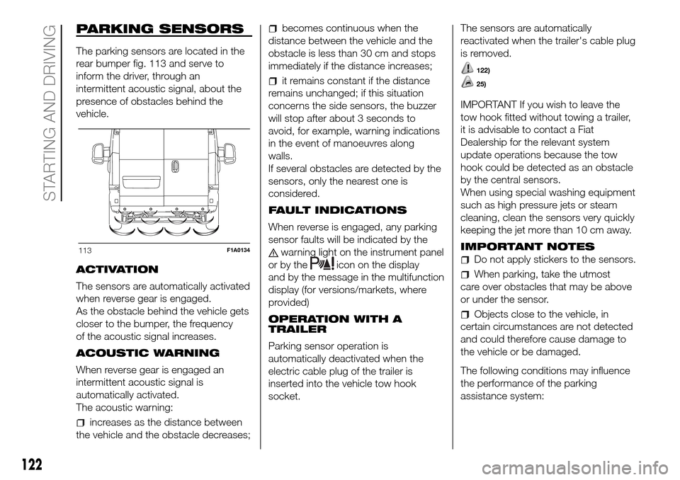
The parking sensors are located in the
rear bumper fig. 113 and serve to
inform the driver, through an
intermittent acoustic signal, about the
presence of obstacles behind the
vehicle.
ACTIVATION
The sensors are automatically activated
when reverse gear is engaged.
As the obstacle behind the vehicle gets
closer to the bumper, the frequency
of the acoustic signal increases.
ACOUSTIC WARNING
When reverse gear is engaged an
intermittent acoustic signal is
automatically activated.
The acoustic warning:
increases as the distance between
the vehicle and the obstacle decreases;
becomes continuous when the
distance between the vehicle and the
obstacle is less than 30 cm and stops
immediately if the distance increases;
it remains constant if the distance
remains unchanged; if this situation
concerns the side sensors, the buzzer
will stop after about 3 seconds to
avoid, for example, warning indications
in the event of manoeuvres along
walls.
If several obstacles are detected by the
sensors, only the nearest one is
considered.
FAULT INDICATIONS
When reverse is engaged, any parking
sensor faults will be indicated by the
warning light on the instrument panel
or by the
icon on the display
and by the message in the multifunction
display (for versions/markets, where
provided)
OPERATION WITH A
TRAILER
Parking sensor operation is
automatically deactivated when the
electric cable plug of the trailer is
inserted into the vehicle tow hook
socket.The sensors are automatically
reactivated when the trailer's cable plug
is removed.
122)
25)
IMPORTANT If you wish to leave the
tow hook fitted without towing a trailer,
it is advisable to contact a Fiat
Dealership for the relevant system
update operations because the tow
hook could be detected as an obstacle
by the central sensors.
When using special washing equipment
such as high pressure jets or steam
cleaning, clean the sensors very quickly
keeping the jet more than 10 cm away.
IMPORTANT NOTES
Do not apply stickers to the sensors.
When parking, take the utmost
care over obstacles that may be above
or under the sensor.
Objects close to the vehicle, in
certain circumstances are not detected
and could therefore cause damage to
the vehicle or be damaged.
The following conditions may influence
the performance of the parking
assistance system:
113F1A0134
122
STARTING AND DRIVING
Page 141 of 296
INSTRUCTIONS FOR
USING THE REMOVABLE
BALL HEAD TOW BAR
40) 41) 42) 43) 44) 45)Before setting off, check the correct
locking of the removable ball head tow
bar, as follows:
The green mark of the flywheel must
coincide with the green mark on the
tow bar.
The flywheel is in the stop position
on the tow bar (without slot).
Locked lock and key removed. The
flywheel cannot be removed.
Ball head bar firmly secured to the
housing pipe. Check by shaking with a
hand.
The fitting procedure must be repeated
if any of the 4 checked requirements
is not met.
If even only one of the requirements is
not met the tow hook must not be
used, as in this case there is risk of
accidents. Contact the joint
manufacturer.
The ball head tow bar can be fitted and
removed manually, without needing
any tool.
Never use working tools or means, as
the mechanism could be damaged.
Never unlock in the case of trailer
attached to the vehicle or fitted rack.When driving without trailer or rack the
ball head tow bar must be removed
and the closing plug must always
be inserted in the housing pipe. This
applies particularly if the visibility of the
number plate characters or of the
lighting system is reduced.
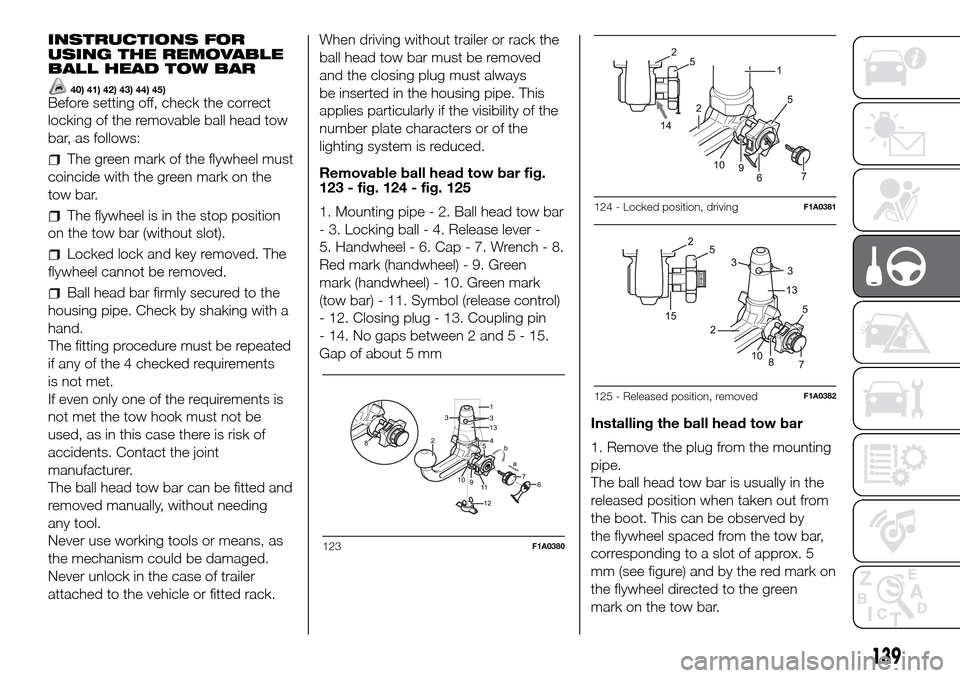
Removable ball head tow bar fig.
123 - fig. 124 - fig. 125
1. Mounting pipe - 2. Ball head tow bar
- 3. Locking ball - 4. Release lever -
5. Handwheel - 6. Cap - 7. Wrench - 8.
Red mark (handwheel) - 9. Green
mark (handwheel) - 10. Green mark
(tow bar) - 11. Symbol (release control)
- 12. Closing plug - 13. Coupling pin
- 14. No gaps between 2 and5-15.
Gap of about 5 mm
Installing the ball head tow bar
1. Remove the plug from the mounting
pipe.
The ball head tow bar is usually in the
released position when taken out from
the boot. This can be observed by
the flywheel spaced from the tow bar,
corresponding to a slot of approx. 5
mm (see figure) and by the red mark on
the flywheel directed to the green
mark on the tow bar.
123F1A0380
124 - Locked position, drivingF1A0381
125 - Released position, removedF1A0382
139
Page 142 of 296
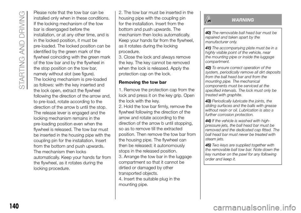
Please note that the tow bar can be
installed only when in these conditions.
If the locking mechanism of the tow
bar is disengaged before the
installation, or at any other time, and is
in the locked position, it must be
pre-loaded. The locked position can be
identified by the green mark of the
flywheel coinciding with the green mark
of the tow bar and by the flywheel in
the stop position on the tow bar,
namely without slot (see figure).
The locking mechanism is pre-loaded
as follows: with the key inserted and
the lock open, extract the flywheel
following the direction of the arrow and,
to pre-load, rotate according to the
direction of the arrow b until the stop.
The release lever is engaged and the
locking mechanism remains in the
pre-loading position even when the
flywheel is released. The tow bar must
be inserted in the housing pipe with the
coupling pin for the installation. Insert
from the bottom and push upwards.
The mechanism then locks
automatically. Keep your hands far from
the flywheel, as it rotates during the
locking procedure.2. The tow bar must be inserted in the
housing pipe with the coupling pin
for the installation. Insert from the
bottom and push upwards. The
mechanism then locks automatically.
Keep your hands far from the flywheel,
as it rotates during the locking
procedure.
3. Close the lock and always remove
the key. The key cannot be removed
when the lock is released. Apply the
protection cap on the lock.
Removing the tow bar
1. Remove the protection cap from the
lock and press it on the key grip. Open
the lock with the key.
2. Hold the tow bar firmly, remove the
flywheel following the direction of the
arrow and rotate according to the
direction of the arrow b until stopping,
so as to remove till the extracted
position. Then remove the tow bar from
the housing pipe. The flywheel can
then be released; it autonomously
stops in the released position.
3. Arrange the tow bar in the luggage
compartment so that it cannot be
dirtied or damaged by other
transported objects.
4. Insert the suitable plug in the
mounting pipe.
WARNING
40)The removable ball head bar must be
repaired and taken apart by the
manufacturer only.
41)The accompanying plate must be in a
highly visible point of the vehicle, near
the mounting pipe or inside the luggage
compartment.
42)To ensure correct operation of the
system, periodically remove all dirt deposits
from the ball head bar and from the
mounting pipe. The mechanical
components must be serviced at the
specified intervals. The lock must only be
treated with graphite.
43)Periodically lubricate the joints, the
sliding surfaces and the balls with grease
without resin or oil. Lubrication is also a
further corrosion protection.
44)If the vehicle is washed with high-
pressure jets, the ball head bar must be
removed and the dedicated cap fitted. The
ball head bar must never be treated with
steam jets.
45)Two keys are supplied together with
the removable ball tow bar. Note down the
key number on the pawl for any following
order and keep it.
140
STARTING AND DRIVING
Page 177 of 296
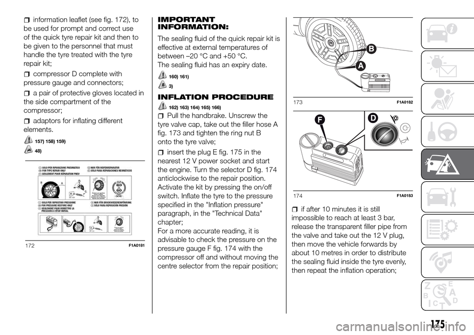
information leaflet (see fig. 172), to
be used for prompt and correct use
of the quick tyre repair kit and then to
be given to the personnel that must
handle the tyre treated with the tyre
repair kit;
compressor D complete with
pressure gauge and connectors;
a pair of protective gloves located in
the side compartment of the
compressor;
adaptors for inflating different
elements.
157) 158) 159)
48)
IMPORTANT
INFORMATION:
The sealing fluid of the quick repair kit is
effective at external temperatures of
between –20 °C and +50 °C.
The sealing fluid has an expiry date.
160) 161)
3)
INFLATION PROCEDURE
162) 163) 164) 165) 166)
Pull the handbrake. Unscrew the
tyre valve cap, take out the filler hose A
fig. 173 and tighten the ring nut B
onto the tyre valve;
insert the plug E fig. 175 in the
nearest 12 V power socket and start
the engine. Turn the selector D fig. 174
anticlockwise to the repair position.
Activate the kit by pressing the on/off
switch. Inflate the tyre to the pressure
specified in the "Inflation pressure"
paragraph, in the "Technical Data"
chapter;
For a more accurate reading, it is
advisable to check the pressure on the
pressure gauge F fig. 174 with the
compressor off and without moving the
centre selector from the repair position;
if after 10 minutes it is still
impossible to reach at least 3 bar,
release the transparent filler pipe from
the valve and take out the 12 V plug,
then move the vehicle forwards by
about 10 metres in order to distribute
the sealing fluid inside the tyre evenly,
then repeat the inflation operation;
172F1A0181
173F1A0182
174F1A0183
175
Page 192 of 296
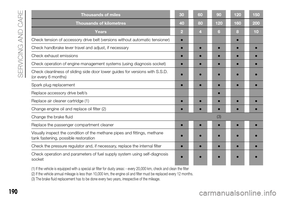
Thousands of kilometres 40 80 120 160 200
Years246810
Check tension of accessory drive belt (versions without automatic tensioner)●●
Check handbrake lever travel and adjust, if necessary●●●●●
Check exhaust emissions●●●●●
Check operation of engine management systems (using diagnosis socket)●●●●●
Check cleanliness of sliding side door lower guides for versions with S.S.D.
(or every 6 months)●●●●●
Spark plug replacement●●●●●
Replace accessory drive belt/s●
Replace air cleaner cartridge (1)●●●●●
Change engine oil and replace oil filter (2)●●●●●
Change the brake fluid(3)
Replace the passenger compartment cleaner●●●●●
Visually inspect the condition of the methane pipes and fittings, methane
tank fastening, possible restoration●●●●●
Check the pressure regulator and, if necessary, replace the internal filter●●●●●
Check operation and parameters of fuel supply system using self-diagnosis
socket●●●●●
(1) If the vehicle is equipped with a special air filter for dusty areas: - every 20,000 km, check and clean the filter
(2) If the vehicle annual mileage is less than 10,000 km, the engine oil and filter must be replaced every 12 months.
(3) The brake fluid replacement has to be done every two years, irrespective of the mileage.
190
SERVICING AND CARE
Thousands of miles 30 60 90 120 150