driving FIAT DUCATO 2018 Owner handbook (in English)
[x] Cancel search | Manufacturer: FIAT, Model Year: 2018, Model line: DUCATO, Model: FIAT DUCATO 2018Pages: 304, PDF Size: 14.93 MB
Page 29 of 304
WARNING
29)As the driver's exterior mirror is curved,
it may slightly alter the perception of
distance of the reflected image. Further,
the reflective surface of the lower part
of the exterior mirrors is parabolic to
increase the field of view. The reflected
image size is thus reduced and gives the
impression that the reflected item is further
away than it actually is.
30)When driving the mirrors should always
remain in position 1.
EXTERIOR LIGHTS
IN BRIEF
The left stalk includes the controls for
the exterior lights.
Theexterior lights can only be
switched on when the ignition key is
in the ON position.
LIGHTS OFF
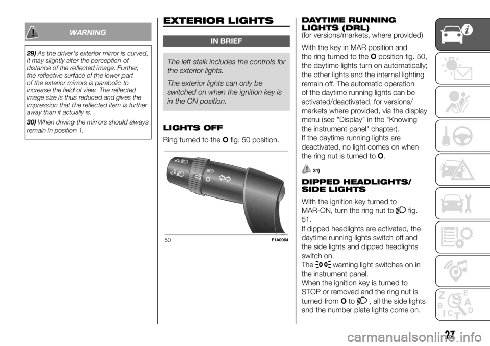
Ring turned to theOfig. 50 position.DAYTIME RUNNING
LIGHTS (DRL)
(for versions/markets, where provided)
With the key in MAR position and
the ring turned to theOposition fig. 50,
the daytime lights turn on automatically;
the other lights and the internal lighting
remain off. The automatic operation
of the daytime running lights can be
activated/deactivated, for versions/
markets where provided, via the display
menu (see "Display" in the "Knowing
the instrument panel" chapter).
If the daytime running lights are
deactivated, no light comes on when
the ring nut is turned toO.
31)
DIPPED HEADLIGHTS/
SIDE LIGHTS
With the ignition key turned to
MAR-ON, turn the ring nut to
fig.
51.
If dipped headlights are activated, the
daytime running lights switch off and
the side lights and dipped headlights
switch on.
The
warning light switches on in
the instrument panel.
When the ignition key is turned to
STOP or removed and the ring nut is
turned fromOto
, all the side lights
and the number plate lights come on.
50F1A0064
27
Page 30 of 304
Thewarning light will come on in
the instrument panel.
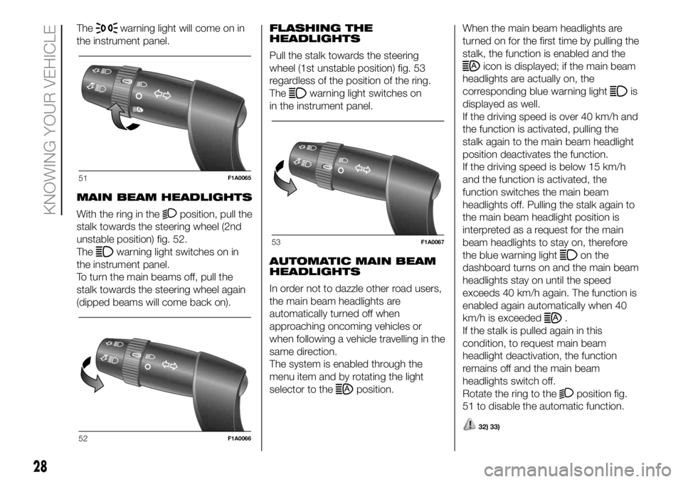
MAIN BEAM HEADLIGHTS
With the ring in the
position, pull the
stalk towards the steering wheel (2nd
unstable position) fig. 52.
The
warning light switches on in
the instrument panel.
To turn the main beams off, pull the
stalk towards the steering wheel again
(dipped beams will come back on).FLASHING THE
HEADLIGHTS
Pull the stalk towards the steering
wheel (1st unstable position) fig. 53
regardless of the position of the ring.
The
warning light switches on
in the instrument panel.
AUTOMATIC MAIN BEAM
HEADLIGHTS
In order not to dazzle other road users,
the main beam headlights are
automatically turned off when
approaching oncoming vehicles or
when following a vehicle travelling in the
same direction.
The system is enabled through the
menu item and by rotating the light
selector to the
position.When the main beam headlights are
turned on for the first time by pulling the
stalk, the function is enabled and the
icon is displayed; if the main beam
headlights are actually on, the
corresponding blue warning light
is
displayed as well.
If the driving speed is over 40 km/h and
the function is activated, pulling the
stalk again to the main beam headlight
position deactivates the function.
If the driving speed is below 15 km/h
and the function is activated, the
function switches the main beam
headlights off. Pulling the stalk again to
the main beam headlight position is
interpreted as a request for the main
beam headlights to stay on, therefore
the blue warning light
on the
dashboard turns on and the main beam
headlights stay on until the speed
exceeds 40 km/h again. The function is
enabled again automatically when 40
km/h is exceeded
.
If the stalk is pulled again in this
condition, to request main beam
headlight deactivation, the function
remains off and the main beam
headlights switch off.
Rotate the ring to the
position fig.
51 to disable the automatic function.
32) 33)
51F1A0065
52F1A0066
53F1A0067
28
KNOWING YOUR VEHICLE
Page 32 of 304
Activation
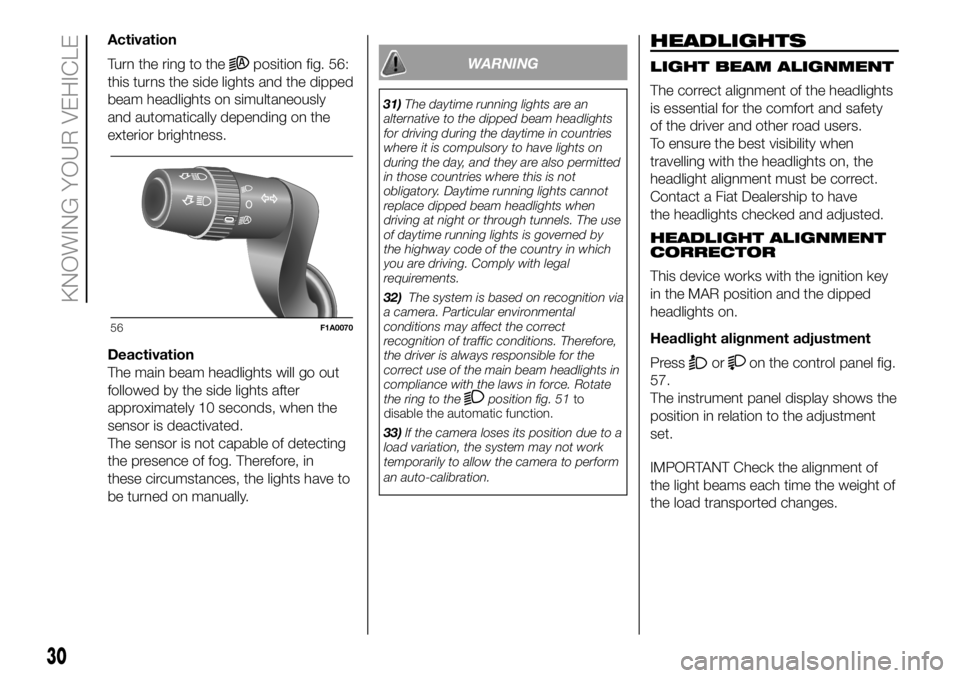
Turn the ring to the
position fig. 56:
this turns the side lights and the dipped
beam headlights on simultaneously
and automatically depending on the
exterior brightness.
Deactivation
The main beam headlights will go out
followed by the side lights after
approximately 10 seconds, when the
sensor is deactivated.
The sensor is not capable of detecting
the presence of fog. Therefore, in
these circumstances, the lights have to
be turned on manually.WARNING
31)The daytime running lights are an
alternative to the dipped beam headlights
for driving during the daytime in countries
where it is compulsory to have lights on
during the day, and they are also permitted
in those countries where this is not
obligatory. Daytime running lights cannot
replace dipped beam headlights when
driving at night or through tunnels. The use
of daytime running lights is governed by
the highway code of the country in which
you are driving. Comply with legal
requirements.
32)The system is based on recognition via
a camera. Particular environmental
conditions may affect the correct
recognition of traffic conditions. Therefore,
the driver is always responsible for the
correct use of the main beam headlights in
compliance with the laws in force. Rotate
the ring to the
position fig. 51to
disable the automatic function.
33)If the camera loses its position due to a
load variation, the system may not work
temporarily to allow the camera to perform
an auto-calibration.
HEADLIGHTS
LIGHT BEAM ALIGNMENT
The correct alignment of the headlights
is essential for the comfort and safety
of the driver and other road users.
To ensure the best visibility when
travelling with the headlights on, the
headlight alignment must be correct.
Contact a Fiat Dealership to have
the headlights checked and adjusted.
HEADLIGHT ALIGNMENT
CORRECTOR
This device works with the ignition key
in the MAR position and the dipped
headlights on.
Headlight alignment adjustment
Press
oron the control panel fig.
57.
The instrument panel display shows the
position in relation to the adjustment
set.
IMPORTANT Check the alignment of
the light beams each time the weight of
the load transported changes.
56F1A0070
30
KNOWING YOUR VEHICLE
Page 35 of 304
PARKING LIGHTS
These lights can only be turned on with
ignition key in the STOP position or
removed by moving the left stalk ring
first to theOposition and then to the
orposition. Thewarning
light switches on in the instrument
panel.
ECO FUNCTION
(For versions/markets, where provided)
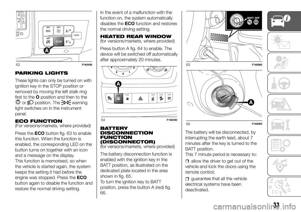
Press theECObutton fig. 63 to enable
this function. When the function is
enabled, the corresponding LED on the
button turns on together with an icon
and a message on the display.
This function is memorised, so when
the vehicle is started again, the system
keeps the setting it had before the
engine was stopped. Press theECO
button again to disable the function and
restore the normal driving setting.In the event of a malfunction with the
function on, the system automatically
disables theECOfunction and restores
the normal driving setting.
HEATED REAR WINDOW
(for versions/markets, where provided)
Press button A fig. 64 to enable. The
device will be switched off automatically
after approximately 20 minutes.
BATTERY
DISCONNECTION
FUNCTION
(DISCONNECTOR)
(for versions/markets, where provided)
The battery disconnection function is
enabled with the ignition key in the
BATT position, as illustrated on the
dedicated plate located in the area
shown in fig. 65.
To turn the ignition key to BATT
position, press the button A (red) fig.
66.The battery will be disconnected, by
interrupting the earth lead, about 7
minutes after the key is turned to the
BATT position.
This 7 minute period is necessary to:
allow the driver to get out of the
vehicle and lock the doors using the
remote control;
guarantee that all the vehicle
electrical systems have been
deactivated.
MODE
63F1A0438
64F1A0330
65F1A0082
66F1A0083
33
Page 37 of 304
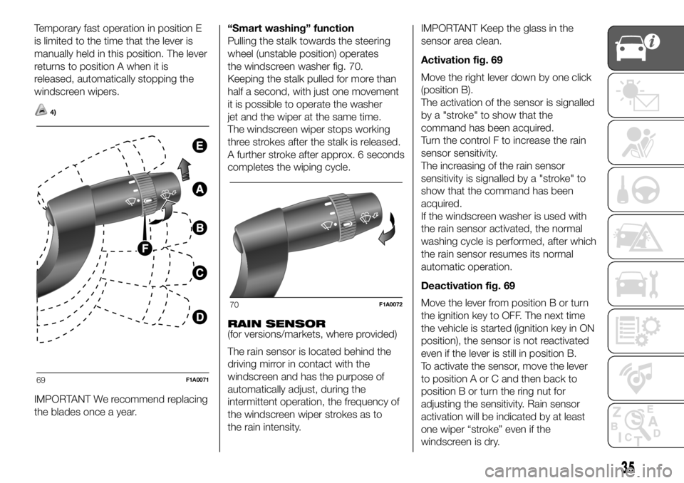
Temporary fast operation in position E
is limited to the time that the lever is
manually held in this position. The lever
returns to position A when it is
released, automatically stopping the
windscreen wipers.
4)
IMPORTANT We recommend replacing
the blades once a year.“Smart washing” function
Pulling the stalk towards the steering
wheel (unstable position) operates
the windscreen washer fig. 70.
Keeping the stalk pulled for more than
half a second, with just one movement
it is possible to operate the washer
jet and the wiper at the same time.
The windscreen wiper stops working
three strokes after the stalk is released.
A further stroke after approx. 6 seconds
completes the wiping cycle.
RAIN SENSOR
(for versions/markets, where provided)
The rain sensor is located behind the
driving mirror in contact with the
windscreen and has the purpose of
automatically adjust, during the
intermittent operation, the frequency of
the windscreen wiper strokes as to
the rain intensity.IMPORTANT Keep the glass in the
sensor area clean.
Activation fig. 69
Move the right lever down by one click
(position B).
The activation of the sensor is signalled
by a "stroke" to show that the
command has been acquired.
Turn the control F to increase the rain
sensor sensitivity.
The increasing of the rain sensor
sensitivity is signalled by a "stroke" to
show that the command has been
acquired.
If the windscreen washer is used with
the rain sensor activated, the normal
washing cycle is performed, after which
the rain sensor resumes its normal
automatic operation.
Deactivation fig. 69
Move the lever from position B or turn
the ignition key to OFF. The next time
the vehicle is started (ignition key in ON
position), the sensor is not reactivated
even if the lever is still in position B.
To activate the sensor, move the lever
to position A or C and then back to
position B or turn the ring nut for
adjusting the sensitivity. Rain sensor
activation will be indicated by at least
one wiper “stroke” even if the
windscreen is dry.
69F1A0071
70F1A0072
35
Page 44 of 304

Programming the switching on time
To program the activation time:
press button 4: the symbol 10 or the
time set previously and the number 5
corresponding to the preselection
recalled will light up in the display for 10
seconds.
IMPORTANT If you wish to recall other
preselected times, press button 4
from time to time within 10 seconds.
– within 10 seconds, press the buttons
3 or 8 to select the desired switching
on time.
IMPORTANT The confirmation that the
time has been memorised is given by:
the disappearance of the switching
on time;
the presence of the preselection
number 5;
the lighting of the display.
IMPORTANT When the boiler comes
on:
the flame warning light 9 switches
on in the display;
the preselection number 5 goes out.
Standard settings:
Preselected time 1: 6:00
Preselected time 2: 16:00
Preselected time 3: 22:00IMPORTANT Factory pre-settings are
cancelled with a new setting.
Preselected times are stored until the
following change. If the clock is
detached from the on-board network
(e.g. if the battery is disconnected), the
factory pre-settings are restored.
Deactivation of the programmed
switching on time
To delete the programmed activation
time, press button 4 briefly: the display
lighting will go off and the number 5
relating to the preselected time will
disappear.
Recalling one of the preselected
switching on times
Operate button 4 within 10 seconds
until the program number with the
desired preselected time is displayed.
The preselected time you have chosen
to set is automatically activated after
about 10 seconds without the need for
any further confirmation with another
button.
Activate the preselected time taking
into account the safety instructions for
the operation of the independent
heating (for this purpose consult the
Owner's Manual for use of independent
heating).IMPORTANT Independent heating
switches on at the preselected time,
both with vehicle parked and while
driving.
IMPORTANT The programmed
switching on time can be altered or
cancelled by following the instructions
given previously.
Operation duration setting
Hold the button pressed. At the same
time press button 3 or 8.
The time and warning light 7 are
displayed.
Press the button 4 again and hold it
down. At the same time press the
button 3 or 8.
The preset activation duration is
displayed and warning light 9 or 2
flashes.
Set the activation duration with button
3or8.
The set activation duration is stored as
soon as the text in the display
disappears, or pressing button 4.
Switching the heating system off
Deactivation of the system, depending
on the type of activation (automatic
or manual), may be:
automaticwhen the programmed
duration is over; when the set time is
over, the display switches off.
42
KNOWING YOUR VEHICLE
Page 48 of 304
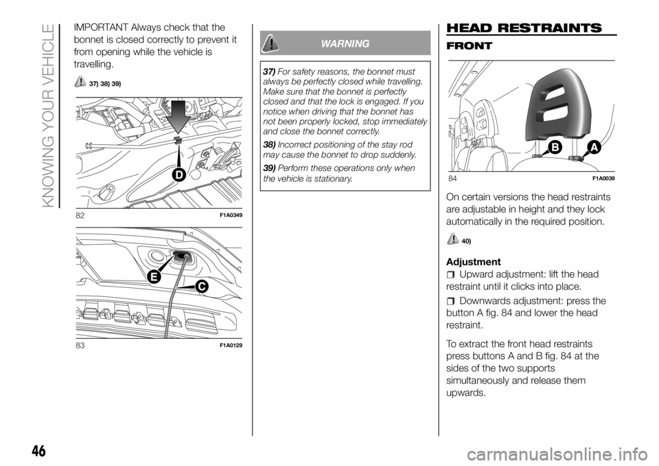
IMPORTANT Always check that the
bonnet is closed correctly to prevent it
from opening while the vehicle is
travelling.
37) 38) 39)
WARNING
37)For safety reasons, the bonnet must
always be perfectly closed while travelling.
Make sure that the bonnet is perfectly
closed and that the lock is engaged. If you
notice when driving that the bonnet has
not been properly locked, stop immediately
and close the bonnet correctly.
38)Incorrect positioning of the stay rod
may cause the bonnet to drop suddenly.
39)Perform these operations only when
the vehicle is stationary.
HEAD RESTRAINTS
FRONT
On certain versions the head restraints
are adjustable in height and they lock
automatically in the required position.
40)
Adjustment
Upward adjustment: lift the head
restraint until it clicks into place.
Downwards adjustment: press the
button A fig. 84 and lower the head
restraint.
To extract the front head restraints
press buttons A and B fig. 84 at the
sides of the two supports
simultaneously and release them
upwards.
82F1A0349
83F1A0129
84F1A0039
46
KNOWING YOUR VEHICLE
Page 50 of 304
TABLET HOLDER
(for versions/markets, where provided)
It is located in the centre of the
dashboard and is designed to anchor a
tablet.
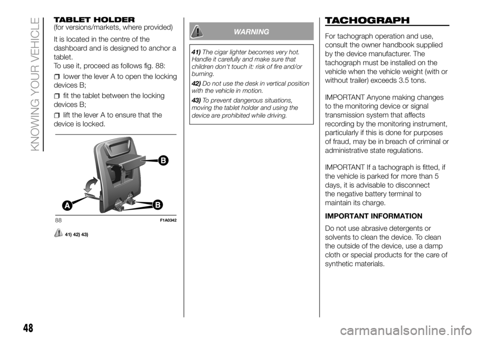
To use it, proceed as follows fig. 88:
lower the lever A to open the locking
devices B;
fit the tablet between the locking
devices B;
lift the lever A to ensure that the
device is locked.
41) 42) 43)
WARNING
41)The cigar lighter becomes very hot.
Handle it carefully and make sure that
children don't touch it: risk of fire and/or
burning.
42)Do not use the desk in vertical position
with the vehicle in motion.
43)To prevent dangerous situations,
moving the tablet holder and using the
device are prohibited while driving.
TACHOGRAPH
For tachograph operation and use,
consult the owner handbook supplied
by the device manufacturer. The
tachograph must be installed on the
vehicle when the vehicle weight (with or
without trailer) exceeds 3.5 tons.
IMPORTANT Anyone making changes
to the monitoring device or signal
transmission system that affects
recording by the monitoring instrument,
particularly if this is done for purposes
of fraud, may be in breach of criminal or
administrative state regulations.
IMPORTANT If a tachograph is fitted, if
the vehicle is parked for more than 5
days, it is advisable to disconnect
the negative battery terminal to
maintain its charge.
IMPORTANT INFORMATION
Do not use abrasive detergents or
solvents to clean the device. To clean
the outside of the device, use a damp
cloth or special products for the care of
synthetic materials.
88F1A0342
48
KNOWING YOUR VEHICLE
Page 51 of 304
The tachograph is installed and sealed
by authorised personnel: do not try
and access the device or the supply
and recording leads in any way. It is the
responsibility of the owner of the vehicle
on which the tachograph is installed to
check the device regularly.
The check must be carried out at least
every two years and a test must be
carried out to ensure that it is working
properly. Ensure that the data label
is renewed after every check and that
the label contains the specified data.SELF-LEVELLING AIR
SUSPENSION
GENERAL INFORMATION
The system only acts on the rear
wheels.
The system maintains the rear ride
setting for the vehicle constant in any
loading condition, while ensuring a
greater driving comfort.
HEIGHT ADJUSTMENT
There are 7 pre-defined levels for the
free height from the ground: from “ride
-3” to “ride 0” till “ride +3”.
The trim is shown on the multifunction
display
Automatic adjustment
When moving, the system automatically
shows that the vehicle is in 'ride setting
0' and keeps it constant.
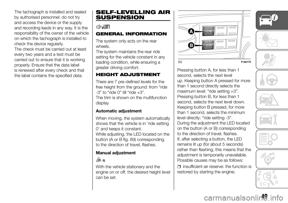
While adjusting, the LED located on the
button (A or B fig. 89) corresponding
to the direction of travel, flashes.
Manual adjustment
5)
With the vehicle stationary and the
engine on or off, the desired height level
can be set.Pressing button A, for less than 1
second, selects the next level
up. Keeping button A pressed for more
than 1 second directly selects the
maximum level: "ride setting +3".
Pressing button B, for less than 1
second, selects the next level down.
Keeping button B pressed, for more
than 1 second, selects the minimum
level directly: "ride setting -3".
During the adjustment the LED located
on the button (A or B) corresponding
to the direction of travel, flashes.
If, after selecting a button, the LED
remains lit up (for about 5 seconds)
rather than flashing, this means that the
adjustment is temporarily unavailable.
Possible causes may be as follows:insufficient air reserve: the function is
restored by starting the engine;
89F1A0170
49
Page 53 of 304
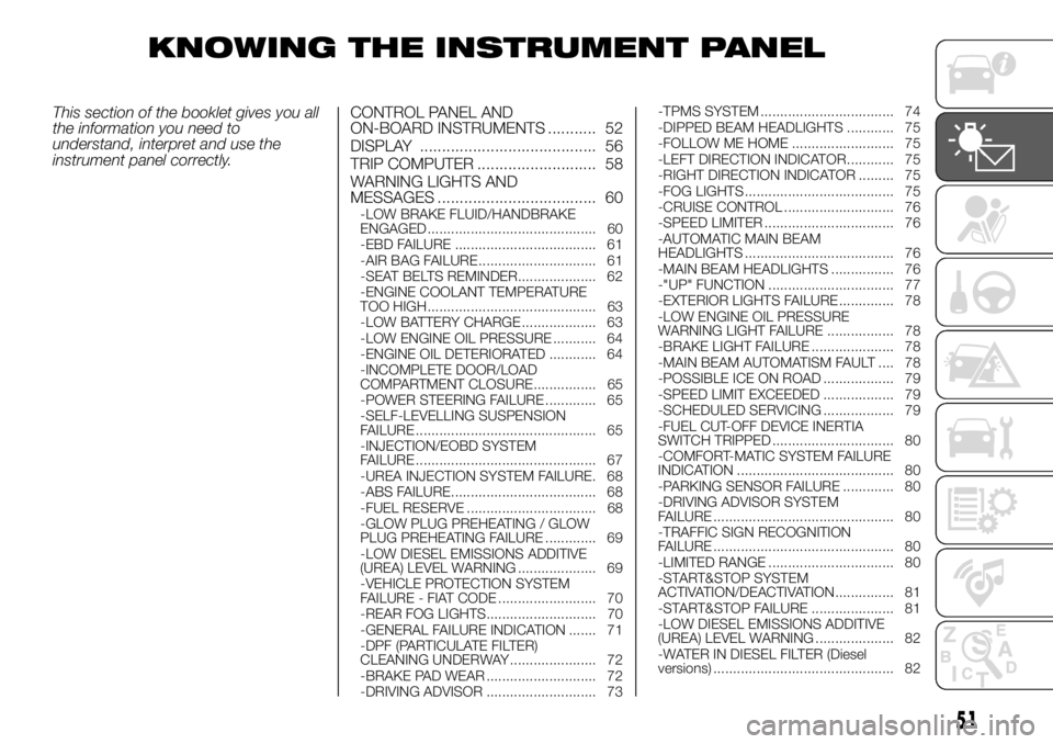
KNOWING THE INSTRUMENT PANEL
This section of the booklet gives you all
the information you need to
understand, interpret and use the
instrument panel correctly.CONTROL PANEL AND
ON-BOARD INSTRUMENTS ........... 52
DISPLAY ........................................ 56
TRIP COMPUTER ........................... 58
WARNING LIGHTS AND
MESSAGES .................................... 60
-LOW BRAKE FLUID/HANDBRAKE
ENGAGED........................................... 60
-EBD FAILURE .................................... 61
-AIR BAG FAILURE .............................. 61
-SEAT BELTS REMINDER.................... 62
-ENGINE COOLANT TEMPERATURE
TOO HIGH........................................... 63
-LOW BATTERY CHARGE ................... 63
-LOW ENGINE OIL PRESSURE ........... 64
-ENGINE OIL DETERIORATED ............ 64
-INCOMPLETE DOOR/LOAD
COMPARTMENT CLOSURE................ 65
-POWER STEERING FAILURE ............. 65
-SELF-LEVELLING SUSPENSION
FAILURE .............................................. 65
-INJECTION/EOBD SYSTEM
FAILURE .............................................. 67
-UREA INJECTION SYSTEM FAILURE. 68
-ABS FAILURE..................................... 68
-FUEL RESERVE ................................. 68
-GLOW PLUG PREHEATING / GLOW
PLUG PREHEATING FAILURE ............. 69
-LOW DIESEL EMISSIONS ADDITIVE
(UREA) LEVEL WARNING .................... 69
-VEHICLE PROTECTION SYSTEM
FAILURE - FIAT CODE ......................... 70
-REAR FOG LIGHTS............................ 70
-GENERAL FAILURE INDICATION ....... 71
-DPF (PARTICULATE FILTER)
CLEANING UNDERWAY ...................... 72
-BRAKE PAD WEAR ............................ 72
-DRIVING ADVISOR ............................ 73-TPMS SYSTEM .................................. 74
-DIPPED BEAM HEADLIGHTS ............ 75
-FOLLOW ME HOME .......................... 75
-LEFT DIRECTION INDICATOR ............ 75
-RIGHT DIRECTION INDICATOR ......... 75
-FOG LIGHTS ...................................... 75
-CRUISE CONTROL ............................ 76
-SPEED LIMITER ................................. 76
-AUTOMATIC MAIN BEAM
HEADLIGHTS ...................................... 76
-MAIN BEAM HEADLIGHTS ................ 76
-"UP" FUNCTION ................................ 77
-EXTERIOR LIGHTS FAILURE .............. 78
-LOW ENGINE OIL PRESSURE
WARNING LIGHT FAILURE ................. 78
-BRAKE LIGHT FAILURE ..................... 78
-MAIN BEAM AUTOMATISM FAULT .... 78
-POSSIBLE ICE ON ROAD .................. 79
-SPEED LIMIT EXCEEDED .................. 79
-SCHEDULED SERVICING .................. 79
-FUEL CUT-OFF DEVICE INERTIA
SWITCH TRIPPED ............................... 80
-COMFORT-MATIC SYSTEM FAILURE
INDICATION ........................................ 80
-PARKING SENSOR FAILURE ............. 80
-DRIVING ADVISOR SYSTEM
FAILURE .............................................. 80
-TRAFFIC SIGN RECOGNITION
FAILURE .............................................. 80
-LIMITED RANGE ................................ 80
-START&STOP SYSTEM
ACTIVATION/DEACTIVATION............... 81
-START&STOP FAILURE ..................... 81
-LOW DIESEL EMISSIONS ADDITIVE
(UREA) LEVEL WARNING .................... 82
-WATER IN DIESEL FILTER (Diesel
versions) .............................................. 82
51