light FIAT DUCATO 2018 Owner handbook (in English)
[x] Cancel search | Manufacturer: FIAT, Model Year: 2018, Model line: DUCATO, Model: FIAT DUCATO 2018Pages: 304, PDF Size: 14.93 MB
Page 44 of 304
Programming the switching on time
To program the activation time:
press button 4: the symbol 10 or the
time set previously and the number 5
corresponding to the preselection
recalled will light up in the display for 10
seconds.
IMPORTANT If you wish to recall other
preselected times, press button 4
from time to time within 10 seconds.
– within 10 seconds, press the buttons
3 or 8 to select the desired switching
on time.
IMPORTANT The confirmation that the
time has been memorised is given by:
the disappearance of the switching
on time;
the presence of the preselection
number 5;
the lighting of the display.
IMPORTANT When the boiler comes
on:
the flame warning light 9 switches
on in the display;
the preselection number 5 goes out.
Standard settings:
Preselected time 1: 6:00
Preselected time 2: 16:00
Preselected time 3: 22:00IMPORTANT Factory pre-settings are
cancelled with a new setting.
Preselected times are stored until the
following change. If the clock is
detached from the on-board network
(e.g. if the battery is disconnected), the
factory pre-settings are restored.
Deactivation of the programmed
switching on time
To delete the programmed activation
time, press button 4 briefly: the display
lighting will go off and the number 5
relating to the preselected time will
disappear.
Recalling one of the preselected
switching on times
Operate button 4 within 10 seconds
until the program number with the
desired preselected time is displayed.
The preselected time you have chosen
to set is automatically activated after
about 10 seconds without the need for
any further confirmation with another
button.
Activate the preselected time taking
into account the safety instructions for
the operation of the independent
heating (for this purpose consult the
Owner's Manual for use of independent
heating).IMPORTANT Independent heating
switches on at the preselected time,
both with vehicle parked and while
driving.
IMPORTANT The programmed
switching on time can be altered or
cancelled by following the instructions
given previously.
Operation duration setting
Hold the button pressed. At the same
time press button 3 or 8.
The time and warning light 7 are
displayed.
Press the button 4 again and hold it
down. At the same time press the
button 3 or 8.
The preset activation duration is
displayed and warning light 9 or 2
flashes.
Set the activation duration with button
3or8.
The set activation duration is stored as
soon as the text in the display
disappears, or pressing button 4.
Switching the heating system off
Deactivation of the system, depending
on the type of activation (automatic
or manual), may be:
automaticwhen the programmed
duration is over; when the set time is
over, the display switches off.
42
KNOWING YOUR VEHICLE
Page 45 of 304
manualpressing the “immediate
heating” button on the timer again
(flame button 6).
The heating warning light and the
display light are switched off. The fluid
circulation pump keeps working for
approximately two minutes: the heater
can be switched back on again during
this time.
IMPORTANT The parking heater goes
off when battery voltage is low to allow
the vehicle to be started.
IMPORTANT Before turning on the
device, ensure that the fuel level is
above the reserve. Otherwise the
device could lock and require
the assistance of a Fiat Dealership.
Always turn off the heater when
refuelling and near service stations to
avoid the risk of explosion or fire
hazards.
Do not park the vehicle on
inflammable material such as paper,
grass or dry leaves: fire hazard!
The temperature near the heater
should not exceed 120°C (e.g. during
oven painting in a body shop). The
electronic control unit components may
be damaged at higher temperatures.
Whilst the heater is operating with
the engine switched off, it absorbs
energy from the battery; the engine
should therefore be left running for
a while to make sure that the battery is
properly recharged.
To check the coolant level, follow the
instructions in the "Vehicle
maintenance" chapter, "Engine coolant
system fluid" paragraph. The water in
the heating circuit must contain a
minimum percentage of 10% antifreeze.
For maintenance and repairs,
consult only a Fiat Dealership and use
only original parts.
MAINTENANCE
Have the additional heater checked
regularly at a Fiat Dealership (and
always at the start of every winter). This
will guarantee safe and economic
operation of the heater as well as a long
duration.
ADDITIONAL REAR
HEATING (Panorama and
Combinato)
(for versions/markets, where provided)
The Panorama and Combi versions
are equipped with a main heating
system plus an additional system
(available on request) with controls in
the roof panel trim above the second
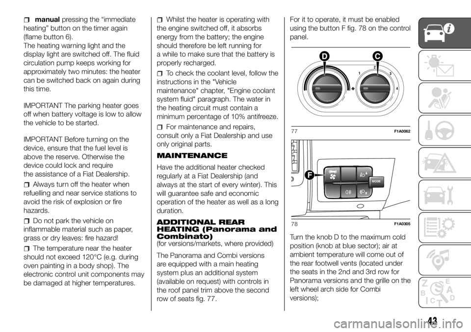
row of seats fig. 77.For it to operate, it must be enabled
using the button F fig. 78 on the control
panel.
Turn the knob D to the maximum cold
position (knob at blue sector); air at
ambient temperature will come out of
the rear footwell vents (located under
the seats in the 2nd and 3rd row for
Panorama versions and the grille on the
left wheel arch side for Combi
versions);77F1A0062
MODEF
78F1A0305
43
Page 49 of 304
WARNING
40)All adjustments must only be carried
out with the vehicle stationary and the
engine off. Head restraints must be
adjusted so that the head, rather than the
neck, rests on them. Only in this case
can they protect your head correctly. To
take best advantage of the protection
provided by the head restraint, adjust the
seat back so that you are sitting up straight
and your head is as close to the head
restraint as possible.
INTERIOR FITTINGS
COMPARTMENT
BENEATH PASSENGER
SIDE FRONT SEAT
Proceed as follows to use the
compartment:
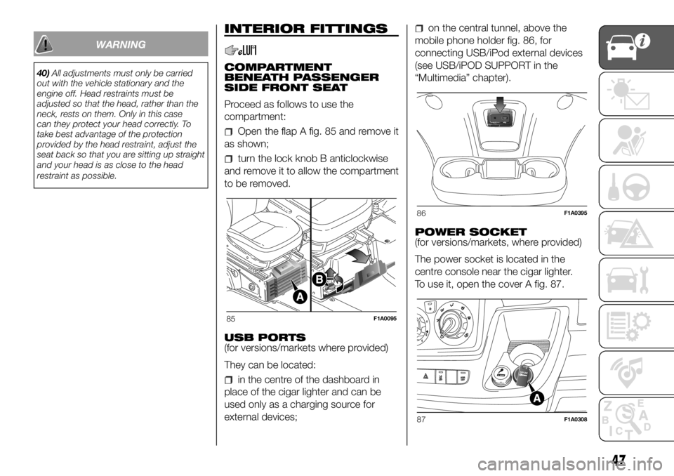
Open the flap A fig. 85 and remove it
as shown;
turn the lock knob B anticlockwise
and remove it to allow the compartment
to be removed.
USB PORTS
(for versions/markets where provided)
They can be located:
in the centre of the dashboard in
place of the cigar lighter and can be
used only as a charging source for
external devices;
on the central tunnel, above the
mobile phone holder fig. 86, for
connecting USB/iPod external devices
(see USB/iPOD SUPPORT in the
“Multimedia” chapter).
POWER SOCKET
(for versions/markets, where provided)
The power socket is located in the
centre console near the cigar lighter.
To use it, open the cover A fig. 87.
85F1A0095
86F1A0395
87F1A0308
47
Page 50 of 304
TABLET HOLDER
(for versions/markets, where provided)
It is located in the centre of the
dashboard and is designed to anchor a
tablet.
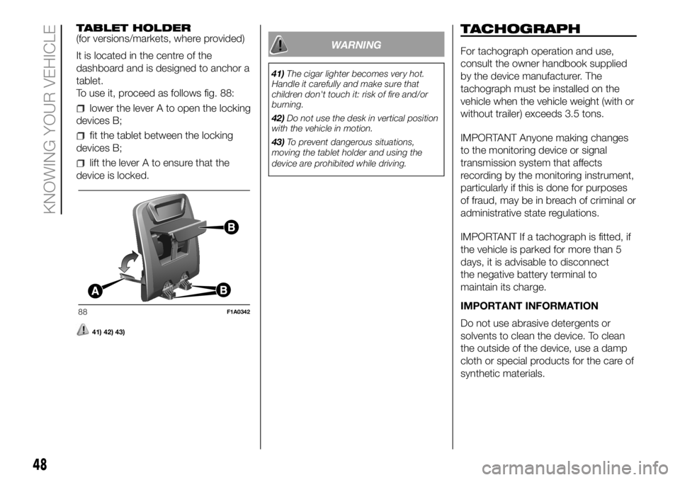
To use it, proceed as follows fig. 88:
lower the lever A to open the locking
devices B;
fit the tablet between the locking
devices B;
lift the lever A to ensure that the
device is locked.
41) 42) 43)
WARNING
41)The cigar lighter becomes very hot.
Handle it carefully and make sure that
children don't touch it: risk of fire and/or
burning.
42)Do not use the desk in vertical position
with the vehicle in motion.
43)To prevent dangerous situations,
moving the tablet holder and using the
device are prohibited while driving.
TACHOGRAPH
For tachograph operation and use,
consult the owner handbook supplied
by the device manufacturer. The
tachograph must be installed on the
vehicle when the vehicle weight (with or
without trailer) exceeds 3.5 tons.
IMPORTANT Anyone making changes
to the monitoring device or signal
transmission system that affects
recording by the monitoring instrument,
particularly if this is done for purposes
of fraud, may be in breach of criminal or
administrative state regulations.
IMPORTANT If a tachograph is fitted, if
the vehicle is parked for more than 5
days, it is advisable to disconnect
the negative battery terminal to
maintain its charge.
IMPORTANT INFORMATION
Do not use abrasive detergents or
solvents to clean the device. To clean
the outside of the device, use a damp
cloth or special products for the care of
synthetic materials.
88F1A0342
48
KNOWING YOUR VEHICLE
Page 53 of 304
KNOWING THE INSTRUMENT PANEL
This section of the booklet gives you all
the information you need to
understand, interpret and use the
instrument panel correctly.CONTROL PANEL AND
ON-BOARD INSTRUMENTS ........... 52
DISPLAY ........................................ 56
TRIP COMPUTER ........................... 58
WARNING LIGHTS AND
MESSAGES .................................... 60
-LOW BRAKE FLUID/HANDBRAKE
ENGAGED........................................... 60
-EBD FAILURE .................................... 61
-AIR BAG FAILURE .............................. 61
-SEAT BELTS REMINDER.................... 62
-ENGINE COOLANT TEMPERATURE
TOO HIGH........................................... 63
-LOW BATTERY CHARGE ................... 63
-LOW ENGINE OIL PRESSURE ........... 64
-ENGINE OIL DETERIORATED ............ 64
-INCOMPLETE DOOR/LOAD
COMPARTMENT CLOSURE................ 65
-POWER STEERING FAILURE ............. 65
-SELF-LEVELLING SUSPENSION
FAILURE .............................................. 65
-INJECTION/EOBD SYSTEM
FAILURE .............................................. 67
-UREA INJECTION SYSTEM FAILURE. 68
-ABS FAILURE..................................... 68
-FUEL RESERVE ................................. 68
-GLOW PLUG PREHEATING / GLOW
PLUG PREHEATING FAILURE ............. 69
-LOW DIESEL EMISSIONS ADDITIVE
(UREA) LEVEL WARNING .................... 69
-VEHICLE PROTECTION SYSTEM
FAILURE - FIAT CODE ......................... 70
-REAR FOG LIGHTS............................ 70
-GENERAL FAILURE INDICATION ....... 71
-DPF (PARTICULATE FILTER)
CLEANING UNDERWAY ...................... 72
-BRAKE PAD WEAR ............................ 72
-DRIVING ADVISOR ............................ 73-TPMS SYSTEM .................................. 74
-DIPPED BEAM HEADLIGHTS ............ 75
-FOLLOW ME HOME .......................... 75
-LEFT DIRECTION INDICATOR ............ 75
-RIGHT DIRECTION INDICATOR ......... 75
-FOG LIGHTS ...................................... 75
-CRUISE CONTROL ............................ 76
-SPEED LIMITER ................................. 76
-AUTOMATIC MAIN BEAM
HEADLIGHTS ...................................... 76
-MAIN BEAM HEADLIGHTS ................ 76
-"UP" FUNCTION ................................ 77
-EXTERIOR LIGHTS FAILURE .............. 78
-LOW ENGINE OIL PRESSURE
WARNING LIGHT FAILURE ................. 78
-BRAKE LIGHT FAILURE ..................... 78
-MAIN BEAM AUTOMATISM FAULT .... 78
-POSSIBLE ICE ON ROAD .................. 79
-SPEED LIMIT EXCEEDED .................. 79
-SCHEDULED SERVICING .................. 79
-FUEL CUT-OFF DEVICE INERTIA
SWITCH TRIPPED ............................... 80
-COMFORT-MATIC SYSTEM FAILURE
INDICATION ........................................ 80
-PARKING SENSOR FAILURE ............. 80
-DRIVING ADVISOR SYSTEM
FAILURE .............................................. 80
-TRAFFIC SIGN RECOGNITION
FAILURE .............................................. 80
-LIMITED RANGE ................................ 80
-START&STOP SYSTEM
ACTIVATION/DEACTIVATION............... 81
-START&STOP FAILURE ..................... 81
-LOW DIESEL EMISSIONS ADDITIVE
(UREA) LEVEL WARNING .................... 82
-WATER IN DIESEL FILTER (Diesel
versions) .............................................. 82
51
Page 54 of 304
CONTROL PANEL AND ON-BOARD INSTRUMENTS
.
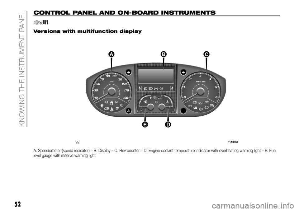
Versions with multifunction display
A. Speedometer (speed indicator) – B. Display – C. Rev counter – D. Engine coolant temperature indicator with overheating warning light – E. Fuel
level gauge with reserve warning light
92F1A0356
52
KNOWING THE INSTRUMENT PANEL
Page 55 of 304
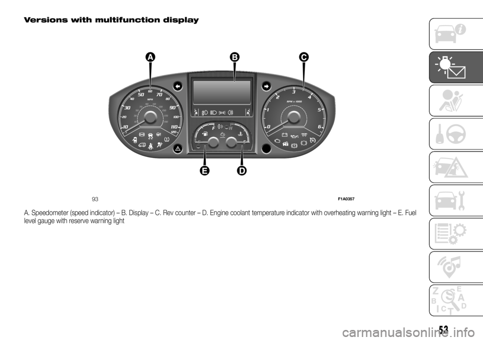
Versions with multifunction display
A. Speedometer (speed indicator) – B. Display – C. Rev counter – D. Engine coolant temperature indicator with overheating warning light – E. Fuel
level gauge with reserve warning light
93F1A0357
53
Page 56 of 304
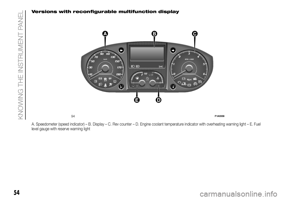
Versions with reconfigurable multifunction display
A. Speedometer (speed indicator) – B. Display – C. Rev counter – D. Engine coolant temperature indicator with overheating warning light – E. Fuel
level gauge with reserve warning light
94F1A0358
54
KNOWING THE INSTRUMENT PANEL
Page 57 of 304
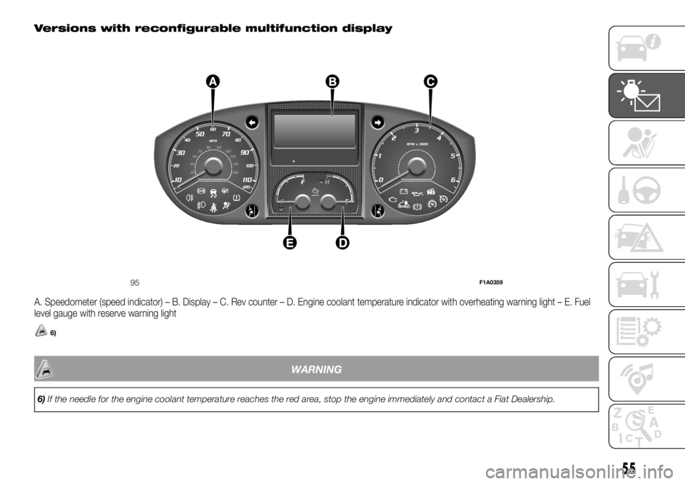
Versions with reconfigurable multifunction display
A. Speedometer (speed indicator) – B. Display – C. Rev counter – D. Engine coolant temperature indicator with overheating warning light – E. Fuel
level gauge with reserve warning light
6)
WARNING
6)If the needle for the engine coolant temperature reaches the red area, stop the engine immediately and contact a Fiat Dealership.
95F1A0359
55
Page 58 of 304
DISPLAY
(for versions/markets, where provided)
The vehicle may be equipped with a
multifunction display or with a
reconfigurable multifunction display,
able to display information that is useful
and necessary when driving.
MULTIFUNCTION
DISPLAY "STANDARD"
SCREEN
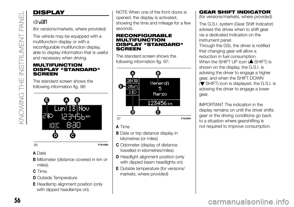
The standard screen shows the
following information fig. 96:
ADate
BMilometer (distance covered in km or
miles).
CTime.
DOutside Temperature
EHeadlamp alignment position (only
with dipped headlamps on).NOTE When one of the front doors is
opened, the display is activated,
showing the time and mileage for a few
seconds.
RECONFIGURABLE
MULTIFUNCTION
DISPLAY "STANDARD"
SCREEN
The standard screen shows the
following information fig. 97:
ATime
BDate or trip distance display in
kilometres (or miles)
COdometer (display of distance
travelled in kilometres/miles)
DHeadlight alignment position (only
with dipped beam headlights on)
EOutside temperature (for versions/
markets, where provided)GEAR SHIFT INDICATOR
(for versions/markets, where provided)
The G.S.I. system (Gear Shift Indicator)
advises the drives when to shift gear
via a dedicated indication on the
instrument panel.
Through the GSI, the driver is notified
that changing gear will allow a
reduction in fuel consumption.
When the SHIFT UP icon (
SHIFT) is
shown on the display, the G.S.I. is
advising the driver to engage a higher
gear, and when the SHIFT DOWN
(
SHIFT) icon is displayed, the G.S.I. is
advising the driver to engage a lower
gear.
IMPORTANT The indication in the
display remains on until the driver shifts
gear or the driving conditions go back
to a situation where gearshifting is
not required to improve consumption.
96F1A1040
97F1A1041
56
KNOWING THE INSTRUMENT PANEL