Up function FIAT DUCATO 2018 Owner handbook (in English)
[x] Cancel search | Manufacturer: FIAT, Model Year: 2018, Model line: DUCATO, Model: FIAT DUCATO 2018Pages: 304, PDF Size: 14.93 MB
Page 129 of 304
by pressing the brake pedal or
operating the handbrake;
by pressing the clutch pedal;
requesting a gear shift with an
automatic transmission in sequential
mode;
with the vehicle speed below the set
limit
by pressing the accelerator pedal; in
this case the system is not actually
turned off but the acceleration request
takes priority; the Cruise Control
remains activated, without the need to
press the CANC/RES button to restore
the previous conditions once the
acceleration is over.
The device is automatically switched off
in the following cases:
if the ABS or ESC systems
intervene;
in the event of system failure.
121) 122)
SPEED LIMITER
This device allows the vehicle speed to
be limited to a value set by the driver.
The maximum speed can be set both
with vehicle stationary and in motion.
The minimum speed that can be set is
30 km/h.When the device is active, the vehicle
speed depends on the accelerator
pedal, until the programmed speed limit
is reached (see "Speed limit
programming" paragraph).
If necessary (in the event of overtaking
for example), the set speed limit can
be exceeded by fully depressing the
accelerator pedal.
By gradually reducing the pressure on
the accelerator pedal, the function
will be reactivated as soon as the
vehicle speed drops below the
programmed speed.
Turning the device on
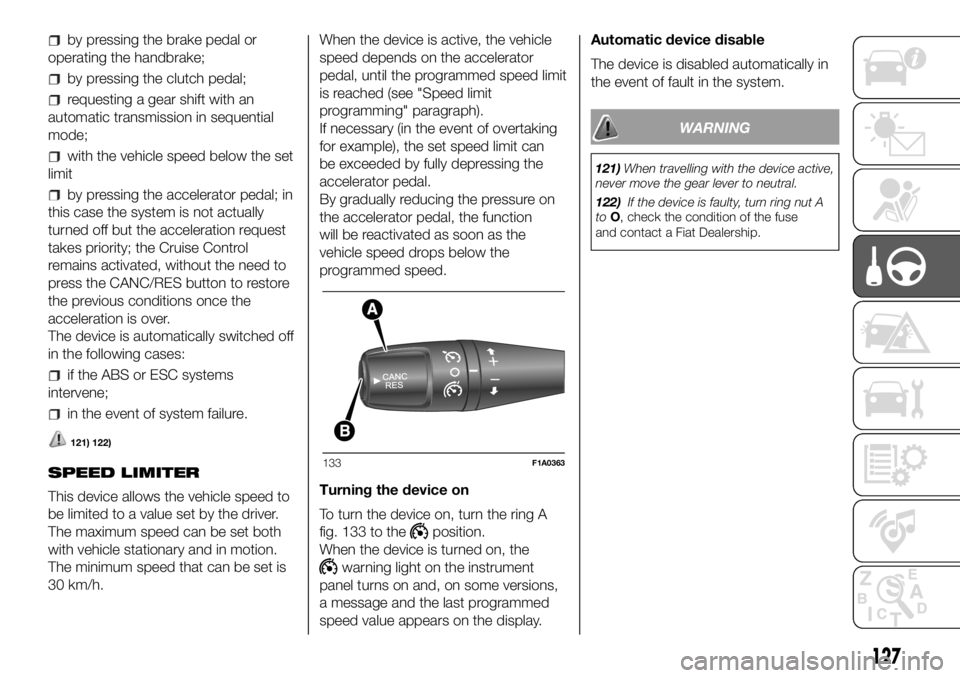
To turn the device on, turn the ring A
fig. 133 to the
position.
When the device is turned on, the
warning light on the instrument
panel turns on and, on some versions,
a message and the last programmed
speed value appears on the display.Automatic device disable
The device is disabled automatically in
the event of fault in the system.
WARNING
121)When travelling with the device active,
never move the gear lever to neutral.
122)If the device is faulty, turn ring nut A
toO, check the condition of the fuse
and contact a Fiat Dealership.
133F1A0363
127
Page 130 of 304
SPEED BLOCK
(for versions/markets, where provided)
The vehicle is equipped with a speed
limitation function that can be set at the
user's request to one of 4 predefined
values: 90, 100, 110, 130 km/h.
To activate/deactivate this function,
contact a Fiat Dealership.
Following the operation, a sticker will be
applied to the windscreen showing the
maximum speed setting.
IMPORTANT The speedometer could
indicate a higher maximum speed than
the effective one, set by the Dealership,
in accordance with the regulations in
force.
PARKING SENSORS
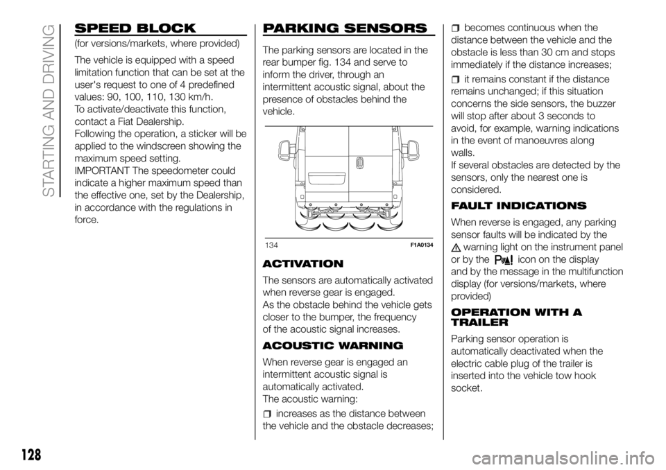
The parking sensors are located in the
rear bumper fig. 134 and serve to
inform the driver, through an
intermittent acoustic signal, about the
presence of obstacles behind the
vehicle.
ACTIVATION
The sensors are automatically activated
when reverse gear is engaged.
As the obstacle behind the vehicle gets
closer to the bumper, the frequency
of the acoustic signal increases.
ACOUSTIC WARNING
When reverse gear is engaged an
intermittent acoustic signal is
automatically activated.
The acoustic warning:
increases as the distance between
the vehicle and the obstacle decreases;
becomes continuous when the
distance between the vehicle and the
obstacle is less than 30 cm and stops
immediately if the distance increases;
it remains constant if the distance
remains unchanged; if this situation
concerns the side sensors, the buzzer
will stop after about 3 seconds to
avoid, for example, warning indications
in the event of manoeuvres along
walls.
If several obstacles are detected by the
sensors, only the nearest one is
considered.
FAULT INDICATIONS
When reverse is engaged, any parking
sensor faults will be indicated by the
warning light on the instrument panel
or by the
icon on the display
and by the message in the multifunction
display (for versions/markets, where
provided)
OPERATION WITH A
TRAILER
Parking sensor operation is
automatically deactivated when the
electric cable plug of the trailer is
inserted into the vehicle tow hook
socket.
134F1A0134
128
STARTING AND DRIVING
Page 136 of 304
Topping for additive Diesel
Emissions AdBlue (UREA)
When refuelling the additive for Diesel
Emissions AdBlue (UREA) with
dispensing gun:
park the vehicle on ground level;
turn off the engine by turning the key
in the OFF position;
open the fuel flap A fig. 137 and
then unscrew and remove the cap C
fig. 137 from the UREA filler;
insert the dispensing gun for topping
up UREA in the filler neck;
immediately stop filling the tank
UREA if it shows one of the cases listed
below:
- if AdBlue is spilled out of the filler
neck, clean up well the area and
proceed to filling up again;
- if during filling the dispensing gun
clicks, it indicates that the UREA tank is
full. Do not proceed with the
replacement, to prevent spillage of
AdBlue (UREA).
When you have finished topping up,
refit the cap C fig. 137 on the UREA
filler by turning it clockwise until it is fully
tightened;
turn the key in the pawl starter in the
ON position (no need to start the
engine);
wait for the warning on the
instrument panel to switch off before
moving the vehicle, the warning light
may stay on for a few seconds to half a
minute. In case of motor start-up and
movement of the vehicle, the warning
light will remain on for a longer period of
time, but there are no problems on the
engine functionality. If topping up is
done with the UREA tank empty, you
have to wait two minutes before
starting the vehicle.
When refuelling the additive for
Diesel Emissions AdBlue (UREA)
with bottle:
park the vehicle on ground level;
turn off the engine by turning the key
in the OFF position;
open the fuel flap A fig. 137 and
then unscrew and remove the cap C
fig. 137 from the UREA filler;
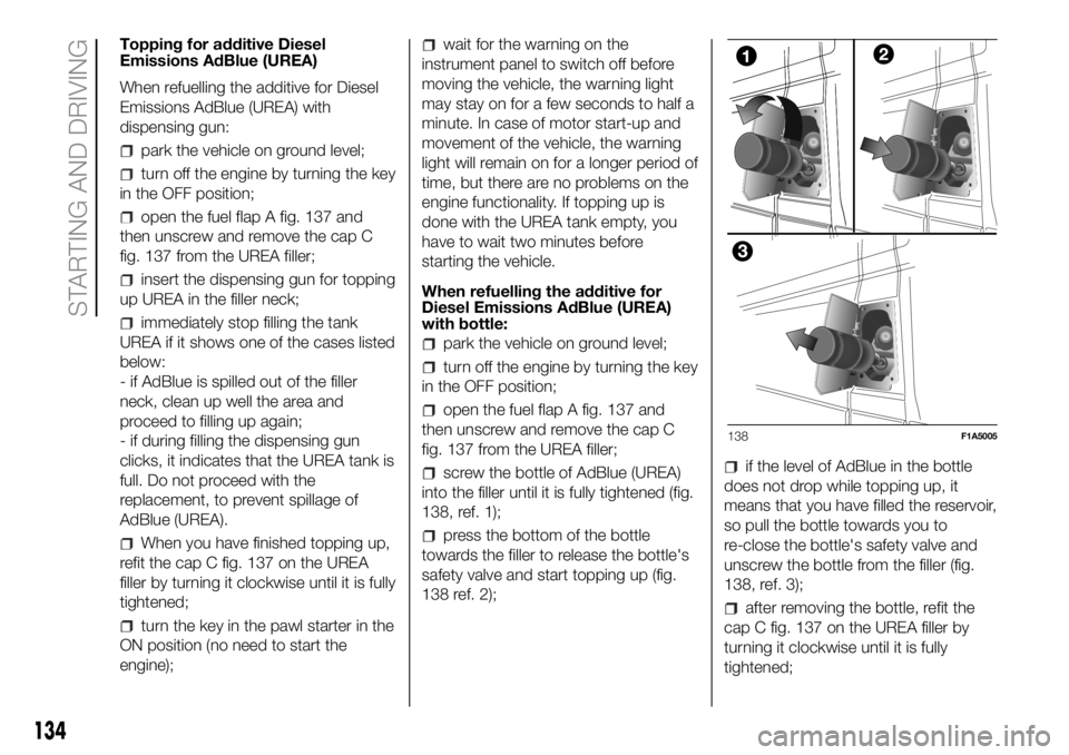
screw the bottle of AdBlue (UREA)
into the filler until it is fully tightened (fig.
138, ref. 1);
press the bottom of the bottle
towards the filler to release the bottle's
safety valve and start topping up (fig.
138 ref. 2);
if the level of AdBlue in the bottle
does not drop while topping up, it
means that you have filled the reservoir,
so pull the bottle towards you to
re-close the bottle's safety valve and
unscrew the bottle from the filler (fig.
138, ref. 3);
after removing the bottle, refit the
cap C fig. 137 on the UREA filler by
turning it clockwise until it is fully
tightened;
138F1A5005
134
STARTING AND DRIVING
Page 137 of 304
turn the key in the pawl starter in the
ON position (no need to start the
engine);
wait for the warning on the
instrument panel to switch off before
moving the vehicle, the warning light
may stay on for a few seconds to half a
minute. In case of motor start-up and
movement of the vehicle, the warning
light will remain on for a longer period of
time, but there are no problems on the
engine functionality;
if topping up is done with the UREA
tank empty, you have to wait two
minutes before starting the vehicle;
NOTE The driving conditions (altitude,
vehicle speed, load, etc.) determine the
quantity of UREA used by the vehicle.
In order to use the additive for Diesel
Emissions (UREA) correctly, see "Fluids
and lubricants" in the "Technical data".
132)
IMPORTANT
Exceeding the maximum filling level
of the tank UREA, it can cause damage
to the tank and spilling UREA. Please
avoid topping up after filling the tank.
DO NOT EXCEED THE MAXIMUM
LEVEL. The UREA freezes at under -11
° C. Although the system is designed
to operate below the freezing point
of the UREA, it is advisable not to fill the
tank beyond the maximum level
because if the UREA freezes the
system can be damaged.
If the UREA is spilled on painted
surfaces or aluminium, immediately
clean the area with water and use
absorbent material to collect the fluid
that has been spilled on the ground.
Do not try to start the engine if
UREA was accidentally added to the
Diesel fuel tank, this can result in
serious engine damage, contact
Dealership.
Use AdBlue only according to DIN
70 070 and ISO 22241-1. Other fluids
may cause damage to the system: also
exhaust emissions would no longer
comply with the law. The distribution
companies are responsible for the
compliance of their product. Observe
the precautions of storage and
servicing, in order to preserve the initial
qualities. The manufacturer of the
vehicle does not recognise any
guarantee in case of malfunctions and
damage caused to the vehicle due
to the use of urea (AdBlue) not in
accordance with regulations.
Any introduction of diesel fuel inside
the tank AdBlue, causes irreversible
damage to the pumping unit circuit
AdBlue.
Do not add additives to AdBlue. Do
not dilute AdBlue with tap water as
this may damage the system of
purification of exhaust gases.
In case of damage to the sewage
system of exhaust gas resulting from
the use of additives / tap water, the
introduction of diesel fuel, or at least by
not fulfilling the requirements, the
warranty expires.
AdBlue tank topping (UREA) in cold
environments
Since AdBlue (UREA) starts to freeze
around the -11 °C, the vehicle is
equipped with an automatic system of
heating UREA that allows the system to
function properly at temperatures
below -11 °C.
If the vehicle remains idle for a long
period at temperatures below the -11
°C, the UREA in the tank might freeze.
If the tank UREA was filled beyond
the maximum level and freezes, it can
be damaged; for this reason it is
advisable not to exceed the maximum
level of the tank.
Pay extra attention to avoid exceeding
the maximum level when you use
portable containers for topping up.
135
Page 141 of 304
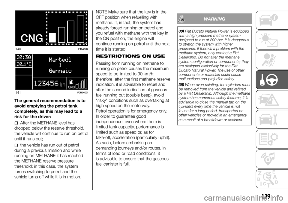
The general recommendation is to
avoid emptying the petrol tank
completely, as this may lead to a
risk for the driver:
After the METHANE level has
dropped below the reserve threshold,
the vehicle will continue to run on petrol
until it runs out;
the vehicle has run out of petrol
during a previous mission and while
running on METHANE it has reached
the METHANE reserve pressure
threshold: in this case, the system
forces switching to petrol and the
vehicle turns off while it is in motion.NOTE Make sure that the key is in the
OFF position when refuelling with
methane. If, in fact, the system has
already forced running on petrol and
you refuel with methane with the key in
the ON position, the engine will
continue running on petrol until the next
time it is started.
RESTRICTIONS ON USE
Passing from running on methane to
running on petrol causes the maximum
speed to be limited to 90 km/h;
therefore, after the first methane reserve
indication, it is advisable to refuel and
after the second indication of gaseous
fuel running out (double beep), avoid
"risky" conditions such as overtaking at
high speed on the motorway.
Petrol operation is for emergency only.
In order to guarantee good
independence, even where there is
limited tank capacity, performance is
limited such as speed or, as for
take-off, acceleration (particularly uphill).
As such, before embarking on
demanding journeys and/or routes, in
terms of load or road conditions, it
is advisable to ensure that the gaseous
fuel canister is full.
WARNING
38)Fiat Ducato Natural Power is equipped
with a high pressure methane system
designed to run at 200 bar. It is dangerous
to stretch the system with higher
pressures. If there is a problem with the
methane system, only contact a Fiat
Dealership. Do not alter the methane
system configuration or components; they
are designed exclusively for the Fiat
Ducato Natural Power. The use of other
components or materials could cause
malfunctions and prejudice safety.
39)When oven painting, the cylinders must
be removed from the vehicle and refitted
by a Fiat Dealership. Although the methane
system has numerous safety features, it is
advisable to close the manual tap on the
cylinders every time the vehicle is not
in use for a long period, transported on
other vehicles or moved in an emergency
as a result of a breakdown or accident.
140F1A0436
141F0N0403I
139
Page 143 of 304
TOWING TRAILERS
IMPORTANT NOTES
The vehicle must be provided with a
type-approved tow hook and adequate
electrical system to tow caravans or
trailers. Installation should be carried
out by specialised personnel who
will issue the required papers for
travelling on roads.
Install any specific and/or additional
door mirrors as specified by the
Highway Code.
Remember that when towing a trailer,
steep hills are harder to climb, the
braking spaces increase and overtaking
takes longer depending on the overall
weight.
Engage a low gear when driving
downhill, rather than constantly using
the brake.
The weight of the trailer on the vehicle
tow hook will reduce the loading
capacity of the vehicle by the same
amount. Consider the weight of the
trailer fully laden, including accessories
and luggage, to make sure you do
not exceed the maximum towable
weight (shown on the vehicle
registration document).Do not exceed the speed limits specific
to each country you are driving in, in
the case of vehicles towing trailers.
In any case, the top speed must not
exceed 100 km/h.
You are advised to fit a suitable
stabiliser to the trailer drawbar.
In the vehicles equipped with parking
sensors, after fitting the tow hook
malfunctioning warnings may be
displayed, as some parts (tow bar, ball
tow hook) may be within the sensor
detection range. In this case the
detection range must be adjusted or
the parking assistance function must be
deactivated.
In vehicles equipped with "Comfort-
matic" transmission, make sure that the
gearbox is in neutral (N) (checking that
the vehicle moves when pushed) and
proceed in the same way as for towing
a normal vehicle with manual
transmission. If the gearbox cannot be
put in neutral, do not tow the vehicle
and contact a Fiat Dealership.
137) 138)
INSTALLING THE TOW
HOOK
The towing device should be fastened
to the body by specialised technicians
according to any additional and/or
integrative information supplied by the
Manufacturer of the device.
The towing device must meet current
regulations with reference to Directive
94/20/EC and subsequent
amendments.
For any version the towing device used
must match the towable weight of the
vehicle on which it is to be installed.
For the electric connection a standard
connector should be used which is
generally placed on a special bracket
normally fastened to the towing device,
and a special ECU for external trailer
light control must be installed on the
vehicle. For the electrical connection, 7
or 13 pin 12 V DC connections are to
be used (CUNA/UNI and ISO/DIN
Standards). Follow the instructions
provided by the vehicle manufacturer
and/or the tow hitch manufacturer.
Any electric brake (or electric winch,
etc.) should be supplied directly by the
battery through a cable with a section
of at least 2.5 mm
2.
IMPORTANT Electric brakes or other
devices must be used with engine
running.
141
Page 149 of 304
PROLONGED
VEHICLE INACTIVITY
If the vehicle needs to be off the road
for longer than one month, the following
precautions must be taken:
park the vehicle indoors in a dry
and, if possible, well-ventilated place;
engage a gear;
check that the handbrake is not
engaged;
disconnect the negative battery
terminal; if the vehicle is equipped with
a battery disconnection function
(disconnector), see the description of
the procedure in the "Controls"
paragraph in the "Dashboard and
controls" section;
clean and protect the painted parts
using protective wax;
clean and protect the shiny metal
parts using special compounds
available commercially;
sprinkle talcum powder on the
windscreen and rear window wiper
rubber blades and lift them off the
glass;
slightly open the windows;
cover the vehicle with a piece of
fabric or perforated plastic sheet. Do
not use compact plastic tarpaulins,
which prevent humidity from
evaporating from the surface of the
vehicle;
inflate tyres to +0.5 bar above the
standard specified pressure and check
it at intervals;
do not drain the engine cooling
system.
IMPORTANT If the vehicle is equipped
with an alarm system, switch off the
vehicle alarm with the remote control.
IMPORTANT After turning the ignition
key to STOP and having closed the
driver side door, wait at least one
minute before disconnecting the
electrical supply from the battery. When
reconnecting the electrical supply to
the battery, make sure that the ignition
key is in the STOP position and the
driver side door is closed.
147
Page 151 of 304
REPLACING A BULB
GENERAL
INSTRUCTIONS
140) 141)
47)
When a light is not working, check
that the corresponding fuse is intact
before changing a bulb. For the location
of fuses, refer to the paragraph
"Replacing fuses" in this chapter.
before changing a bulb check the
contacts for oxidation;
burnt bulbs must be replaced by
others of the same type and power;
always check the headlight beam
direction after changing a bulb;
IMPORTANT A slight misting may
appear on the internal surface of the
headlight: this does not indicate a fault
and is caused by low temperature
and the degree of humidity in the air.
Misting will rapidly disappear when the
headlights are switched on. The
presence of drops inside the headlights
indicates infiltration of water. Contact
a Fiat Dealership.
WARNING
140)Modifications or repairs to the
electric system that are not carried out
properly or do not take the system
technical specifications into account can
cause malfunctions leading to the risk
of fire.
141)Halogen bulbs contain pressurised
gas, in the case of breakage they may
burst causing glass fragments to be
projected outwards.
WARNING
47)Halogen bulbs must be handled
holding the metallic part only. Touching the
transparent part of the bulb with your
fingers may reduce the intensity of the
emitted light and even reduce the lifespan
of the bulb. In the event of accidental
contact, wipe the bulb with a cloth
moistened with alcohol and let the bulb
dry.
149
Page 176 of 304
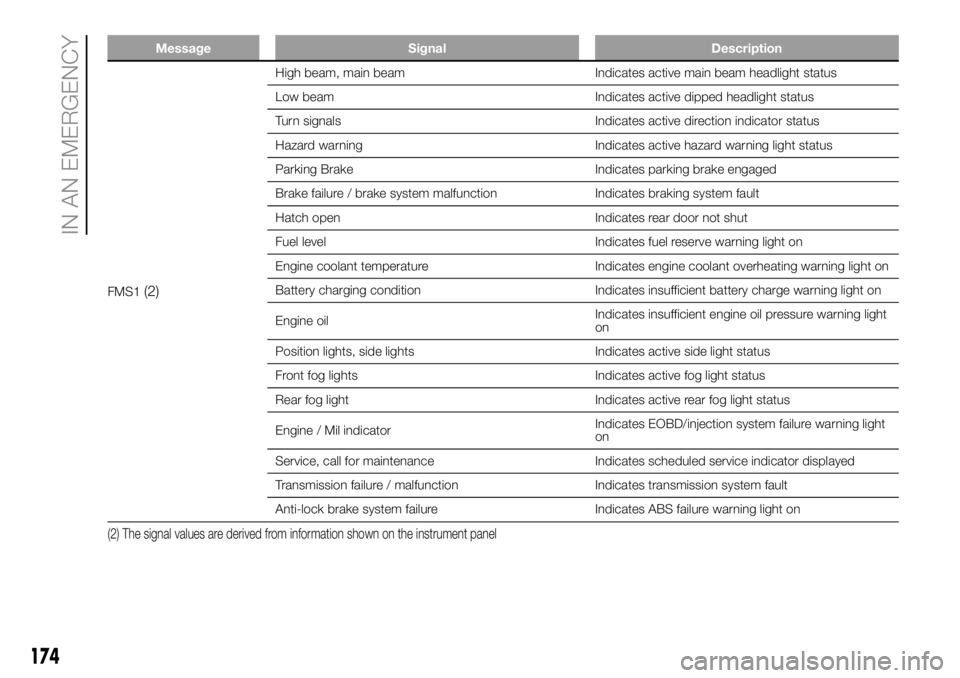
Message Signal Description
FMS1(2)
High beam, main beam Indicates active main beam headlight status
Low beam Indicates active dipped headlight status
Turn signals Indicates active direction indicator status
Hazard warning Indicates active hazard warning light status
Parking Brake Indicates parking brake engaged
Brake failure / brake system malfunction Indicates braking system fault
Hatch open Indicates rear door not shut
Fuel level Indicates fuel reserve warning light on
Engine coolant temperature Indicates engine coolant overheating warning light on
Battery charging condition Indicates insufficient battery charge warning light on
Engine oilIndicates insufficient engine oil pressure warning light
on
Position lights, side lights Indicates active side light status
Front fog lights Indicates active fog light status
Rear fog light Indicates active rear fog light status
Engine / Mil indicatorIndicates EOBD/injection system failure warning light
on
Service, call for maintenance Indicates scheduled service indicator displayed
Transmission failure / malfunction Indicates transmission system fault
Anti-lock brake system failure Indicates ABS failure warning light on
(2) The signal values are derived from information shown on the instrument panel
174
IN AN EMERGENCY
Page 177 of 304
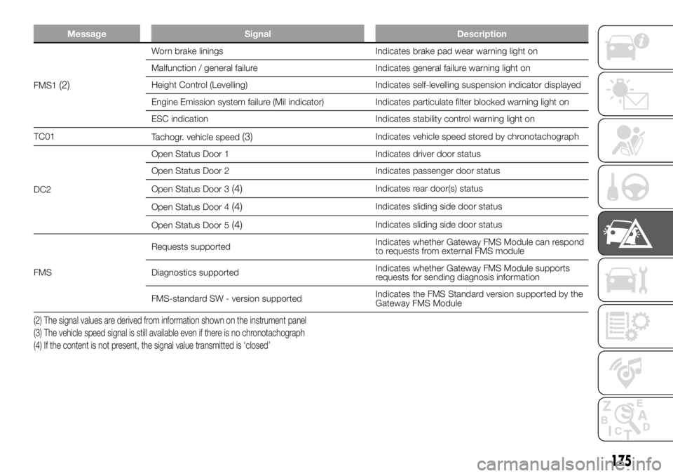
Message Signal Description
FMS1(2)
Worn brake linings Indicates brake pad wear warning light on
Malfunction / general failure Indicates general failure warning light on
Height Control (Levelling) Indicates self-levelling suspension indicator displayed
Engine Emission system failure (Mil indicator) Indicates particulate filter blocked warning light on
ESC indication Indicates stability control warning light on
TC01
Tachogr. vehicle speed
(3)Indicates vehicle speed stored by chronotachograph
DC2Open Status Door 1 Indicates driver door status
Open Status Door 2 Indicates passenger door status
Open Status Door 3
(4)Indicates rear door(s) status
Open Status Door 4
(4)Indicates sliding side door status
Open Status Door 5
(4)Indicates sliding side door status
FMSRequests supportedIndicates whether Gateway FMS Module can respond
to requests from external FMS module
Diagnostics supportedIndicates whether Gateway FMS Module supports
requests for sending diagnosis information
FMS-standard SW - version supportedIndicates the FMS Standard version supported by the
Gateway FMS Module
(2) The signal values are derived from information shown on the instrument panel
(3) The vehicle speed signal is still available even if there is no chronotachograph
(4) If the content is not present, the signal value transmitted is ‘closed’
175