turn signal FIAT DUCATO 244 2002 3.G Connect NavPlus Manual
[x] Cancel search | Manufacturer: FIAT, Model Year: 2002, Model line: DUCATO 244, Model: FIAT DUCATO 244 2002 3.GPages: 246, PDF Size: 3.39 MB
Page 183 of 246
CONNECT Nav+
182
To turn the Autostore function on
(automatic station storage) press the
knob 22-fig. 1after selecting it.
When this function is on, the radio
automatically stores the stations with
the strongest signal, in decreasing or-
der of intensity of the signal in the fre-
quency band tuned:
– 6 stations in the FM1, FM2 or FM3
band or
– 6 stations in the MW band or
– 6 stations in the LW band.
If the TA function is on (traffic infor-
mation), only stations that broadcast
traffic information will be stored. This
function can be turned on also when
playing a CD.
During automatic storage the display
shows the wording “Autostore”. To
interrupt the automatic storage
process, turn off the “Autostore”
function pressing the “ESC” key 23-
fig. 1; the radio will tune the station
heard before the function was acti-
vated. On the preset keys 1 ÷ 6-fig. 1the
stations that have a strong signal in
that moment will be stored, in the pre-
set band. After storage the radio tunes
automatically to the first station of the
FM1 band, corresponding to the fre-
quency stored on preset key 1-fig. 1.
Every station is stored only once, ex-
cept in the case of regional pro-
grammes which in certain cases might
be stored twice.
The behaviour of the set during Au-
tostore is as follows:
– at the beginning of the Autostore
function all the other functions are dis-
abled
– any change in volume is not shown
on the display– pressing one of the preset keys 1÷
6-fig. 1the automatic storage process
is interrupted and the station stored
with that key is tuned
– selecting and activating a radio
function (e.g. PTY) the automatic stor-
age process is interrupted, the last sta-
tion heard before tuning on Autostore
is tuned and the function associated
with the key pressed is run
– selecting and activating one or both
TA/AF functions during the automat-
ic storage process, automatic storage
will be interrupted, the TA (traffic in-
formation) and AF (alternative fre-
quencies) functions will be turned
on/off and a new automatic storage
process will be started
– changing the audio source (Radio,
CD) during the automatic storage
process, the Autostore function is not
interrupted.
IMPORTANTIt may occur that
the Autostore function is unable to
find 6 stations with a strong signal; in
this case only the stations found are
stored. “AUTOSTORE” FUNCTION (AUTOMATIC STATION STORAGE)
Page 184 of 246
CONNECT Nav+
183
“ST/MONO” FUNCTION
To turn on/off the Stereo function
(stereo station reception) press the
knob 22-fig. 1after selecting the
St/Mono function.
When stereo reception is on the dis-
play shows “STEREO”, when it is off
the display shows “MONO”.
When the signal of the station tuned
is weak, to improve the sound quality,
it is advisable to switch to “MONO”.CD MODE
To guarantee optimum playing, use
original CDs. If using R/RW CDs, use
top quality CDs duplicated at as low
as possible speed.
IMPORTANTNever use 8 mm
audio CDs, even with the specific
adapter, since this format will damage
the system.
Choosing the CD source with the
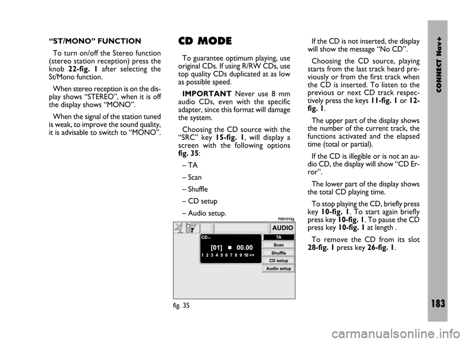
“SRC” key 15-fig. 1, will display a
screen with the following options
fig. 35:
– TA
– Scan
– Shuffle
– CD setup
– Audio setup.If the CD is not inserted, the display
will show the message “No CD”.
Choosing the CD source, playing
starts from the last track heard pre-
viously or from the first track when
the CD is inserted. To listen to the
previous or next CD track respec-
tively press the keys 11-fig. 1or 12-
fig. 1.
The upper part of the display shows
the number of the current track, the
functions activated and the elapsed
time (total or partial).
If the CD is illegible or is not an au-
dio CD, the display will show “CD Er-
ror”.
The lower part of the display shows
the total CD playing time.
To stop playing the CD, briefly press
key 10-fig. 1. To start again briefly
press key 10-fig. 1. To pause the CD
press key 10-fig. 1at length .
To remove the CD from its slot
28-fig. 1press key 26-fig. 1.
fig. 35
F0D1012g
Page 189 of 246
CONNECT Nav+
188
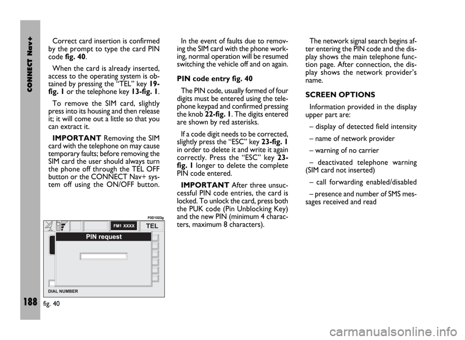
Correct card insertion is confirmed
by the prompt to type the card PIN
code fig. 40.
When the card is already inserted,
access to the operating system is ob-
tained by pressing the “TEL” key 19-
fig. 1or the telephone key 13-fig. 1.
To remove the SIM card, slightly
press into its housing and then release
it; it will come out a little so that you
can extract it.
IMPORTANTRemoving the SIM
card with the telephone on may cause
temporary faults; before removing the
SIM card the user should always turn
the phone off through the TEL OFF
button or the CONNECT Nav+ sys-
tem off using the ON/OFF button.In the event of faults due to remov-
ing the SIM card with the phone work-
ing, normal operation will be resumed
switching the vehicle off and on again.
PIN code entry fig. 40
The PIN code, usually formed of four
digits must be entered using the tele-
phone keypad and confirmed pressing
the knob 22-fig. 1. The digits entered
are shown by red asterisks.
If a code digit needs to be corrected,
slightly press the “ESC” key 23-fig. 1
in order to delete it and write it again
correctly. Press the “ESC” key 23-
fig. 1longer to delete the complete
PIN code entered.
IMPORTANTAfter three unsuc-
cessful PIN code entries, the card is
locked. To unlock the card, press both
the PUK code (Pin Unblocking Key)
and the new PIN (minimum 4 charac-
ters, maximum 8 characters).The network signal search begins af-
ter entering the PIN code and the dis-
play shows the main telephone func-
tion page. After connection, the dis-
play shows the network provider’s
name.
SCREEN OPTIONS
Information provided in the display
upper part are:
– display of detected field intensity
– name of network provider
– warning of no carrier
– deactivated telephone warning
(SIM card not inserted)
– call forwarding enabled/disabled
– presence and number of SMS mes-
sages received and read
fig. 40
F0D1023g
Page 195 of 246
CONNECT Nav+
194
“Messages” FUNCTION
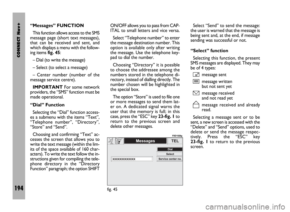
This function allows access to the SMS
message page (short text messages),
that can be received and sent, and
which displays a menu with the follow-
ing items fig. 45:
– Dial (to write the message)
– Select (to select a message)
– Center number (number of the
message service centre).
IMPORTANTFor some network
providers, the “SMS” function must be
made operational.
“Dial” Function
Selecting the “Dial” function access-
es a submenu with the items “Text”,
“Telephone number”, “Directory”,
“Store” and “Send”.
Choosing and confirming “Text” ac-
cesses the screen that allows you to
write the text message (within the lim-
its of the space available of 160 char-
acters). To write the text follow the in-
structions given for compiling the tele-
phone directory in the “Directory
Function” paragraph; the option SHIFTON/OFF allows you to pass from CAP-
ITAL to small letters and vice versa.
Select “Telephone number” to enter
the message destination number. This
option is available only after writing
the message. Use the telephone key-
pad to dial the number.
Choosing “Directory” it is possible
to choose the addressee among the
numbers stored in the telephone di-
rectory, instead of dialling directly. The
number chosen will be highlighted in
the special box.
The option “Store” is used to file one
or more messages to send them lat-
er on. A dedicated signal warns the
user that the memory is full; in this
case, press the “ESC” key 23-fig. 1to
return to the previous screen and
delete other messages.Select “Send” to send the message:
the user is warned that the message is
being sent and, at the end, if message
sending was successful or not.
“Select” function
Selecting this function, the present
SMS messages are displayed. They may
be of 4 types:
ímessage sent
îmessage written
but not sent yet
ómessage received
and not read yet
ñmessage received and already
read.
Selecting a message sent or to be
sent, a new screen is accessed with the
“Delete” and “Send” options, used to
delete or send the message respec-
tively. Press the “ESC” key
23-fig. 1to return to the previous
screen.
fig. 45
F0D1028g
Page 199 of 246
CONNECT Nav+
198
GENERAL
INFORMATION
The navigator integrated in the
CONNECT Nav+ allows you to reach
the chosen destination by visual and
voice instructions. Use of the naviga-
tion system is quick, convenient, safe
and above all very flexible because it al-
lows you to call up already pro-
grammed destinations or points of ref-
erence such as hotels, monuments,
public structures, fuel stations or Fi-
at Dealerships.
The vehicle position is determined
through the GPS system (Global Posi-
tioning System) installed on the vehicle.
The GPS system is fitted with an an-
tenna and a reception module inte-
grated in the telematic system. This sys-
tem configuration dynamically process-
es the satellite signals, those from the
right and left odometer, the reversing
signal and the information of the gyro-
scope integrated in the navigation com-
puter, integrating them with the cur-
rent position of the vehicle to obtain an
“estimated vehicle point”.The signals from the right and left
odometer make it possible to deter-
mine the movement of the vehicle, the
gyroscope signal identifies any turn-
ing and the reversing sensor distin-
guishes the direction of travel.
The Fiat navigation system helps the
driver while he/ahe drives by suggest-
ing vocally and graphically the opti-
mum routing to reach the preset des-
tination.IMPORTANT NOTES
– GPS reception is difficult under
trees, among tall buildings, in multi-lev-
el car parks, tunnels and everywhere
reception of the satellite antenna may
be hindered.
– The GPS system needs about 15
minutes for activation if the vehicle
battery is disconnected.
– The GPS system needs a few min-
utes to determine the new position of
the vehicle if it is turned off and the ve-
hicle is moved with the system off (e.g.:
by breakdown van).
– In the lack of satellite information,
the system uses information from the
gyroscope and from the special sen-
sors for temporary data analysis.
– The GPS satellite aerial must not
be covered with metal or damp ob-
jects.
N N
A A
V V
I I
G G
A A
T T
O O
R R
( (
N N
A A
V V
) )
The navigation system sug-
gestions do not exempt the
driver from full responsibility due to
his driving behaviour and to com-
pliance with road and other traffic
regulations. The responsibility for
road safety always and in any case
lies with the vehicle driver.
WARNING
Page 201 of 246
CONNECT Nav+
200
SCREEN OPTIONS
AND FUNCTIONS
The main information and functions
provided and managed by the naviga-
tion system are:
ëGPS signal symbol which differs in
colour depending on the quality of re-
ception;
– voice and visual instructions with
indications of distance from the des-
tination and planned arrival time;
– detailed map in different colours
and with different scales to clearly
show the vehicle position, route and
destination;
– customisation of the navigation sys-
tem with possibility of entering pre-
memorised destinations with street
and street number;
– automatic memorising of the last 8
destinations;
– name of current street;– possibility to choose the route ac-
cording to personal preference;
– information on current position;
– information on arrival time;
– system diagnostics and warnings
about possible disturbances.
If the system contains a wrong CD-
ROM, an audio CD or no CD, when-
ever the system asks for the navigation
CD-ROM for route calculation or map
up-date, the insertion prompt will ap-
pear on the display.
Navigation functions are mainly con-
trolled using the knob 22-fig. 1:
– rotate the knob to access the var-
ious map zoom levels;
– press the knob to display the first
menu page;
– use the knob to select and confirm
the “Other menu” item and access the
following menu pages;
– press the knob again and the menu
page will disappear.
GRAPHIC
INSTRUCTIONS
The main navigation function page
and the MAIN page display the ma-
noeuvres to be made using arrows or
symbols.
The downward arrow represents
next manoeuvre (turn left, right,
straight on, U-turn) while the upward
arrow or the symbol on top represent
the next one. The number displayed
under the arrow indicates the vehicle
distance from the turn point.
The small arrow down on the right-
hand side of the display (on the MAIN
page) or in the top box (on the main
navigation function page) indicates the
destination direction. Next to this ar-
row the planned arrival time and the
distance still to be covered are also in-
dicated.