key FIAT DUCATO 244 2005 3.G Owner's Manual
[x] Cancel search | Manufacturer: FIAT, Model Year: 2005, Model line: DUCATO 244, Model: FIAT DUCATO 244 2005 3.GPages: 258, PDF Size: 4.05 MB
Page 41 of 258
40GETTING TO KNOW YOUR VEHICLE
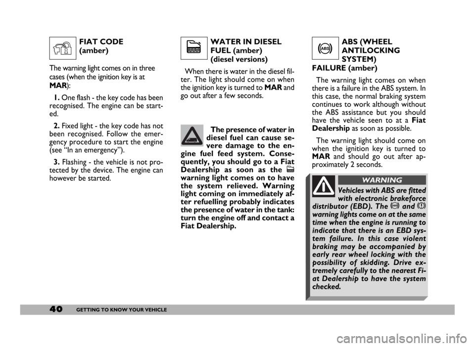
WATER IN DIESEL
FUEL (amber)
(diesel versions)
When there is water in the diesel fil-
ter. The light should come on when
the ignition key is turned to MAR and
go out after a few seconds.ABS (WHEEL
ANTILOCKING
SYSTEM)
FAILURE (amber)
The warning light comes on when
there is a failure in the ABS system. In
this case, the normal braking system
continues to work although without
the ABS assistance but you should
have the vehicle seen to at a Fiat
Dealershipas soon as possible.
The warning light should come on
when the ignition key is turned to
MARand should go out after ap-
proximately 2 seconds.
c
The presence of water in
diesel fuel can cause se-
vere damage to the en-
gine fuel feed system. Conse-
quently, you should go to a Fiat
Dealership as soon as the
c
warning light comes on to have
the system relieved. Warning
light coming on immediately af-
ter refuelling probably indicates
the presence of water in the tank:
turn the engine off and contact a
Fiat Dealership.
>
FIAT CODE
(amber)
The warning light comes on in three
cases (when the ignition key is at
MAR):
1.One flash - the key code has been
recognised. The engine can be start-
ed.
2.Fixed light - the key code has not
been recognised. Follow the emer-
gency procedure to start the engine
(see “In an emergency”).
3. Flashing - the vehicle is not pro-
tected by the device. The engine can
however be started.
Y
Vehicles with ABS are fitted
with electronic brakeforce
distributor (EBD). The >and x
warning lights come on at the same
time when the engine is running to
indicate that there is an EBD sys-
tem failure. In this case violent
braking may be accompanied by
early rear wheel locking with the
possibility of skidding. Drive ex-
tremely carefully to the nearest Fi-
at Dealership to have the system
checked.
WARNING
Page 42 of 258
41GETTING TO KNOW YOUR VEHICLE
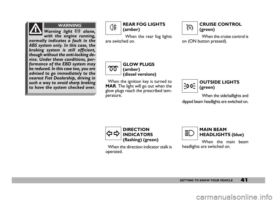
CRUISE CONTROL
(green)
When the cruise control is
on (ON button pressed).
GLOW PLUGS
(amber)
(diesel versions)
When the ignition key is turned to
MAR. The light will go out when the
glow plugs reach the prescribed tem-
perature.
DIRECTION
INDICATORS
(flashing) (green)
When the direction indicator stalk is
operated.OUTSIDE LIGHTS
(green)
When the side/taillights and
dipped beam headlights are switched on.
MAIN BEAM
HEADLIGHTS (blue)
When the main beam
headlights are switched on.
m
y
3
1
REAR FOG LIGHTS
(amber)
When the rear fog lights
are switched on.
4ÜWarning light >alone,
with the engine running,
normally indicates a fault in the
ABS system only. In this case, the
braking system is still efficient,
though without the anti-locking de-
vice. Under these conditions, per-
formance of the EBD system may
be reduced. In this case too, you are
advised to go immediately to the
nearest Fiat Dealership, driving in
such a way to avoid sharp braking
to have the system checked over.
WARNING
Page 53 of 258
52GETTING TO KNOW YOUR VEHICLE
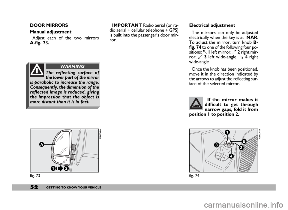
fig. 73
F0D0048m
fig. 74
F0D0041m
If the mirror makes it
difficult to get through
narrow gaps, fold it from
position 1 to position 2.
Electrical adjustment
The mirrors can only be adjusted
electrically when the key is at MAR.
To adjust the mirror, turn knob B-
fig. 74to one of the following four po-
sitions: Í1left mirror, È2right mir-
ror, Î3left wide-angle, Ï4right
wide-angle
Once the knob has been positioned,
move it in the direction indicated by
the arrows to adjust the reflecting sur-
face of the selected mirror.
The reflecting surface of
the lower part of the mirror
is parabolic to increase the range.
Consequently, the dimension of the
reflected image is reduced, giving
the impression that the object is
more distant than it is in fact.
WARNING
DOOR MIRRORS
Manual adjustment
Adjust each of the two mirrors
A-fig. 73.IMPORTANTRadio aerial (or ra-
dio aerial + cellular telephone + GPS)
is built into the passenger’s door mir-
ror.
Page 60 of 258
59GETTING TO KNOW YOUR VEHICLE
SELF-STANDING SUPPLEMENTARY
HEATER (where provided)
The vehicle can be equipped, upon re-
quest, with two different self-standing
heaters:one is totally automatic
whereas the other is programmable.
AUTOMATIC VERSION
The supplementary heater is totally in-
dependent from the engine.
This heater is switched on automat-
ically (if required) when turning the ig-
nition key to MAR. LOOKING AFTER THE
SYSTEM
During the winter, the climate con-
trol system must be turned on at least
once a month for about ten minutes.
Before summer, have the system
checked at a Fiat Dealership.PROGRAMMABLE VERSION
The supplementary heater is totally
independent from the engine and can
be used to:
– heat the passenger compartment
when the engine is off;
– defrost the windows;
– heat the engine coolant and con-
sequently the engine before starting.
The system consists of:
– a diesel burner to heat coolant with
exhaust fume muffler;
– a metering pump connected to the
vehicle fuel pipes to feed the burner;
– a heat exchanger connected to the
engine cooling system pipes; The system is filled with
R134a refrigerant which
will not pollute the envi-
ronment in the event of leakage.
Under no circumstances should
R12 fluid be used as it is incom-
patible with the system compo-
nents and contains CFC.
The heater burns fuel in the
same way as the engine,
though, of course, to a lesser degree
and therefore to avoid intoxication
and suffocation, never use the sup-
plementary heater in closed areas,
garages or workshops not equipped
with specific exhaust evacuation
devices even for short periods of
time.
WARNING
Page 66 of 258
65GETTING TO KNOW YOUR VEHICLE
STEERING COLUMN
STALKS
LEFT-HAND STALK
The left-hand stalk operates most of
the external lights.
The external lights can only be
switched on when the ignition key is
at MAR. The instrument panel and
the heating/ventilation (or climate con-
trol system) controls and the cigar
lighter ring will come on with the ex-
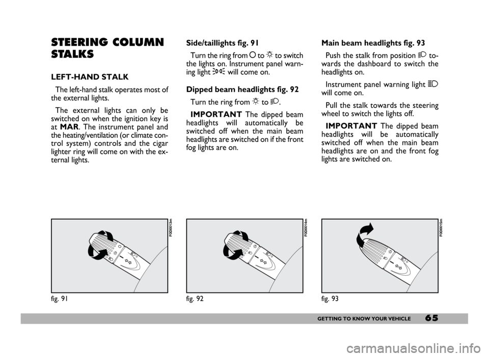
ternal lights.Side/taillights fig. 91
Turn the ring from åto 6to switch
the lights on. Instrument panel warn-
ing light 3will come on.
Dipped beam headlights fig. 92
Turn the ring from 6to 2.
IMPORTANTThe dipped beam
headlights will automatically be
switched off when the main beam
headlights are switched on if the front
fog lights are on.Main beam headlights fig. 93
Push the stalk from position 2to-
wards the dashboard to switch the
headlights on.
Instrument panel warning light 1
will come on.
Pull the stalk towards the steering
wheel to switch the lights off.
IMPORTANTThe dipped beam
headlights will be automatically
switched off when the main beam
headlights are on and the front fog
lights are switched on.
fig. 91
F0D0013m
fig. 92
F0D0014m
fig. 93
F0D0015m
Page 67 of 258
66GETTING TO KNOW YOUR VEHICLE
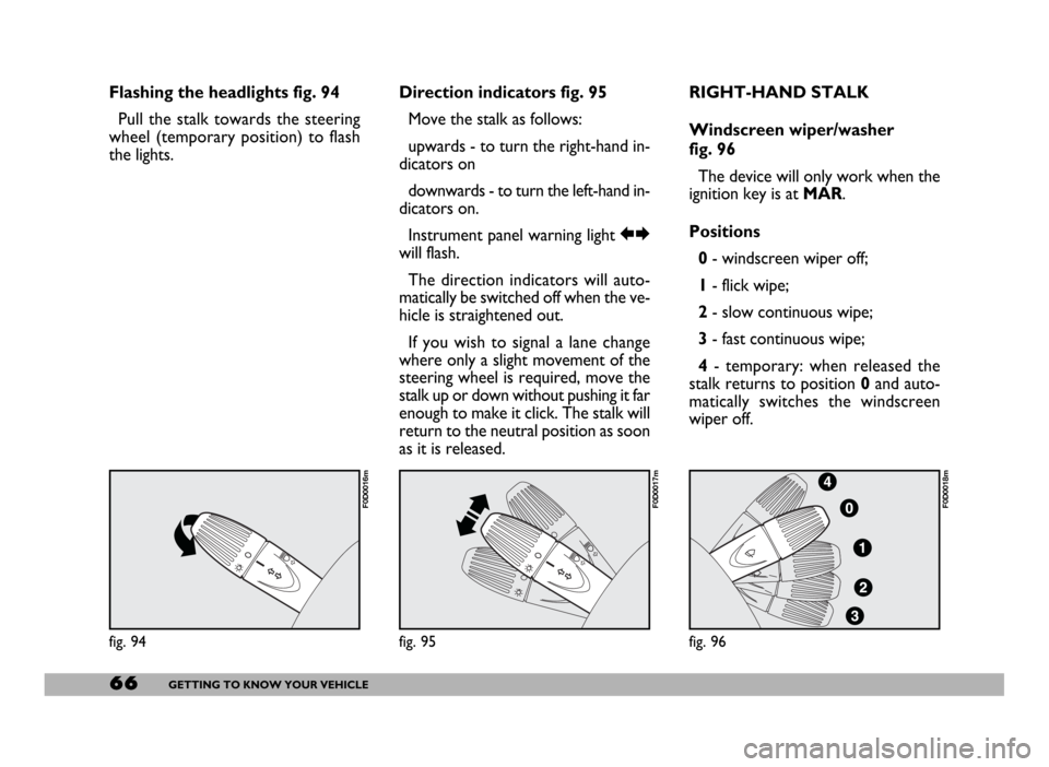
Flashing the headlights fig. 94
Pull the stalk towards the steering
wheel (temporary position) to flash
the lights.Direction indicators fig. 95
Move the stalk as follows:
upwards - to turn the right-hand in-
dicators on
downwards - to turn the left-hand in-
dicators on.
Instrument panel warning light RE
will flash.
The direction indicators will auto-
matically be switched off when the ve-
hicle is straightened out.
If you wish to signal a lane change
where only a slight movement of the
steering wheel is required, move the
stalk up or down without pushing it far
enough to make it click. The stalk will
return to the neutral position as soon
as it is released.RIGHT-HAND STALK
Windscreen wiper/washer
fig. 96
The device will only work when the
ignition key is at MAR.
Positions
0- windscreen wiper off;
1- flick wipe;
2- slow continuous wipe;
3- fast continuous wipe;
4- temporary: when released the
stalk returns to position 0and auto-
matically switches the windscreen
wiper off.
fig. 94
F0D0016m
fig. 95
F0D0017m
fig. 96
F0D0018m
Page 70 of 258
69GETTING TO KNOW YOUR VEHICLE
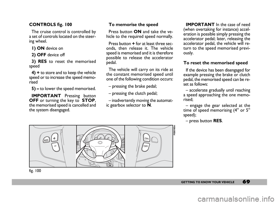
CONTROLS fig. 100
The cruise control is controlled by
a set of controls located on the steer-
ing wheel.
1) ONdevice on
2) OFFdevice off
3) RESto reset the memorised
speed
4) +to store and to keep the vehicle
speed or to increase the speed memo-
rised
5) – to lower the speed memorised.
IMPORTANTPressing button
OFFor turning the key to STOP,
the memorised speed is cancelled and
the system disengaged.IMPORTANTIn the case of need
(when overtaking for instance) accel-
eration is possible simply pressing the
accelerator pedal; later, releasing the
accelerator pedal, the vehicle will re-
turn to the speed memorised previ-
ously.
To reset the memorised speed
If the device has been disengaged for
example pressing the brake or clutch
pedal, the memorised speed can be re-
set as follows:
– accelerate gradually until reaching
a speed approaching the one memo-
rised;
– engage the gear selected at the
time of speed memorising (4
thor 5th
speed);
– press button RES. To memorise the speed
Press button ONand take the ve-
hicle to the required speed normally.
Press button +for at least three sec-
onds, then release it. The vehicle
speed is memorised and it is therefore
possible to release the accelerator
pedal.
The vehicle will carry on its ride at
the constant memorised speed until
one of the following condition occurs:
– pressing the brake pedal;
– pressing the clutch pedal;
– inadvertently moving the automat-
ic gearbox selector to N.
fig. 100
F0D0160m
Page 73 of 258
72GETTING TO KNOW YOUR VEHICLE
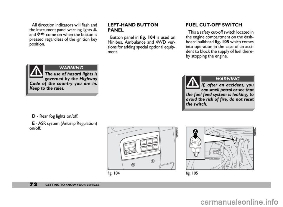
fig. 104
F0D00164m
fig. 105
F0D105m
All direction indicators will flash and
the instrument panel warning lights r
and ycome on when the button is
pressed regardless of the ignition key
position.FUEL CUT-OFF SWITCH
This a safety cut-off switch located in
the engine compartment on the dash-
board bulkhead fig. 105which comes
into operation in the case of an acci-
dent to block the supply of fuel there-
by stopping the engine.
D- Rear fog lights on/off.
E- ASR system (Antislip Regulation)
on/off.LEFT-HAND BUTTON
PANEL
Button panel in fig. 104is used on
Minibus, Ambulance and 4WD ver-
sions for adding special optional equip-
ment.
The use of hazard lights is
governed by the Highway
Code of the country you are in.
Keep to the rules.
WARNING
If, after an accident, you
can smell petrol or see that
the fuel feed system is leaking, to
avoid the risk of fire, do not reset
the switch.
WARNING
Page 74 of 258
73GETTING TO KNOW YOUR VEHICLE
Inspect the vehicle carefully to make
sure there is no fuel leak in the en-
gine compartment, under the vehicle
or near the fuel tank.
If you cannot see any fuel leaks and
the vehicle is in a fit state to continue
its journey, press button A-fig. 105
to reactivate the fuel supply system, as
illustrated.
Remember to turn the ignition key
to STOPto prevent running the bat-
tery down.INTERIOR
EQUIPMENT
GLOVE COMPARTMENT/
ODDMENT TRAY
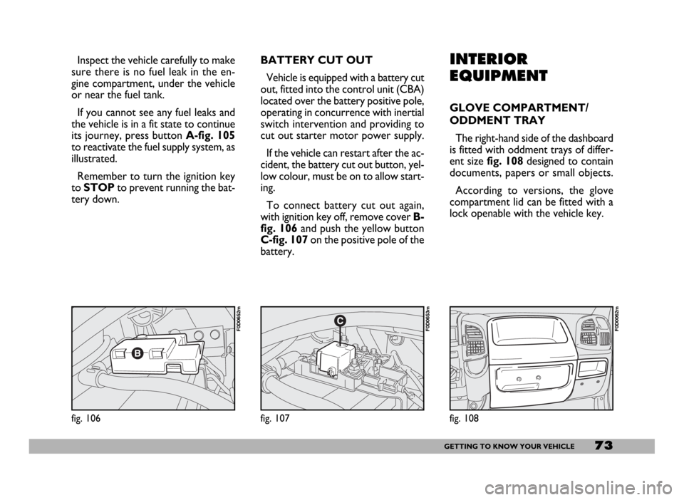
The right-hand side of the dashboard
is fitted with oddment trays of differ-
ent sizefig. 108designed to contain
documents, papers or small objects.
According to versions, the glove
compartment lid can be fitted with a
lock openable with the vehicle key.
fig. 108
F0D0062m
fig. 106
F0D0652m
fig. 107
F0D0653m
BATTERY CUT OUT
Vehicle is equipped with a battery cut
out, fitted into the control unit (CBA)
located over the battery positive pole,
operating in concurrence with inertial
switch intervention and providing to
cut out starter motor power supply.
If the vehicle can restart after the ac-
cident, the battery cut out button, yel-
low colour, must be on to allow start-
ing.
To connect battery cut out again,
with ignition key off, remove cover B-
fig. 106 and push the yellow button
C-fig. 107 on the positive pole of the
battery.
Page 76 of 258
75GETTING TO KNOW YOUR VEHICLE
When tilted, the box cover becomes
a writing/reading desk with a clip to
hold sheets/papers, similar to that
shown in fig. 112.
Refrigerator version (food box)
In the refrigerator version, the box
has an internal space of about 12 litres
capacity that can contain 2 one and a
half litre bottles. In this version the
box is insulated and it is fitted with an
electric device to warm up or cool the
box interior as required.
This box can be used as food con-
tainer. Food shall be suitably packed
to avoid direct contact with the inner
walls of the box.
When used for cooling, a tempera-
ture difference of approx. 18 °C can
be achieved between the temperature
inside the box and that of the passen-
ger compartment after a certain time
of operation (with insulated cover and
plug closed). The lowest possible tem-
perature that can be reached in any
case is not lower than 8 -10 °C.To prevent the risk of running the bat-
tery down, the system is connected via
the ignition key; as a result the box will
only work when the engine is running.
You should remove perishables from
the box if you leave the vehicle parked
for longer than two hours.
For proper operation it is necessary
that ventilation grids (outside the box
and on one of the inside walls) should
not be clogged.
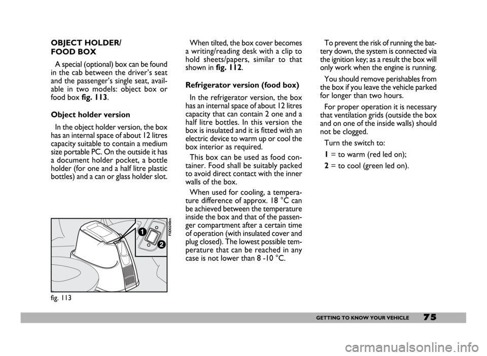
Turn the switch to:
1= to warm (red led on);
2= to cool (green led on).
fig. 113
F0D0249m
OBJECT HOLDER/
FOOD BOX
A special (optional) box can be found
in the cab between the driver’s seat
and the passenger’s single seat, avail-
able in two models: object box or
food box fig. 113.
Object holder version
In the object holder version, the box
has an internal space of about 12 litres
capacity suitable to contain a medium
size portable PC. On the outside it has
a document holder pocket, a bottle
holder (for one and a half litre plastic
bottles) and a can or glass holder slot.