climate control FIAT DUCATO 244 2005 3.G Owners Manual
[x] Cancel search | Manufacturer: FIAT, Model Year: 2005, Model line: DUCATO 244, Model: FIAT DUCATO 244 2005 3.GPages: 258, PDF Size: 4.05 MB
Page 56 of 258
55GETTING TO KNOW YOUR VEHICLE
Certain versions can be fitted, in ad-
dition to the climate control system,
with an optional heater to be set un-
der the last seat row and controlled
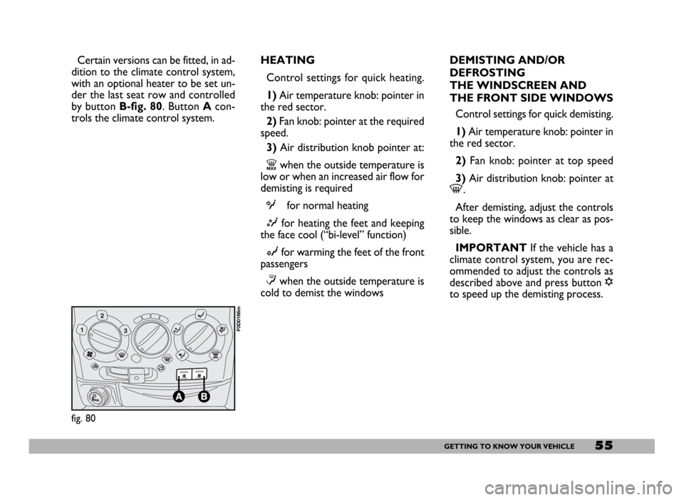
by button B-fig. 80. Button Acon-
trols the climate control system.HEATING
Control settings for quick heating.
1)Air temperature knob: pointer in
the red sector.
2) Fan knob: pointer at the required
speed.
3) Air distribution knob pointer at:
Zwhen the outside temperature is
low or when an increased air flow for
demisting is required
Ofor normal heating
Mfor heating the feet and keeping
the face cool (“bi-level” function)
Nfor warming the feet of the front
passengers
≤when the outside temperature is
cold to demist the windowsDEMISTING AND/OR
DEFROSTING
THE WINDSCREEN AND
THE FRONT SIDE WINDOWS
Control settings for quick demisting.
1) Air temperature knob: pointer in
the red sector.
2) Fan knob: pointer at top speed
3) Air distribution knob: pointer at
-.
After demisting, adjust the controls
to keep the windows as clear as pos-
sible.
IMPORTANT If the vehicle has a
climate control system, you are rec-
ommended to adjust the controls as
described above and press button √
to speed up the demisting process.
fig. 80
F0D0166m
Page 58 of 258
57GETTING TO KNOW YOUR VEHICLE
CLIMATE CONTROL
SYSTEM
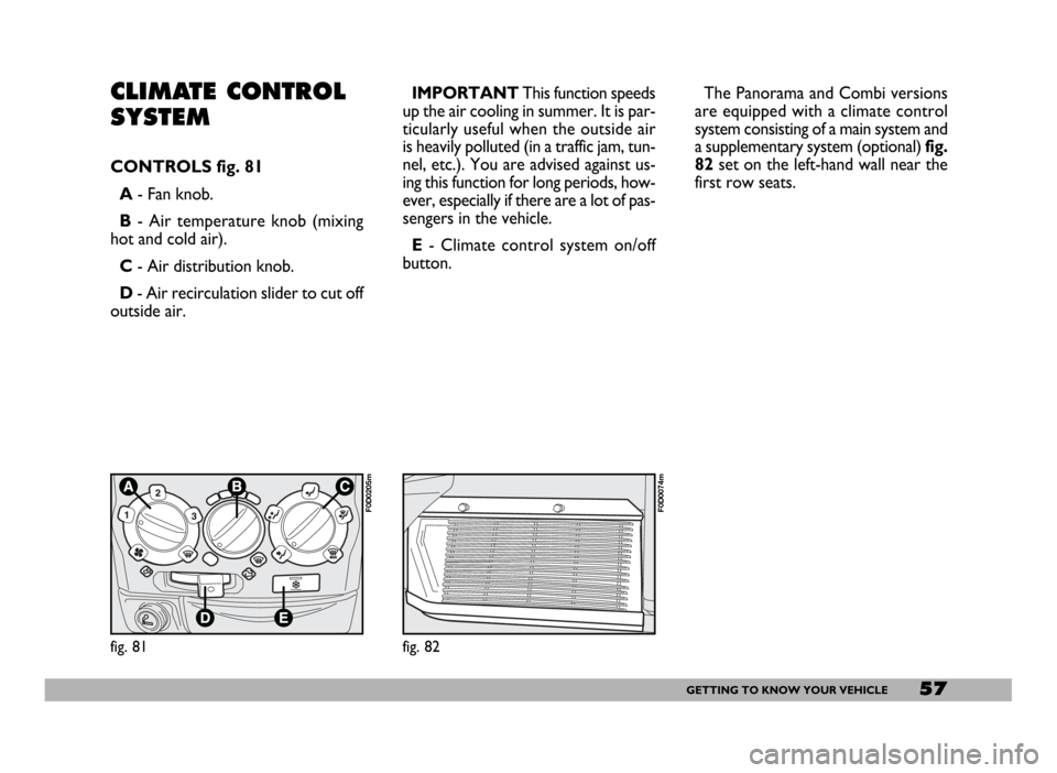
CONTROLS fig. 81
A- Fan knob.
B- Air temperature knob (mixing
hot and cold air).
C- Air distribution knob.
D- Air recirculation slider to cut off
outside air.IMPORTANTThis function speeds
up the air cooling in summer. It is par-
ticularly useful when the outside air
is heavily polluted (in a traffic jam, tun-
nel, etc.). You are advised against us-
ing this function for long periods, how-
ever, especially if there are a lot of pas-
sengers in the vehicle.
E- Climate control system on/off
button.The Panorama and Combi versions
are equipped with a climate control
system consisting of a main system and
a supplementary system (optional) fig.
82set on the left-hand wall near the
first row seats.
fig. 81
F0D0205m
fig. 82
F0D0074m
Page 59 of 258
58GETTING TO KNOW YOUR VEHICLE
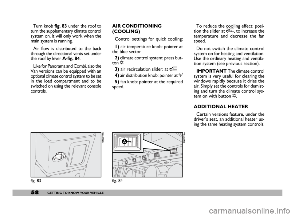
Turn knob fig. 83 under the roof to
turn the supplementary climate control
system on. It will only work when the
main system is running.
Air flow is distributed to the back
through the directional vents set under
the roof by lever A-fig. 84.
Like for Panorama and Combi, also the
Van versions can be equipped with an
optional climate control system to be set
in the load compartment and to be
switched on using the relevant console
controls.AIR CONDITIONING
(COOLING)
Control settings for quick cooling:
1)air temperature knob: pointer at
the blue sector
2)climate control system: press but-
ton √
3)air recirculation slider: at Ò
4) air distribution knob: pointer at O
5)fan knob: pointer at the required
speed.To reduce the cooling effect: posi-
tion the slider at Ú, to increase the
temperature and decrease the fan
speed.
Do not switch the climate control
system on for heating and ventilation.
Use the ordinary heating and ventila-
tion system (see previous section).
IMPORTANT The climate control
system is very useful for clearing the
windows rapidly because it dries the
air. Simply set the controls for demist-
ing and turn the climate control sys-
tem on with button √.
ADDITIONAL HEATER
Certain versions feature, under the
driver’s seat, an additional heater us-
ing the same heating system controls.
fig. 83
F0D0049m
fig. 84
F0D0075m
Page 66 of 258
65GETTING TO KNOW YOUR VEHICLE
STEERING COLUMN
STALKS
LEFT-HAND STALK
The left-hand stalk operates most of
the external lights.
The external lights can only be
switched on when the ignition key is
at MAR. The instrument panel and
the heating/ventilation (or climate con-
trol system) controls and the cigar
lighter ring will come on with the ex-
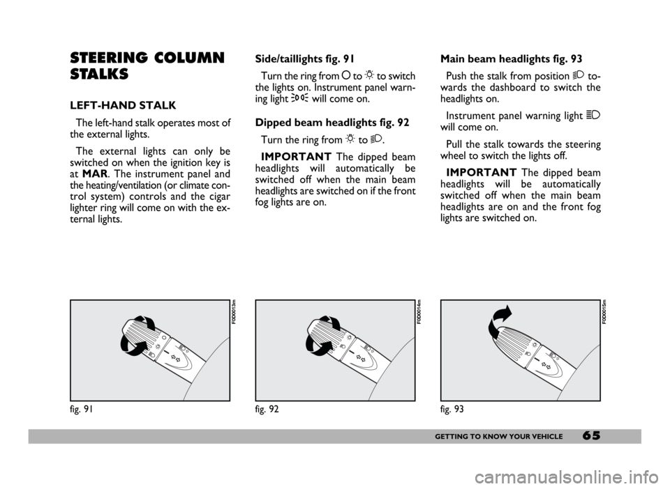
ternal lights.Side/taillights fig. 91
Turn the ring from åto 6to switch
the lights on. Instrument panel warn-
ing light 3will come on.
Dipped beam headlights fig. 92
Turn the ring from 6to 2.
IMPORTANTThe dipped beam
headlights will automatically be
switched off when the main beam
headlights are switched on if the front
fog lights are on.Main beam headlights fig. 93
Push the stalk from position 2to-
wards the dashboard to switch the
headlights on.
Instrument panel warning light 1
will come on.
Pull the stalk towards the steering
wheel to switch the lights off.
IMPORTANTThe dipped beam
headlights will be automatically
switched off when the main beam
headlights are on and the front fog
lights are switched on.
fig. 91
F0D0013m
fig. 92
F0D0014m
fig. 93
F0D0015m
Page 126 of 258
125GETTING THE BEST OUT OF YOUR VEHICLE
Electric devices
Use electric devices for the neces-
sary time only. The heated rear win-
dow, fog lights, windscreen wipers,
heater fan require large amounts of
electricity and increasing the request
for power will also increase fuel con-
sumption (up to +25% when driving in
towns).
Climate control system
The climate control system is an ad-
ditional load which greatly affects the
engine leading to higher consumption.
When the temperature outside the
vehicle allows it, use the air vents
where possible.
DRIVING STYLE
Starting
Do not warm the engine when the
vehicle is stationary or at high or low
speed: in this way the engine will warm
up gradually increasing consumption
and emissions. You should drive off
slowly straight away avoiding high revs
so that the engine will warm up more
quickly.Unnecessary actions
Avoid revving the engine when
stopped at traffic lights or before
switching off the engine and avoid dou-
bling the clutch as these actions have
no purpose on modern vehicles and
serve only to increase consumption
and pollution.
Gear selections
As soon as the traffic and road con-
ditions allow it, shift to a higher gear.
Using a low gear to liven up accelera-
tion greatly increases consumption. In
the same way improper use of high
gears will increase consumption, emis-
sions and engine wear.
On passenger transportation versions
fitted with 2.3, 2.8 JTD and 2.8 JTD
POWER engines, fuel consumption can
be optimised by starting (on level road)
in 2nd gear instead of 1st gear.Top speeds
Fuel consumption increases consid-
erably as speed increases. Your speed
should be kept as even as possible and
superfluous braking and acceleration
avoided as this increases both con-
sumption and emissions.
Acceleration
Accelerating violently increasing the
revs will greatly affect consumption
and emissions; acceleration should be
gradual and should not exceed the
maximum torque.
Page 154 of 258
153IN AN EMERGENCY
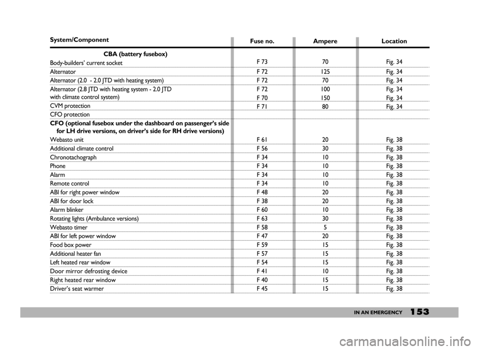
System/Component
CBA (battery fusebox)
Body-builders’ current socket
Alternator
Alternator (2.0 - 2.0 JTD with heating system)
Alternator (2.8 JTD with heating system - 2.0 JTD
with climate control system)
CVM protection
CFO protection
CFO (optional fusebox under the dashboard on passenger’s side
for LH drive versions, on driver’s side for RH drive versions)
Webasto unit
Additional climate control
Chronotachograph
Phone
Alarm
Remote control
ABI for right power window
ABI for door lock
Alarm blinker
Rotating lights (Ambulance versions)
Webasto timer
ABI for left power window
Food box power
Additional heater fan
Left heated rear window
Door mirror defrosting device
Right heated rear window
Driver’s seat warmerFuse no.
F 73
F 72
F 72
F 72
F 70
F 71
F 61
F 56
F 34
F 34
F 34
F 34
F 48
F 38
F 60
F 63
F 58
F 47
F 59
F 57
F 54
F 41
F 40
F 45Ampere
70
125
70
100
150
80
20
30
10
10
10
10
20
20
10
30
5
20
15
15
15
10
15
15Location
Fig. 34
Fig. 34
Fig. 34
Fig. 34
Fig. 34
Fig. 34
Fig. 38
Fig. 38
Fig. 38
Fig. 38
Fig. 38
Fig. 38
Fig. 38
Fig. 38
Fig. 38
Fig. 38
Fig. 38
Fig. 38
Fig. 38
Fig. 38
Fig. 38
Fig. 38
Fig. 38
Fig. 38
Page 156 of 258
155IN AN EMERGENCY
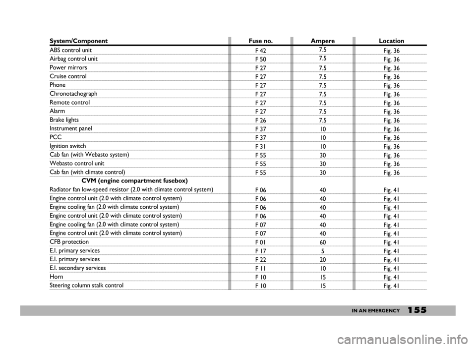
System/Component
ABS control unit
Airbag control unit
Power mirrors
Cruise control
Phone
Chronotachograph
Remote control
Alarm
Brake lights
Instrument panel
PCC
Ignition switch
Cab fan (with Webasto system)
Webasto control unit
Cab fan (with climate control)
CVM (engine compartment fusebox)
Radiator fan low-speed resistor (2.0 with climate control system)
Engine control unit (2.0 with climate control system)
Engine cooling fan (2.0 with climate control system)
Engine control unit (2.0 with climate control system)
Engine cooling fan (2.0 with climate control system)
Engine control unit (2.0 with climate control system)
CFB protection
E.I. primary services
E.I. primary services
E.I. secondary services
Horn
Steering column stalk controlFuse no.
F 42
F 50
F 27
F 27
F 27
F 27
F 27
F 27
F 26
F 37
F 37
F 31
F 55
F 55
F 55
F 06
F 06
F 06
F 06
F 07
F 07
F 01
F 17
F 22
F 11
F 10
F 10Ampere
7.5
7.5
7.5
7.5
7.5
7.5
7.5
7.5
7.5
10
10
10
30
30
30
40
40
40
40
40
40
60
5
20
10
15
15Location
Fig. 36
Fig. 36
Fig. 36
Fig. 36
Fig. 36
Fig. 36
Fig. 36
Fig. 36
Fig. 36
Fig. 36
Fig. 36
Fig. 36
Fig. 36
Fig. 36
Fig. 36
Fig. 41
Fig. 41
Fig. 41
Fig. 41
Fig. 41
Fig. 41
Fig. 41
Fig. 41
Fig. 41
Fig. 41
Fig. 41
Fig. 41
Page 157 of 258
156IN AN EMERGENCY
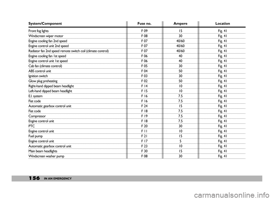
System/Component
Front fog lights
Windscreen wiper motor
Engine cooling fan 2nd speed
Engine control unit 2nd speed
Radiator fan 2nd speed remote switch coil (climate control)
Engine cooling fan 1st speed
Engine control unit 1st speed
Cab fan (climate control)
ABS control unit
Ignition switch
Glow plug preheating
Right-hand dipped beam headlight
Left-hand dipped beam headlight
E.I. system
Fiat code
Automatic gearbox control unit
Fiat code
Compressor
Engine control unit
PTC
Engine control unit
Fuel pump
Engine control unit
Automatic gearbox control unit
Main beam headlights
Windscreen washer pumpFuse no.
F 09
F 08
F 07
F 07
F 07
F 06
F 06
F 05
F 04
F 03
F 02
F 14
F 15
F 16
F 16
F 24
F 18
F 19
F 18
F 20
F 11
F 21
F 17
F 23
F 30
F 08Ampere
15
30
40/60
40/60
40/60
40
40
30
50
30
50
10
10
7.5
7.5
15
7.5
7.5
7.5
30
10
15
5
10
15
30Location
Fig. 41
Fig. 41
Fig. 41
Fig. 41
Fig. 41
Fig. 41
Fig. 41
Fig. 41
Fig. 41
Fig. 41
Fig. 41
Fig. 41
Fig. 41
Fig. 41
Fig. 41
Fig. 41
Fig. 41
Fig. 41
Fig. 41
Fig. 41
Fig. 41
Fig. 41
Fig. 41
Fig. 41
Fig. 41
Fig. 41
Page 244 of 258
243TECHNICAL SPECIFICATIONS
FUEL CONSUMPTION - CO2EMISSIONS
RUNNING AND USE CONDITIONS AFFECTING FUEL CONSUMPTION
(examples and differences with respect to goods transportation vehicle data)
IMPORTANT
Although fuel consumption mea-
surements procedure aim at defining
realistic values, fuel consumption is in-
fluenced by factors such as:
Driving style and vehicle usehigh
speed, frequent acceleration, frequent
gear shifting, door-to-door deliveries,
etc.
Just for passenger transportation
versions with 2.3 and 2.8 JTD engines,
reduced consumption can be obtained
by starting (on level road) in 2nd gear
instead of 1st gear.
Traffic and road conditions
queues, bending roads, steep roads,
bad road surface, etc.Weather conditions and tem-
peratures
low temperatures, thinner air, wind,
rain etc…;
Vehicle conditions
Poor maintenance (tyre pressure, fil-
ters, spark plugs, etc.), damaged body-
work
Load conditions
Heavy weights, not optimal load dis-
tribution, large weights on roof rack,
etc.
Use of electric devices
Climate control, heater and electric
devices in general
Special conditions of use
Special vehicle conditions of use: roof
rack, trailer, open side windows, type
of tyres, etc.Special trim and adaptations
caravan, motor home, mega box, can-
vas cover, etc.
Some of these conditions are illus-
trated in these figures on the next
pages.
For more information, refer to the
advice in the chapter “Cheap running
that respects the environment.
The fuel consumption values shown
in the table in following pages were de-
fined according to the type-approval
specifications in European Directives.
Consumption values are defined by
means of the following procedures:
– an urban cycle: consisting of a
cold start and a simulated drive in city
streets;
– an extra-urban cycle: consisting
in frequent accelerations, in all gears,
Page 245 of 258
244TECHNICAL SPECIFICATIONS
simulating normal conditions of use.
Speed ranges from 0 to 120 km/h;
– average combined cyclecon-
sisting of 37% urban cycle and 63% ex-
tra-urban cycle.
IMPORTANT Road and traffic
conditions, weather, general con-
ditions of the vehicle, drivingstyle, fittings and accessories, use
of the climate control system,
load, roof racks and other situa-
tions penalising aerodynamic
penetration and effecting rolling
resistance will influence fuel con-
sumption rates which can be dif-
ferent from the values shown inthe table (see “Cheap running
that respects the environment”
in “Driving your car” chapter).
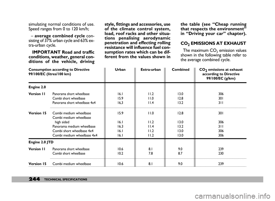
CO
2EMISSIONS AT EXHAUST
The maximum CO
2emission values
shown in the following table refer to
the average combined cycle.
Consumption according to Directive Urban Extra-urban Combined CO
2emissions at exhaust
99/100/EC (litres/100 km)according to Directive
99/100/EC (g/km)
Engine 2.0
Version 11Panorama short wheelbase 16.1 11.2 13.0 306
Combi short wheelbase 15.9 11.0 12.8 301
Panorama short wheelbase 4x4 16,3 11.4 13.2 311
Version 15Combi medium wheelbase 15.911.012.8 301
Combi medium wheelbase
high sided 16
.111.213.0 306
Panorama medium wheelbase 16
.311.413.2 311
Combi short wheelbase 4x4 16
.111.213.0 306
Combi medium wheelbase 4x4 16.111.213.0 306
Engine 2.0 JTD
Version 11Panorama short wheelbase 10.6 8.1 9.0 239
Combi short wheelbase 10.2 7.8 8.7 230
Version 15Combi medium wheelbase 10.68.19.0 239