steering FIAT DUCATO 244 2005 3.G Owners Manual
[x] Cancel search | Manufacturer: FIAT, Model Year: 2005, Model line: DUCATO 244, Model: FIAT DUCATO 244 2005 3.GPages: 258, PDF Size: 4.05 MB
Page 6 of 258
5GETTING TO KNOW YOUR VEHICLE
G G
E E
T T
T T
I I
N N
G G
T T
O O
K K
N N
O O
W W
Y Y
O O
U U
R R
V V
E E
H H
I I
C C
L L
E E
DASHBOARD
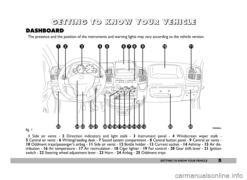
The presence and the position of the instruments and warning lights may vary according to the vehicle version.
1Side air vents - 2Direction indicators and light stalk - 3Instrument panel - 4Windscreen wiper stalk -
5Central air vents - 6Writing/reading desk - 7Sound system compartment - 8Central button panel -9Central air vents -
10Oddment trays/passenger’s airbag - 11Side air vents - 12Bottle holder - 13Current socket - 14Ashtray - 15Air dis-
tribution - 16Air temperature - 17Air recirculation -18Cigar lighter - 19Fan control - 20Gear shift lever - 21Ignition
switch - 22Steering wheel adjustment lever - 23Horn - 24Airbag - 25Oddment trays
fig. 1F0D0080m
Page 7 of 258
6GETTING TO KNOW YOUR VEHICLE
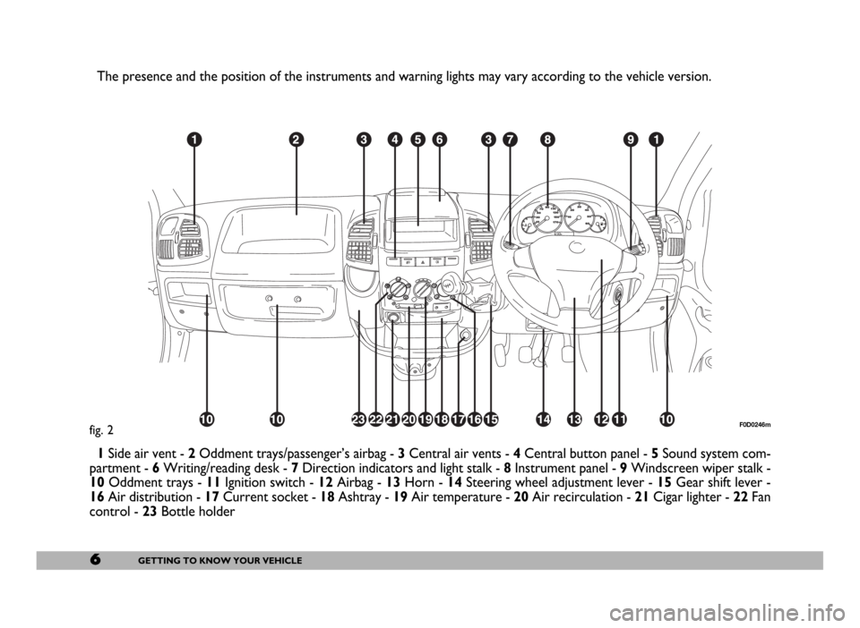
fig. 2F0D0246m
The presence and the position of the instruments and warning lights may vary according to the vehicle version.
1Side air vent - 2Oddment trays/passenger’s airbag - 3 Central air vents - 4Central button panel - 5Sound system com-
partment - 6Writing/reading desk - 7Direction indicators and light stalk - 8Instrument panel - 9Windscreen wiper stalk -
10Oddment trays - 11Ignition switch - 12Airbag - 13Horn - 14Steering wheel adjustment lever - 15Gear shift lever -
16Air distribution - 17Current socket - 18Ashtray - 19Air temperature - 20Air recirculation - 21Cigar lighter - 22Fan
control - 23Bottle holder
Page 13 of 258
12GETTING TO KNOW YOUR VEHICLE
OPERATION
The electronic alarm fitted on the Fi-
at Ducato is controlled by the receiv-
er located on the front ceiling light and
is switched on by means of the radio-
frequency remote control.
Volumetric protection sensors C-
fig. 8 are located in the ceiling light.
The alarm can only be switched on
when the ignition key is removed from
STOPor PARKposition.
The electronic alarm control unit in-
cludes also the alarm siren that can be
cut out.
To switch the electronic alarm
on: press button D-fig. 6 on the re-
mote control briefly. You will hear a
beep and the direction indicators will
flash for approximately three seconds
(only in countries where this is al-
lowed).
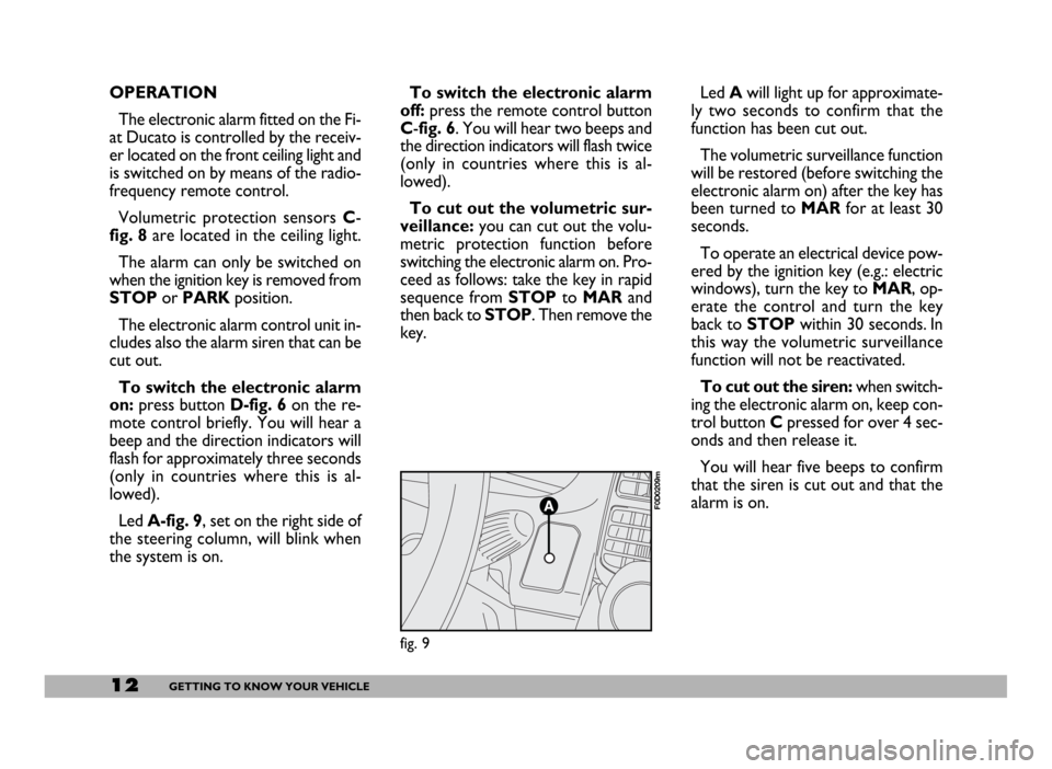
Led A-fig. 9, set on the right side of
the steering column, will blink when
the system is on.To switch the electronic alarm
off: press the remote control button
C-fig. 6. You will hear two beeps and
the direction indicators will flash twice
(only in countries where this is al-
lowed).
To cut out the volumetric sur-
veillance:you can cut out the volu-
metric protection function before
switching the electronic alarm on. Pro-
ceed as follows: take the key in rapid
sequence from STOP to MAR and
then back to STOP. Then remove the
key.Led Awill light up for approximate-
ly two seconds to confirm that the
function has been cut out.
The volumetric surveillance function
will be restored (before switching the
electronic alarm on) after the key has
been turned to MARfor at least 30
seconds.
To operate an electrical device pow-
ered by the ignition key (e.g.: electric
windows), turn the key to MAR, op-
erate the control and turn the key
back to STOP within 30 seconds. In
this way the volumetric surveillance
function will not be reactivated.
To cut out the siren:when switch-
ing the electronic alarm on, keep con-
trol button Cpressed for over 4 sec-
onds and then release it.
You will hear five beeps to confirm
that the siren is cut out and that the
alarm is on.
fig. 9
F0D0209m
Page 29 of 258
28GETTING TO KNOW YOUR VEHICLE
IGNITION SWITCH
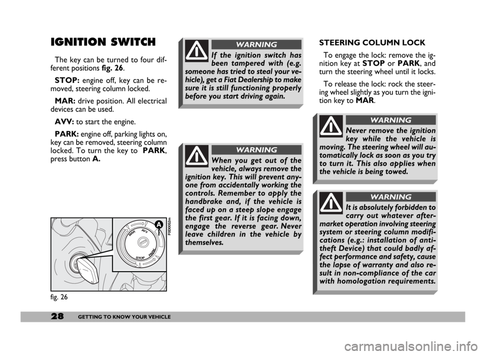
The key can be turned to four dif-
ferent positions fig. 26.
STOP:engine off, key can be re-
moved, steering column locked.
MAR:drive position. All electrical
devices can be used.
AVV:to start the engine.
PARK:engine off, parking lights on,
key can be removed, steering column
locked. To turn the key to PARK,
press button A.STEERING COLUMN LOCK
To engage the lock: remove the ig-
nition key at STOPor PARK, and
turn the steering wheel until it locks.
To release the lock: rock the steer-
ing wheel slightly as you turn the igni-
tion key to MAR.
fig. 26
F0D0052m
If the ignition switch has
been tampered with (e.g.
someone has tried to steal your ve-
hicle), get a Fiat Dealership to make
sure it is still functioning properly
before you start driving again.
WARNING
When you get out of the
vehicle, always remove the
ignition key. This will prevent any-
one from accidentally working the
controls. Remember to apply the
handbrake and, if the vehicle is
faced up on a steep slope engage
the first gear. If it is facing down,
engage the reverse gear. Never
leave children in the vehicle by
themselves.
WARNING
Never remove the ignition
key while the vehicle is
moving. The steering wheel will au-
tomatically lock as soon as you try
to turn it. This also applies when
the vehicle is being towed.
WARNING
It is absolutely forbidden to
carry out whatever after-
market operation involving steering
system or steering column modifi-
cations (e.g.: installation of anti-
theft Device) that could badly af-
fect performance and safety, cause
the lapse of warranty and also re-
sult in non-compliance of the car
with homologation requirements.
WARNING
Page 52 of 258
51GETTING TO KNOW YOUR VEHICLE
HEIGHT ADJUSTABLE
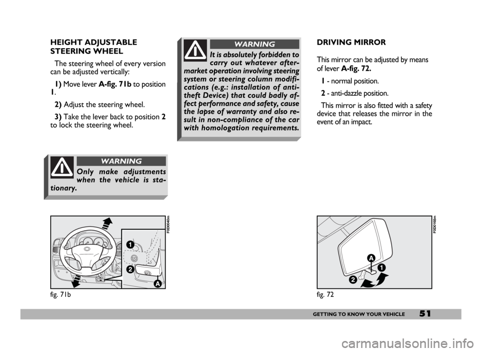
STEERING WHEEL
The steering wheel of every version
can be adjusted vertically:
1)Move lever A-fig. 71b to position
1.
2)Adjust the steering wheel.
3)Take the lever back to position 2
to lock the steering wheel.
fig. 71b
F0D0040m
Only make adjustments
when the vehicle is sta-
tionary.
WARNING
DRIVING MIRROR
This mirror can be adjusted by means
of lever A-fig. 72.
1- normal position.
2- anti-dazzle position.
This mirror is also fitted with a safety
device that releases the mirror in the
event of an impact.
fig. 72
F0D0168m
It is absolutely forbidden to
carry out whatever after-
market operation involving steering
system or steering column modifi-
cations (e.g.: installation of anti-
theft Device) that could badly af-
fect performance and safety, cause
the lapse of warranty and also re-
sult in non-compliance of the car
with homologation requirements.
WARNING
Page 66 of 258
65GETTING TO KNOW YOUR VEHICLE
STEERING COLUMN
STALKS
LEFT-HAND STALK
The left-hand stalk operates most of
the external lights.
The external lights can only be
switched on when the ignition key is
at MAR. The instrument panel and
the heating/ventilation (or climate con-
trol system) controls and the cigar
lighter ring will come on with the ex-
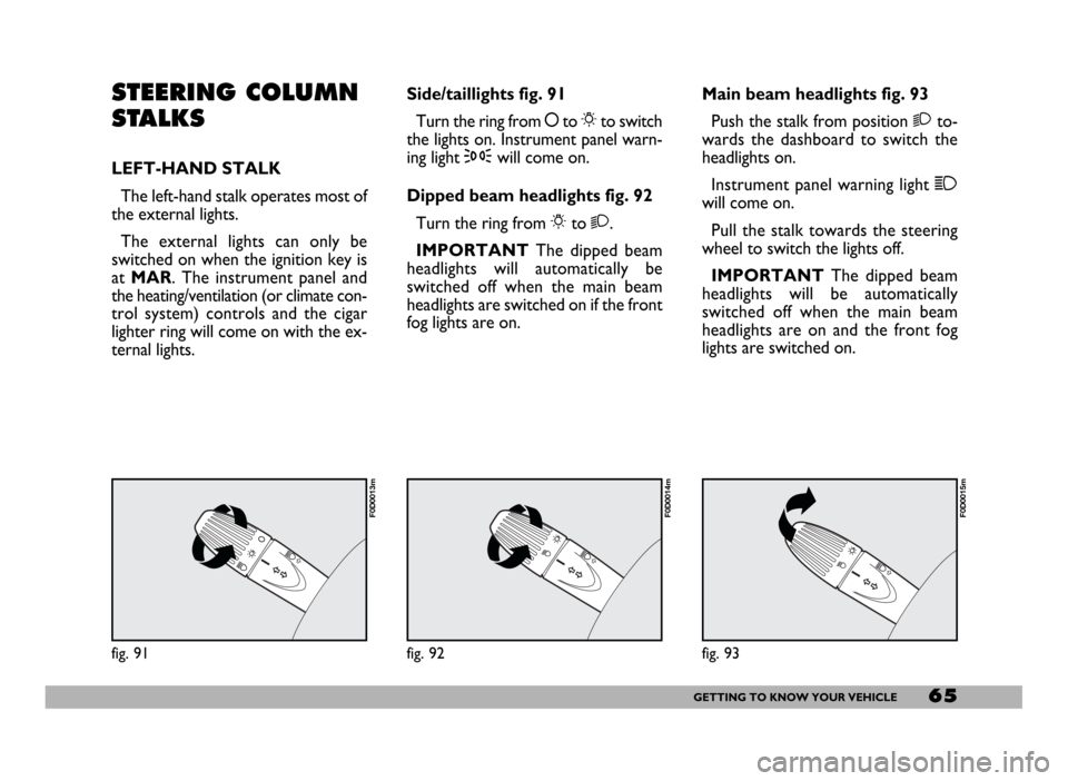
ternal lights.Side/taillights fig. 91
Turn the ring from åto 6to switch
the lights on. Instrument panel warn-
ing light 3will come on.
Dipped beam headlights fig. 92
Turn the ring from 6to 2.
IMPORTANTThe dipped beam
headlights will automatically be
switched off when the main beam
headlights are switched on if the front
fog lights are on.Main beam headlights fig. 93
Push the stalk from position 2to-
wards the dashboard to switch the
headlights on.
Instrument panel warning light 1
will come on.
Pull the stalk towards the steering
wheel to switch the lights off.
IMPORTANTThe dipped beam
headlights will be automatically
switched off when the main beam
headlights are on and the front fog
lights are switched on.
fig. 91
F0D0013m
fig. 92
F0D0014m
fig. 93
F0D0015m
Page 67 of 258
66GETTING TO KNOW YOUR VEHICLE
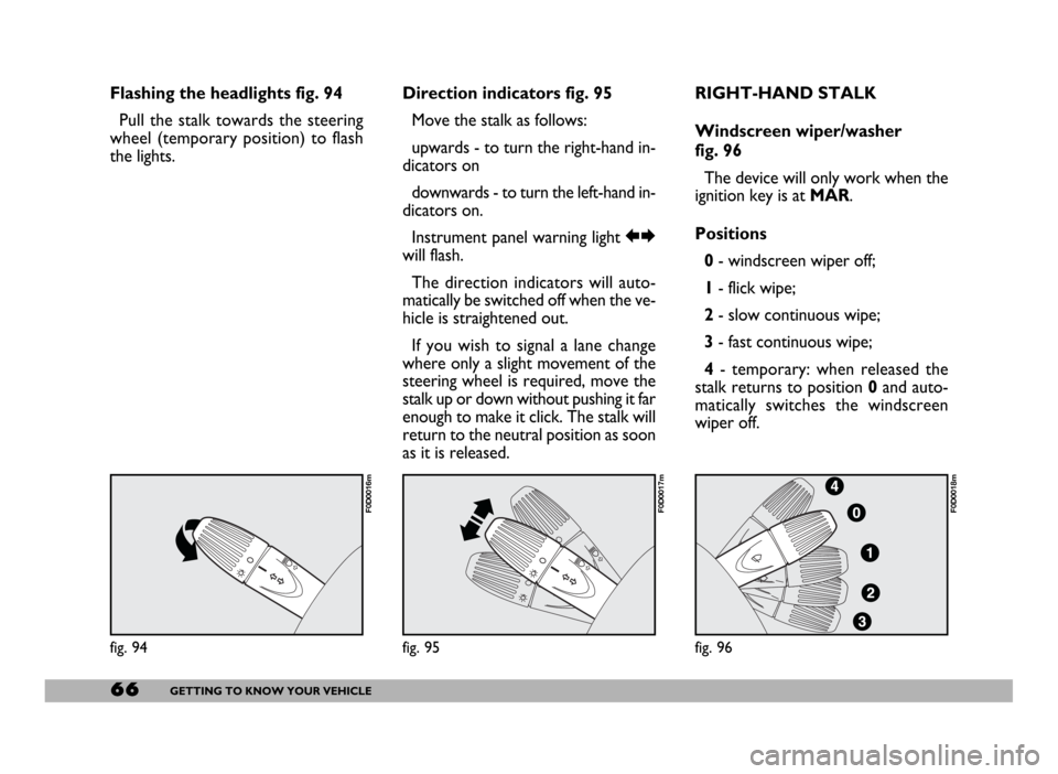
Flashing the headlights fig. 94
Pull the stalk towards the steering
wheel (temporary position) to flash
the lights.Direction indicators fig. 95
Move the stalk as follows:
upwards - to turn the right-hand in-
dicators on
downwards - to turn the left-hand in-
dicators on.
Instrument panel warning light RE
will flash.
The direction indicators will auto-
matically be switched off when the ve-
hicle is straightened out.
If you wish to signal a lane change
where only a slight movement of the
steering wheel is required, move the
stalk up or down without pushing it far
enough to make it click. The stalk will
return to the neutral position as soon
as it is released.RIGHT-HAND STALK
Windscreen wiper/washer
fig. 96
The device will only work when the
ignition key is at MAR.
Positions
0- windscreen wiper off;
1- flick wipe;
2- slow continuous wipe;
3- fast continuous wipe;
4- temporary: when released the
stalk returns to position 0and auto-
matically switches the windscreen
wiper off.
fig. 94
F0D0016m
fig. 95
F0D0017m
fig. 96
F0D0018m
Page 68 of 258
67GETTING TO KNOW YOUR VEHICLE
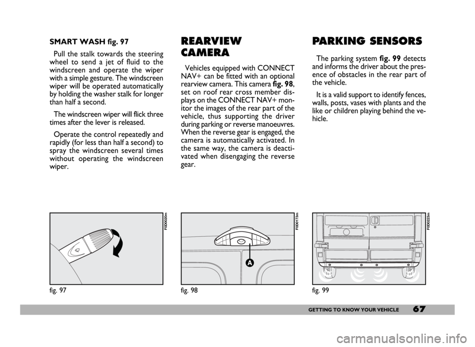
REARVIEW
CAMERA
Vehicles equipped with CONNECT
NAV+ can be fitted with an optional
rearview camera. This camerafig. 98,
set on roof rear cross member dis-
plays on the CONNECT NAV+ mon-
itor the images of the rear part of the
vehicle, thus supporting the driver
during parking or reverse manoeuvres.
When the reverse gear is engaged, the
camera is automatically activated. In
the same way, the camera is deacti-
vated when disengaging the reverse
gear.
PARKING SENSORS
The parking system fig. 99detects
and informs the driver about the pres-
ence of obstacles in the rear part of
the vehicle.
It is a valid support to identify fences,
walls, posts, vases with plants and the
like or children playing behind the ve-
hicle.
fig. 98
F0D0173m
SMART WASH fig. 97
Pull the stalk towards the steering
wheel to send a jet of fluid to the
windscreen and operate the wiper
with a simple gesture. The windscreen
wiper will be operated automatically
by holding the washer stalk for longer
than half a second.
The windscreen wiper will flick three
times after the lever is released.
Operate the control repeatedly and
rapidly (for less than half a second) to
spray the windscreen several times
without operating the windscreen
wiper.
fig. 97
F0D0020m
fig. 99
F0D0223m
Page 85 of 258
84GETTING TO KNOW YOUR VEHICLE
Improper use of the electri-
cal windows can be danger-
ous. Before and during their oper-
ation ensure that any passengers in
the vehicle are not at risk from the
moving glass either by personal ob-
jects getting caught in the mecha-
nism or by being injured by it di-
rectly.
WARNING
Always remove the ignition
key when you get out of the
vehicle to prevent the electric win-
dows being operated accidentally
and constituting a danger to the
people left in the vehicle
WARNING
BONNET
OPENING
Proceed as follows:
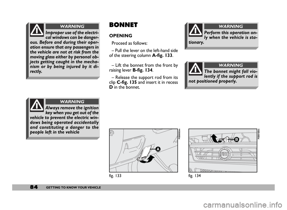
– Pull the lever on the left-hand side
of the steering column A-fig. 133.
– Lift the bonnet from the front by
raising lever B-fig. 134.
– Release the support rod from its
clipC-fig. 135and insert it in recess
Din the bonnet.
fig. 133
F0D0053m
fig. 134
F0D0180m
The bonnet might fall vio-
lently if the support rod is
not positioned properly.
WARNING
Perform this operation on-
ly when the vehicle is sta-
tionary.
WARNING
Page 91 of 258
90GETTING TO KNOW YOUR VEHICLE
FRONT AND SIDE
AIRBAGS
FRONT AIRBAGS
Description and operation
The front airbag (driver’s and passen-
ger’s) is a safety device which comes in-
to action in the event of a head-on col-
lision.
It consists of a cushion that inflates
instantaneously contained in a special
recess:
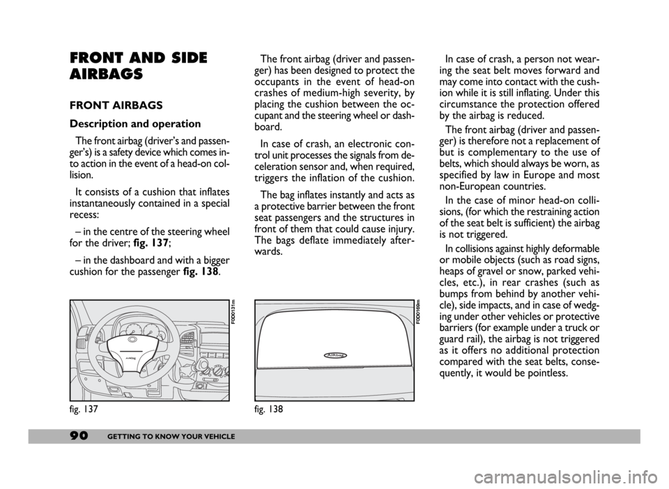
– in the centre of the steering wheel
for the driver; fig. 137;
– in the dashboard and with a bigger
cushion for the passenger fig. 138.The front airbag (driver and passen-
ger) has been designed to protect the
occupants in the event of head-on
crashes of medium-high severity, by
placing the cushion between the oc-
cupant and the steering wheel or dash-
board.
In case of crash, an electronic con-
trol unit processes the signals from de-
celeration sensor and, when required,
triggers the inflation of the cushion.
The bag inflates instantly and acts as
a protective barrier between the front
seat passengers and the structures in
front of them that could cause injury.
The bags deflate immediately after-
wards.
fig. 137
F0D0131m
fig. 138
F0D0169m
In case of crash, a person not wear-
ing the seat belt moves forward and
may come into contact with the cush-
ion while it is still inflating. Under this
circumstance the protection offered
by the airbag is reduced.
The front airbag (driver and passen-
ger) is therefore not a replacement of
but is complementary to the use of
belts, which should always be worn, as
specified by law in Europe and most
non-European countries.
In the case of minor head-on colli-
sions, (for which the restraining action
of the seat belt is sufficient) the airbag
is not triggered.
In collisions against highly deformable
or mobile objects (such as road signs,
heaps of gravel or snow, parked vehi-
cles, etc.), in rear crashes (such as
bumps from behind by another vehi-
cle), side impacts, and in case of wedg-
ing under other vehicles or protective
barriers (for example under a truck or
guard rail), the airbag is not triggered
as it offers no additional protection
compared with the seat belts, conse-
quently, it would be pointless.