ignition FIAT DUCATO BASE CAMPER 2015 Owner handbook (in English)
[x] Cancel search | Manufacturer: FIAT, Model Year: 2015, Model line: DUCATO BASE CAMPER, Model: FIAT DUCATO BASE CAMPER 2015Pages: 367, PDF Size: 19.73 MB
Page 78 of 367
The dead lock device therefore
offers the best possible protection
against break-in attempts. We
recommend engaging it whenever
the vehicle is parked and left
unattended.
34)
Device activation
The dead lock device is
automatically activated on every
door with two short presses on the
button
on the key with remote
control fig. 104.
Device activation is indicated by 3
flashes of the direction indicators
and a flash of the LED on button A
fig. 107 on the dashboard.If one or more of the doors is not
perfectly shut, the dead lock device
will not be activated, thus
preventing a person getting into the
car through the open door and,
on shutting, it, remaining stuck
inside the passenger compartment.
Device deactivation
The system is disabled
automatically on every door in the
following cases:❒if the mechanical key is turned to the
opening position in the driver's door;
❒by unlocking the doors using the
remote control;
❒by turning the ignition key to the
MAR-ON position.
SLIDING SIDE DOOR
35) 36)
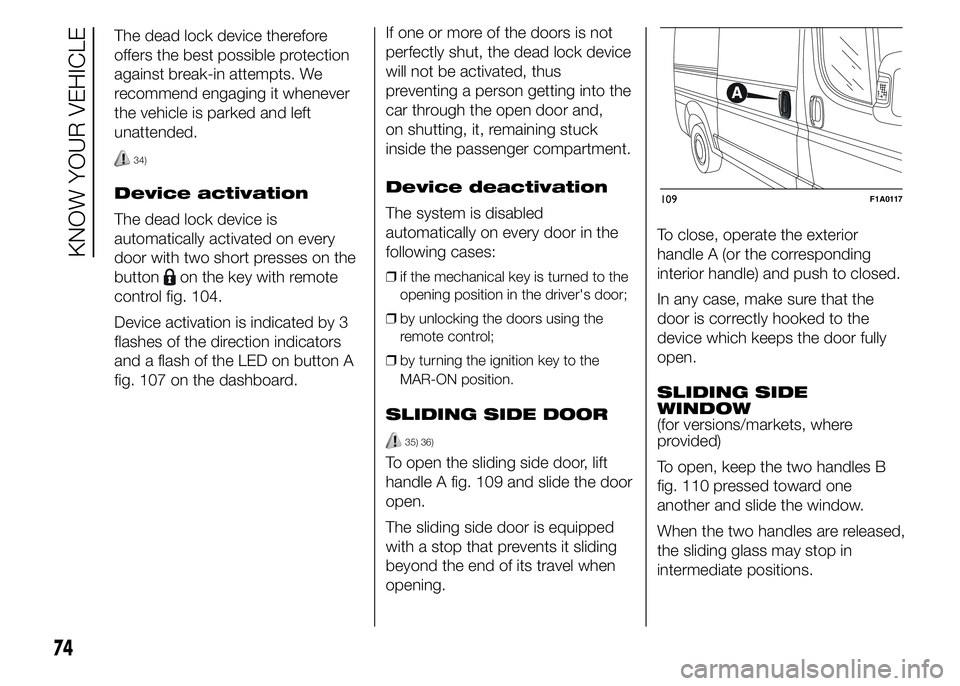
To open the sliding side door, lift
handle A fig. 109 and slide the door
open.
The sliding side door is equipped
with a stop that prevents it sliding
beyond the end of its travel when
opening.To close, operate the exterior
handle A (or the corresponding
interior handle) and push to closed.
In any case, make sure that the
door is correctly hooked to the
device which keeps the door fully
open.
SLIDING SIDE
WINDOW
(for versions/markets, where
provided)
To open, keep the two handles B
fig. 110 pressed toward one
another and slide the window.
When the two handles are released,
the sliding glass may stop in
intermediate positions.
109F1A0117
74
KNOW YOUR VEHICLE
Page 82 of 367
ELECTRIC WINDOWS
ELECTRIC
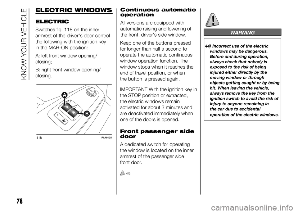
Switches fig. 118 on the inner
armrest of the driver's door control
the following with the ignition key
in the MAR-ON position:
A: left front window opening/
closing;
B: right front window opening/
closing.Continuous automatic
operation
All versions are equipped with
automatic raising and lowering of
the front, driver's side window.
Keep one of the buttons pressed
for longer than half a second to
operate the automatic continuous
window operation function. The
window stops when it reaches the
end of travel position, or when
the button is pressed again.
IMPORTANT With the ignition key in
the STOP position or extracted,
the electric windows remain
activated for about 3 minutes and
are deactivated immediately when
one of the doors is opened.
Front passenger side
door
A dedicated switch for operating
the window is located on the inner
armrest of the passenger side
front door.
44)
WARNING
44) Incorrect use of the electric
windows may be dangerous.
Before and during operation,
always check that nobody is
exposed to the risk of being
injured either directly by the
moving window or through
objects getting caught or by being
hit. When leaving the vehicle,
always remove the key from the
ignition switch to avoid the risk of
injury to anyone remaining in
the car due to accidental
operation of the electric windows.
118F1A0125
78
KNOW YOUR VEHICLE
Page 85 of 367
HEADLIGHTS
LIGHT BEAM
ALIGNMENT
The correct alignment of the
headlights is essential for the
comfort and safety of the driver and
other road users. To ensure the
best visibility when travelling with
the headlights on, the headlight
alignment must be correct. Contact
a Fiat Dealership to have the
headlights checked and adjusted.
HEADLIGHT
ALIGNMENT
CORRECTOR
This device works with the ignition
key in the MAR-ON position and
the dipped beam headlights on.
The vehicle tilts backwards when it
is laden, raising the beam.
The beams must therefore be
realigned in this case.Headlight alignment
adjustment
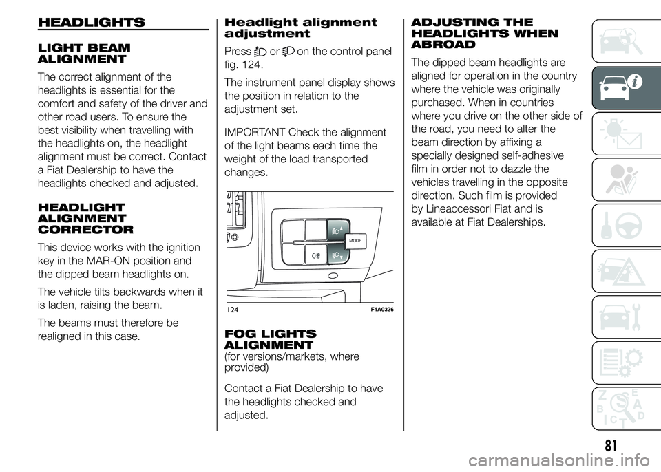
Pressoron the control panel
fig. 124.
The instrument panel display shows
the position in relation to the
adjustment set.
IMPORTANT Check the alignment
of the light beams each time the
weight of the load transported
changes.
FOG LIGHTS
ALIGNMENT
(for versions/markets, where
provided)
Contact a Fiat Dealership to have
the headlights checked and
adjusted.ADJUSTING THE
HEADLIGHTS WHEN
ABROAD
The dipped beam headlights are
aligned for operation in the country
where the vehicle was originally
purchased. When in countries
where you drive on the other side of
the road, you need to alter the
beam direction by affixing a
specially designed self-adhesive
film in order not to dazzle the
vehicles travelling in the opposite
direction. Such film is provided
by Lineaccessori Fiat and is
available at Fiat Dealerships.
MODEMODE
124F1A0326
81
Page 94 of 367
The TPMS uses wireless devices
with electronic sensors mounted on
the wheel rims to constantly
monitor the value of tyre pressure.
The sensors mounted on each
wheel as part of the valve stem
transmit various information of the
tyres to the receiver module, in
order to calculate the pressure.
WARNING Monitoring and
maintaining the correct pressure in
all four tyres are particularly
important.
Tyre pressure
monitoring system
low pressure
warnings
The system warns the driver if one
or more tyres are flat by switching
on the warning light
on the
instrument panel (together with a
warning message and an acoustic
signal).In this case, stop the vehicle as
soon as possible, check the
inflation pressure of each tyre and
inflate to the cold tyre pressure
value prescribed for the vehicle.
The system will automatically
update and after receiving the tyre
pressure update the tyre pressure
control warning light switches
off. You may need to drive
the vehicle for about 20 minutes at
a speed higher than 20 km/h to
allow the system to receive this
information.
TPMS operation faults
The system fault is indicated by
warning light
which first flashes
for 75 seconds and then stays
on steadily. This can occur in any of
the following situations:
❒interference caused by electronic
devices or radio frequency emissions
similar to those of the TPM sensors.
❒Application of tinted films which
interfere with the signals of the radio
waves.
❒Presence of snow or ice on the
wheels or the wheel arches.
❒Use of snow chains.❒Use of wheels/tyres not equipped
with TPM sensors.
❒The space-saver wheel is not
equipped with the tyre pressure
control sensor. Therefore, the tyre
pressure is not controlled by the
system.
❒If the space-saver wheel replaces a
tyre with a pressure lower than the
insufficient pressure limit, an acoustic
signal will be emitted and the warning
light
will switch on at the next
ignition cycle.
❒When the original tyre is repaired or
replaced and it is mounted back on
the vehicle to replace the space-
saver wheel, the TPMS will update
automatically and the warning light
will switch off, provided that the
pressure of none of the four tyres is
below the insufficient pressure limit.
You may need to drive the vehicle for
about 20 minutes at a speed higher
than 20 km/h to allow the TPMS
to receive this information.
90
KNOW YOUR VEHICLE
Page 109 of 367
❒vehicle in motion (e.g. when driving
on roads with a gradient);
❒stopping the engine through the
Start&Stop system for more than
about three minutes.
❒automatic climate control system for
adjusting the thermal comfort level or
to enable MAX-DEF function.
With a gear engaged, the engine
can be automatically restarted only
by fully depressing the clutch pedal.
NoteIf the engine stops and this is
not desired, due for example to the
clutch pedal being released sharply
with a gear engaged, if the Start&Stop
system is active, the engine can be
restarted by fully depressing the clutch
pedal or by placing the gear lever in
neutral.
NoteIf the clutch is not pressed, when
approx. three minutes have elapsed
since the engine was stopped, the
engine can only be restarted using the
key.
SAFETY FUNCTIONS
In engine cut-out conditions
through the Start&Stop system, if
the driver unfastens his/her seat
belt and opens the driver's door or
the passenger door, the engine
can be restarted only by using the
key. The driver is notified of this
condition by a buzzer, through the
warning light flashing in the
instrument panel and, where
provided, by a message in the
display.
"ENERGY SAVING"
FUNCTION
(for versions/markets, where
provided)
If, after the engine has been
automatically restarted, the driver
does not take any action for a
period of about 3 minutes,
the Start&Stop system will
definitively stop the engine to avoid
fuel consumption. The engine
can only be started using the key in
such cases.
NoteIn any case, it is possible to keep
the engine running by deactivating
the Start&Stop system.
IRREGULAR
OPERATION
In the event of malfunction, the
Start&Stop system is deactivated.
The driver is informed about the
fault through the switching on of the
icon together with a message
on the display. In this case, contact
a Fiat Dealership.
VEHICLE INACTIVITY
In the event of vehicle inactivity,
special attention must be paid to
the disconnection of the battery
power supply. Proceed as follows:
detach connector A fig. 134 (by
pressing button B) from sensor C
for monitoring the status of the
battery installed on the negative
battery pole D. This sensor should
never be disconnected from the
pole except if the battery is
replaced.
87) 88)
IMPORTANT After turning the
ignition key to STOP, wait at least 1
minute before disconnecting the
electrical supply to the battery.
105
Page 114 of 367
In order to avoid these problems,
different types of diesel are
distributed according to the
season: summer type, winter type
and arctic type (cold/mountain
areas). If refuelling with diesel fuel
whose specifications are not
suitable for the current temperature,
it is advisable to mix TUTELA
DIESEL ART additive in the
proportions shown on the
container. Pour the additive into the
tank before the diesel fuel.
When using or parking the vehicle
for a long time in the mountains
or cold areas, it is advisable to
refuel using locally available diesel
fuel.
In this case, it is also advisable to
keep the tank over 50% full.
19)
FILLING THE TANK
To fill the tank completely, top-up
twice after the first click of the
fuel supply gun. Further top-ups
could cause faults in the fuel supply
system.FUEL TANK CAP
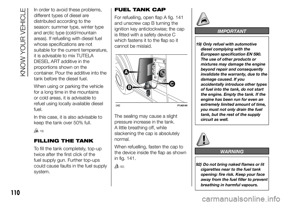
For refuelling, open flap A fig. 141
and unscrew cap B turning the
ignition key anticlockwise; the cap
is fitted with a safety device C
which fastens it to the flap so it
cannot be mislaid.
The sealing may cause a slight
pressure increase in the tank.
A little breathing off, while
slackening the cap is absolutely
normal.
When refuelling, fasten the cap to
the device inside the flap as shown
in fig. 141.
92)
IMPORTANT
19) Only refuel with automotive
diesel complying with the
European specification EN 590.
The use of other products or
mixtures may damage the engine
beyond repair and consequently
invalidate the warranty, due to the
damage caused. If you
accidentally introduce other types
of fuel into the tank, do not start
the engine. Empty the tank. If the
engine has been run for even an
extremely limited amount of time,
you must not only drain the fuel
tank, but the rest of the supply
circuit as well.
WARNING
92) Do not bring naked flames or lit
cigarettes near to the fuel tank
opening: fire risk. Keep your face
away from the fuel filler to prevent
breathing in harmful vapours.
141F1A0144
110
KNOW YOUR VEHICLE
Page 123 of 367
ENGINE OIL LEVEL
GAUGE
(for versions/markets, where
provided)
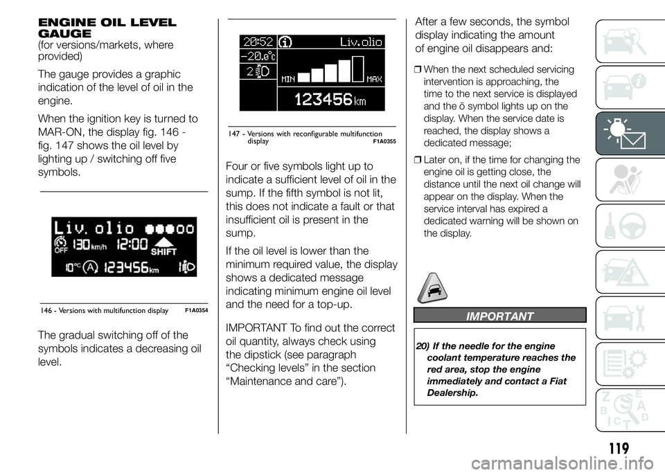
The gauge provides a graphic
indication of the level of oil in the
engine.
When the ignition key is turned to
MAR-ON, the display fig. 146 -
fig. 147 shows the oil level by
lighting up / switching off five
symbols.
The gradual switching off of the
symbols indicates a decreasing oil
level.Four or five symbols light up to
indicate a sufficient level of oil in the
sump. If the fifth symbol is not lit,
this does not indicate a fault or that
insufficient oil is present in the
sump.
If the oil level is lower than the
minimum required value, the display
shows a dedicated message
indicating minimum engine oil level
and the need for a top-up.
IMPORTANT To find out the correct
oil quantity, always check using
the dipstick (see paragraph
“Checking levels” in the section
“Maintenance and care”).After a few seconds, the symbol
display indicating the amount
of engine oil disappears and:
❒When the next scheduled servicing
intervention is approaching, the
time to the next service is displayed
and the õ symbol lights up on the
display. When the service date is
reached, the display shows a
dedicated message;
❒Later on, if the time for changing the
engine oil is getting close, the
distance until the next oil change will
appear on the display. When the
service interval has expired a
dedicated warning will be shown on
the display.
IMPORTANT
20) If the needle for the engine
coolant temperature reaches the
red area, stop the engine
immediately and contact a Fiat
Dealership.
146 - Versions with multifunction displayF1A0354
Liv.olio
MAX MIN
147 - Versions with reconfigurable multifunctionF1A0355
119
display
Page 132 of 367
– briefly press button MODE to go
back to the menu screen or press
the button for longer to go back
to the standard screen.
NoteThe "Scheduled Servicing Plan"
requires the vehicle to be serviced every
48,000 km (or 30,000 mi). This
indication will appear automatically, with
the key at MAR-ON, starting from
2,000 km (or 1,240 mi) and will be
displayed every 200 km (or 124 mi). Oil
change notification messages are
displayed in the same way. Use the
andbuttons to alternate
between displaying scheduled servicing
and engine oil change information.
Below 200 km servicing indications are
more frequent. The display will be in
km or mi depending on the
measurement unit settings. When the
next scheduled service is approaching,
the word “Service” will appear on the
display, followed by the number of
kilometres or miles left, when the key is
turned to MAR-ON. Contact a Fiat
Dealership to carry out any service
operation in the "Scheduled servicing
plan" and to reset the display.NoteWhen an oil change is nearly due
and the ignition key is turned to
MAR-ON, the display will show a
dedicated message. Engine
performance will decrease still driving in
these conditions. When the change is
due, the dedicated message will
reappear on the display together with
the activation of both the
and
warning lights. Contact a
Fiat Dealership.
Activating/
deactivating front
passenger side
airbags and side
bags for chest
protection
(Passenger airbag)
(for versions/markets, where
provided)
This function allows the passenger
side airbag to be activated/
deactivated.
Proceed as follows:
❒press the MODE button and, after
the message "Bag pass: Off" (to
deactivate) or "Bag pass: On" (to
activate) is displayed by pressing the
andbuttons, press the
MODE button again;
❒the confirmation request message
will appear on the display;❒by pressing the
or
buttons, select (Yes) (to confirm
activation/deactivation) or (No) (to
cancel);
❒press the MODE button briefly and a
message confirming the selection will
be displayed, then you will return to
the menu screen, or hold the button
down to return to the standard
screen without storing.
Daytime running lights
(DRL)
(for versions/markets, where
provided)
With this function is possible to turn
the daytime running lights on and
off.
Proceed as follows to activate or
deactivate this function:
❒briefly press the MODE button. The
display shows a submenu;
❒briefly press the MODE button. "On"
or "Off" flash on the display,
according to what has been
previously set;
❒press
orto make your
choice;
128
KNOWING THE INSTRUMENT PANEL
Page 133 of 367
❒briefly press the MODE button to
return to the submenu screen or hold
the button down to return to the
main menu screen without storing;
❒press the MODE button again to
return to the standard screen or
to the main menu according to the
menu items where you are in.
Automatic main beam
headlights
(for versions/markets, where
provided)
This function activates/deactivates
the automatic headlights.
Proceed as follows to activate or
deactivate this function:
❒briefly press the MODE button. The
display shows a submenu;
❒briefly press the MODE button. "On"
or "Off" flash on the display,
according to what has been
previously set;
❒press
orto make your
choice;
❒briefly press the MODE button to
return to the submenu screen or hold
the button down to return to the
main menu screen without storing;
❒press the MODE button again to
return to the standard screen or
to the main menu according to the
menu items where you are in.
Exit Menu
This is the last function that closes
the cycle of settings listed in the
menu screen.
Pressing the MODE button briefly
will return the display to the
standard screen without storing.
Press button
to return to the
first menu item (Speed Beep).
TRIP COMPUTER
IN BRIEF
The Trip computer is used to
display information on vehicle
operation when the ignition key is
turned to MAR-ON. This function
allows you to define two separate
trips, called "Trip A" and "Trip
B", for monitoring the "complete
mission" (journey) of the vehicle in
a reciprocally independent
manner. Both functions can be
reset (reset means start of a new
journey).
“Trip A” is used to display the
figures relating to:
❒Outside temperature
❒Range
❒Distance travelled A
❒Average consumption A
❒Instant fuel consumption
❒Average speed A
❒Trip time A (driving time).
❒Reset Trip A
129
Page 134 of 367
"Trip B", available on multifunction
display only, is used to display
the values relating to:
❒Distance travelled B
❒Average consumption B
❒Average speed B
❒Trip time B (driving time).
21)
Values displayed
Outside temperature
Indicates the temperature outside
the vehicle passenger
compartment.
Range (for versions/markets, where
provided)
This indicates the distance that can
still be travelled with the fuel in the
tank, assuming that driving style
remains unvaried. The display will
show the reading '-----' when
the following events take place:
❒range value lower than 50 km (or 30
mi)
❒vehicle is left parked with the engine
running for a long time.
IMPORTANT The range can be
affected by several factors: driving
style (see paragraph “Driving style”
in the “Starting and driving”
section), type of route (motorway,
towns and cities, mountain roads,
etc…), usage conditions (load,
tyre pressures, etc…). Trip planning
must therefore take the above
into account.
Distance travelled
This value shows the distance
covered from the start of the new
journey.
Average consumption (for
versions/markets, where provided)
This value shows the approximate
average fuel consumption from
the start of the new journey.
Instant consumption (for versions/
markets where provided)
This value shows the fuel
consumption. The value is
constantly updated. The display will
show “----”ifthecarisparked
with the engine running.Average speed
This value shows the car's average
speed based on the overall time
elapsed since the start of the new
journey.
Trip time
Time elapsed since the start of the
new journey.
IMPORTANT If there is no
information, the Trip computer
displays "----" in place of the value.
When normal operating conditions
are restored, the counting of the
various values is resumed, without
either zeroing the values displayed
prior to the problem, or starting a
new mission.
TRIP control button
The TRIP button is located on the
right stalk fig. 151. With the ignition
key turned to MAR-ON, this button
allows you to view the previously
described values and also zero
them to begin a new journey:
❒brief press to access the various
values displays;
130
KNOWING THE INSTRUMENT PANEL