dashboard FIAT DUCATO BASE CAMPER 2015 Owner handbook (in English)
[x] Cancel search | Manufacturer: FIAT, Model Year: 2015, Model line: DUCATO BASE CAMPER, Model: FIAT DUCATO BASE CAMPER 2015Pages: 367, PDF Size: 19.73 MB
Page 11 of 367
.
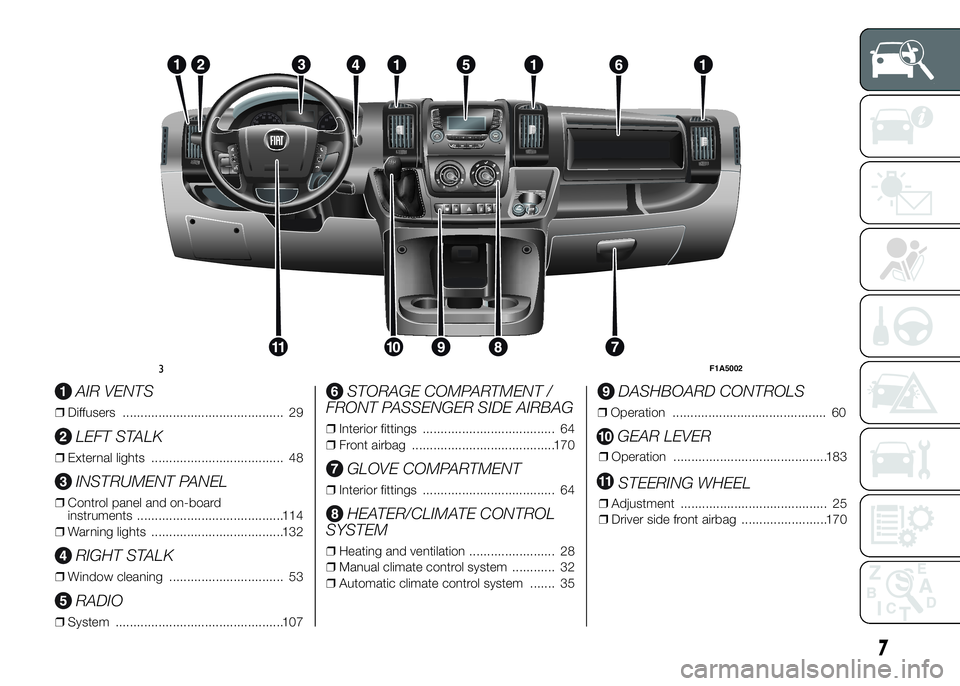
AIR VENTS
❒Diffusers ............................................. 29
LEFT STALK
❒External lights ..................................... 48
INSTRUMENT PANEL
❒Control panel and on-board
instruments .........................................114
❒Warning lights .....................................132
RIGHT STALK
❒Window cleaning ................................ 53
RADIO
❒System ...............................................107
STORAGE COMPARTMENT /
FRONT PASSENGER SIDE AIRBAG
❒Interior fittings ..................................... 64
❒Front airbag ........................................170
GLOVE COMPARTMENT
❒Interior fittings ..................................... 64
HEATER/CLIMATE CONTROL
SYSTEM
❒Heating and ventilation ........................ 28
❒Manual climate control system ............ 32
❒Automatic climate control system ....... 35
DASHBOARD CONTROLS
❒Operation ........................................... 60
GEAR LEVER
❒Operation ...........................................183
STEERING WHEEL
❒Adjustment ......................................... 25
❒Driver side front airbag ........................170
RADIO
MEDIA
PHONEINFO
A-B-C
MENU
123 4 56
3F1A5002
7
Page 16 of 367
❒opening and closing of the fuel tank
cap.
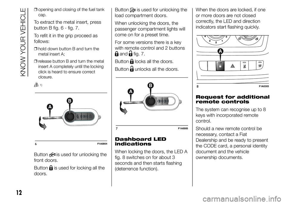
To extract the metal insert, press
button B fig. 6 - fig. 7.
To refit it in the grip proceed as
follows:
❒hold down button B and turn the
metal insert A;
❒release button B and turn the metal
insert A completely until the locking
click is heard to ensure correct
closure.
1)
Buttonis used for unlocking the
front doors.
Button
is used for locking all the
doors.Button
is used for unlocking the
load compartment doors.
When unlocking the doors, the
passenger compartment lights will
come on for a preset time.
For some versions there is a key
with remote control and 2 buttons
andfig. 7.
Button
locks all the doors.
Button
unlocks all the doors.
Dashboard LED
indications
When locking the doors, the LED A
fig. 8 switches on for about 3
seconds and then starts flashing
(deterrence function).When the doors are locked, if one
or more doors are not closed
correctly, the LED and direction
indicators start flashing quickly.
Request for additional
remote controls
The system can recognise up to 8
keys with incorporated remote
control.
Should a new remote control be
necessary, contact a Fiat
Dealership and be ready to present
the CODE card, a personal identity
document and the vehicle
ownership documents.
6F1A0004
7F1A0005
8F1A0303
12
KNOW YOUR VEHICLE
Page 17 of 367
Changing battery -
key with remote
control
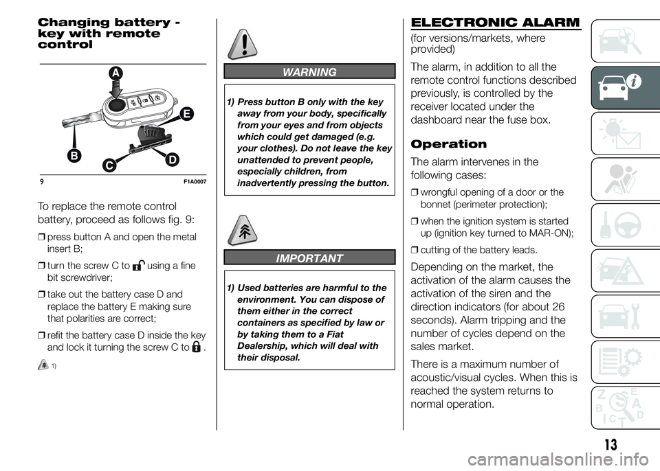
To replace the remote control
battery, proceed as follows fig. 9:
❒press button A and open the metal
insert B;
❒turn the screw C to
using a fine
bit screwdriver;
❒take out the battery case D and
replace the battery E making sure
that polarities are correct;
❒refit the battery case D inside the key
and lock it turning the screw C to
.
1)
WARNING
1) Press button B only with the key
away from your body, specifically
from your eyes and from objects
which could get damaged (e.g.
your clothes). Do not leave the key
unattended to prevent people,
especially children, from
inadvertently pressing the button.
IMPORTANT
1) Used batteries are harmful to the
environment. You can dispose of
them either in the correct
containers as specified by law or
by taking them to a Fiat
Dealership, which will deal with
their disposal.
ELECTRONIC ALARM
(for versions/markets, where
provided)
The alarm, in addition to all the
remote control functions described
previously, is controlled by the
receiver located under the
dashboard near the fuse box.
Operation
The alarm intervenes in the
following cases:
❒wrongful opening of a door or the
bonnet (perimeter protection);
❒when the ignition system is started
up (ignition key turned to MAR-ON);
❒cutting of the battery leads.
Depending on the market, the
activation of the alarm causes the
activation of the siren and the
direction indicators (for about 26
seconds). Alarm tripping and the
number of cycles depend on the
sales market.
There is a maximum number of
acoustic/visual cycles. When this is
reached the system returns to
normal operation.
9F1A0007
13
Page 34 of 367
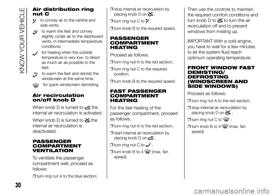
Air distribution ring
nut C
to convey air to the central and
side vents;
to warm the feet and convey
slightly cooler air to the dashboard
vents, in intermediate temperature
conditions;
for heating when the outside
temperature is very low: to direct
as much air as possible to the
feet;
to warm the feet and demist the
windscreen at the same time;
for quick windscreen demisting.
Air recirculation
on/off knob D
When knob D is turned to
the
internal air recirculation is activated.
When knob D is turned to
the
internal air recirculation is
deactivated.
PASSENGER
COMPARTMENT
VENTILATION
To ventilate the passenger
compartment well, proceed as
follows:
❒turn ring nut A to the blue section;❒stop internal air recirculation by
placing knob D on
;
❒turn ring nut C to
;
❒turn knob B to the required speed.
PASSENGER
COMPARTMENT
HEATING
Proceed as follows:
❒turn ring nut A to the red section;
❒turn ring nut C to the required
position;
❒turn knob B to the required speed.
FAST PASSENGER
COMPARTMENT
HEATING
For the fast heating of the
passenger compartment, proceed
as follows:
❒turn ring nut A to the red section;
❒start internal air recirculation by
placing knob D on
;
❒turn ring nut C to
;
❒turn knob B to 4
(max. fan
speed).
Then use the controls to maintain
the required comfort conditions and
turn knob D to
to turn the air
recirculation off and to prevent
windows from misting up.
IMPORTANT With a cold engine,
you have to wait for a few minutes
to let the system fluid reach
optimum operating temperature.
FRONT WINDOW FAST
DEMISTING/
DEFROSTING
(WINDSCREEN AND
SIDE WINDOWS)
Proceed as follows:
❒turn ring nut A to the red section;
❒stop internal air recirculation by
placing knob D on
;
❒turn ring nut C to
;
❒turn knob B to 4
(max. fan
speed).
30
KNOW YOUR VEHICLE
Page 36 of 367
Do not use the air recirculation
function on rainy/cold days as it
would considerably increase the
possibility of the windows misting
inside.
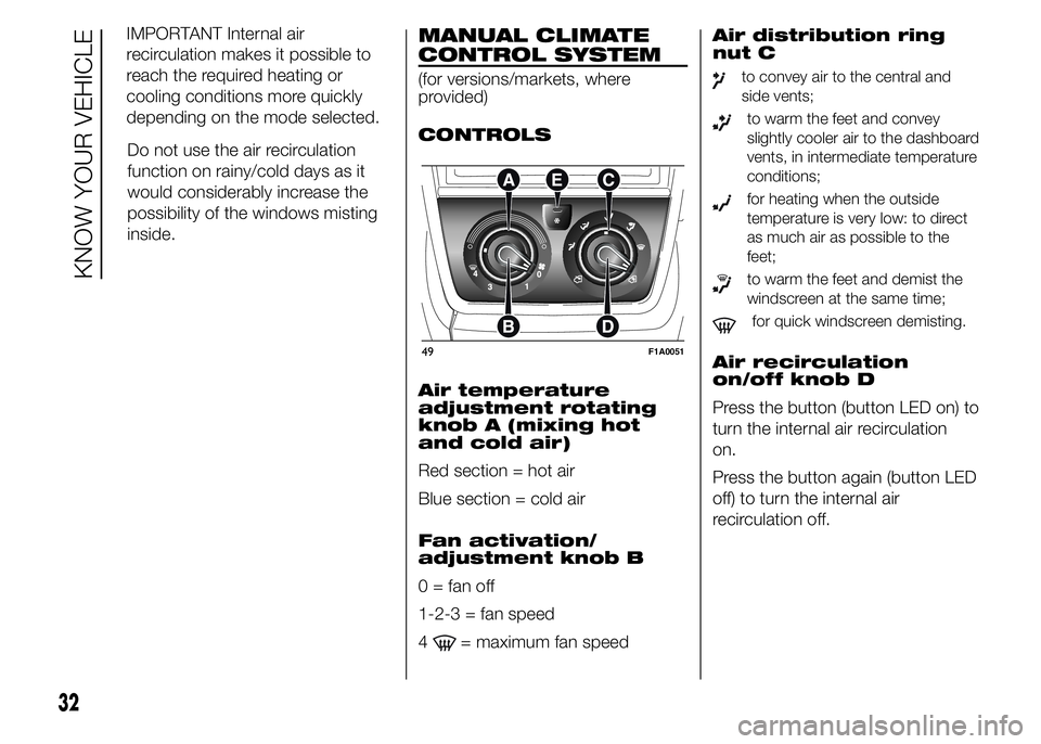
MANUAL CLIMATE
CONTROL SYSTEM
(for versions/markets, where
provided)
CONTROLS
Air temperature
adjustment rotating
knob A (mixing hot
and cold air)
Red section = hot air
Blue section = cold air
Fan activation/
adjustment knob B
0 = fan off
1-2-3 = fan speed
4
= maximum fan speedAir distribution ring
nut C
to convey air to the central and
side vents;
to warm the feet and convey
slightly cooler air to the dashboard
vents, in intermediate temperature
conditions;
for heating when the outside
temperature is very low: to direct
as much air as possible to the
feet;
to warm the feet and demist the
windscreen at the same time;
for quick windscreen demisting.
Air recirculation
on/off knob D
Press the button (button LED on) to
turn the internal air recirculation
on.
Press the button again (button LED
off) to turn the internal air
recirculation off.49F1A0051
32
KNOW YOUR VEHICLE
IMPORTANT Internal air
recirculation makes it possible to
reach the required heating or
cooling conditions more quickly
depending on the mode selected.
Page 42 of 367
In particular, if the heating fluid is
not sufficiently hot, the maximum
fan speed does not come on
straight away in order to limit the
intake of insufficiently hot air to the
passenger compartment.
All manual settings will be allowed
when this function is on.
To switch the function off, simply
turn the temperature knob
anticlockwise and set the required
temperature.
❒LO function (maximum cooling):
select by turning the temperature
knob anticlockwise beyond the
minimum value (16°C).
This function may be used to cool
down the passenger compartment
by exploiting the system's potential
to the full. In this event, the system
stops controlling the temperature
automatically and sets the air
mixing to maximum cooling. The air
speed and distribution are fixed.
All manual settings will be allowed
when this function is on.
To switch the function off, simply
turn the temperature knob
anticlockwise and set the required
temperature.Air distribution
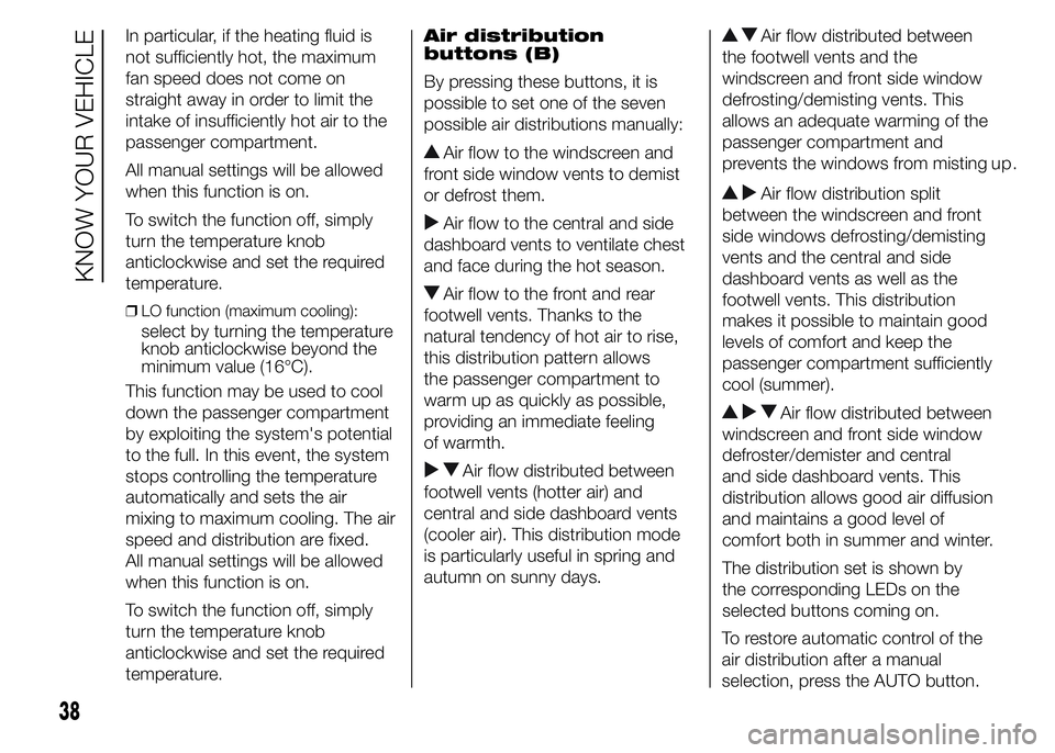
buttons (B)
By pressing these buttons, it is
possible to set one of the seven
possible air distributions manually:
Air flow to the windscreen and
front side window vents to demist
or defrost them.
Air flow to the central and side
dashboard vents to ventilate chest
and face during the hot season.
Air flow to the front and rear
footwell vents. Thanks to the
natural tendency of hot air to rise,
this distribution pattern allows
the passenger compartment to
warm up as quickly as possible,
providing an immediate feeling
of warmth.
Air flow distributed between
footwell vents (hotter air) and
central and side dashboard vents
(cooler air). This distribution mode
is particularly useful in spring and
autumn on sunny days.
Air flow distributed between
the footwell vents and the
windscreen and front side window
defrosting/demisting vents. This
allows an adequate warming of the
passenger compartment and
prevents the windows from misting up.
Air flow distribution split
between the windscreen and front
side windows defrosting/demisting
vents and the central and side
dashboard vents as well as the
footwell vents. This distribution
makes it possible to maintain good
levels of comfort and keep the
passenger compartment sufficiently
cool (summer).
Air flow distributed between
windscreen and front side window
defroster/demister and central
and side dashboard vents. This
distribution allows good air diffusion
and maintains a good level of
comfort both in summer and winter.
The distribution set is shown by
the corresponding LEDs on the
selected buttons coming on.
38
KNOW YOUR VEHICLE
To restore automatic control of the
air distribution after a manual
selection, press the AUTO button.
Page 68 of 367
INTERIOR FITTINGS
UPPER STORAGE
COMPARTMENT -
REFRIGERATED
COMPARTMENT
(for versions/markets, where
provided)
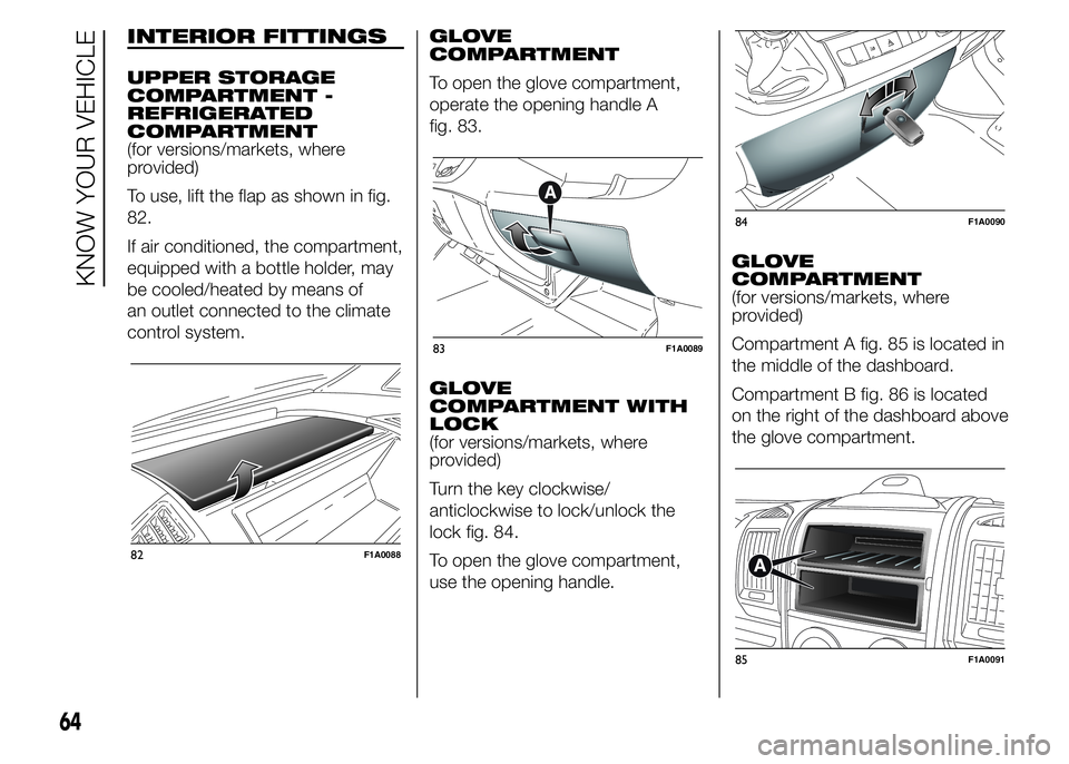
To use, lift the flap as shown in fig.
82.
If air conditioned, the compartment,
equipped with a bottle holder, may
be cooled/heated by means of
an outlet connected to the climate
control system.GLOVE
COMPARTMENT
To open the glove compartment,
operate the opening handle A
fig. 83.
GLOVE
COMPARTMENT WITH
LOCK
(for versions/markets, where
provided)
Turn the key clockwise/
anticlockwise to lock/unlock the
lock fig. 84.
To open the glove compartment,
use the opening handle.GLOVE
COMPARTMENT
(for versions/markets, where
provided)
Compartment A fig. 85 is located in
the middle of the dashboard.
Compartment B fig. 86 is located
on the right of the dashboard above
the glove compartment.
82F1A0088
83F1A0089
84F1A0090
85F1A0091
64
KNOW YOUR VEHICLE
Page 69 of 367
CUP HOLDER - CAN
HOLDER - BOTTLE
HOLDER ON
DASHBOARD
(for versions/markets, where
provided)
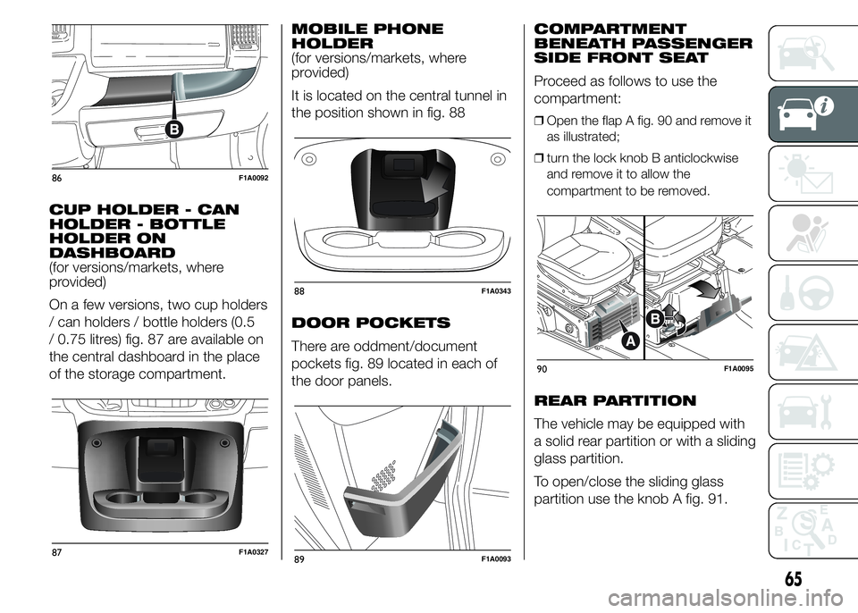
On a few versions, two cup holders
/ can holders / bottle holders (0.5
/ 0.75 litres) fig. 87 are available on
the central dashboard in the place
of the storage compartment.MOBILE PHONE
HOLDER
(for versions/markets, where
provided)
It is located on the central tunnel in
the position shown in fig. 88
DOOR POCKETS
There are oddment/document
pockets fig. 89 located in each of
the door panels.COMPARTMENT
BENEATH PASSENGER
SIDE FRONT SEAT
Proceed as follows to use the
compartment:
❒Open the flap A fig. 90 and remove it
as illustrated;
❒turn the lock knob B anticlockwise
and remove it to allow the
compartment to be removed.
REAR PARTITION
The vehicle may be equipped with
a solid rear partition or with a sliding
glass partition.
To open/close the sliding glass
partition use the knob A fig. 91.
86F1A0092
87F1A0327
88F1A0343
89F1A0093
90F1A0095
65
Page 70 of 367
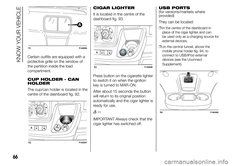
Certain outfits are equipped with a
protective grille on the window of
the partition inside the load
compartment.
CUP HOLDER - CAN
HOLDER
The cup/can holder is located in the
centre of the dashboard fig. 92.CIGAR LIGHTER
It is located in the centre of the
dashboard fig. 93.
Press button on the cigarette lighter
to switch it on when the ignition
key is turned to MAR-ON.
After about 15 seconds the button
will return to its original position
automatically and the cigar lighter is
ready for use.
31)
IMPORTANT Always check that the
cigar lighter has switched off.USB PORTS
(for versions/markets where
provided)
They can be located:
❒in the centre of the dashboard in
place of the cigar lighter and can
be used only as a charging source for
external devices;
❒on the central tunnel, above the
mobile phone holder fig. 94, to
connect to USB/iPod external
devices (see the Uconnect
Supplement).
91F1A0096
92F1A0307
93F1A0309
66
KNOW YOUR VEHICLE
94F1A0395
Page 71 of 367
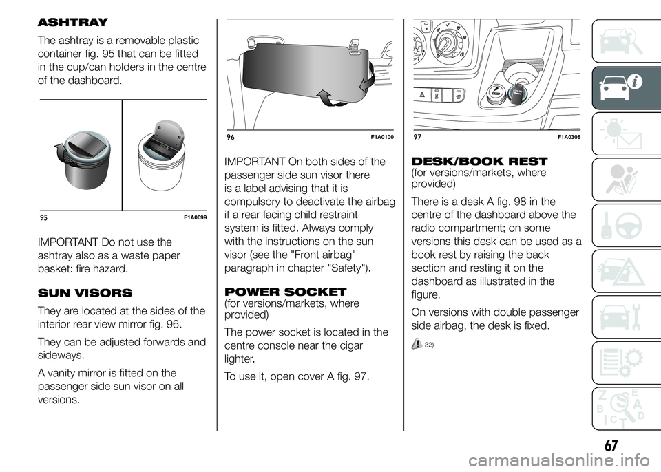
ASHTRAY
The ashtray is a removable plastic
container fig. 95 that can be fitted
in the cup/can holders in the centre
of the dashboard.
IMPORTANT Do not use the
ashtray also as a waste paper
basket: fire hazard.
SUN VISORS
They are located at the sides of the
interior rear view mirror fig. 96.
They can be adjusted forwards and
sideways.
A vanity mirror is fitted on the
passenger side sun visor on all
versions.IMPORTANT On both sides of the
passenger side sun visor there
is a label advising that it is
compulsory to deactivate the airbag
if a rear facing child restraint
system is fitted. Always comply
with the instructions on the sun
visor (see the "Front airbag"
paragraph in chapter "Safety").
POWER SOCKET
(for versions/markets, where
provided)
The power socket is located in the
centre console near the cigar
lighter.
To use it, open cover A fig. 97.DESK/BOOK REST
(for versions/markets, where
provided)
There is a desk A fig. 98 in the
centre of the dashboard above the
radio compartment; on some
versions this desk can be used as a
book rest by raising the back
section and resting it on the
dashboard as illustrated in the
figure.
On versions with double passenger
side airbag, the desk is fixed.
32)
95F1A0099
96F1A010097F1A0308
67