key battery FIAT DUCATO BASE CAMPER 2015 Owner handbook (in English)
[x] Cancel search | Manufacturer: FIAT, Model Year: 2015, Model line: DUCATO BASE CAMPER, Model: FIAT DUCATO BASE CAMPER 2015Pages: 367, PDF Size: 19.73 MB
Page 6 of 367
READ THIS CAREFULLY
REFUELLING
Only refuel with automotive diesel conforming to the European specification EN590. The use of other products or mixtures may damage the
engine beyond repair and consequently invalidate the warranty, due to the damage caused.
STARTING THE ENGINE
Make sure that the handbrake is engaged; set the gear lever to neutral; fully depress the clutch pedal without pressing the accelerator, then
turn the ignition key to MAR-ON and wait for the warning lightsandto switch off; turn the ignition key to AVV and release it as
soon as the engine has started.
PARKING ON FLAMMABLE MATERIAL
The catalytic converter develops high temperatures during operation. Do not park on grass, dry leaves, pine needles or other flammable
material: fire hazard.
RESPECTING THE ENVIRONMENT
The vehicle is fitted with a system that allows continuous diagnosis of the emission-related components in order to help protect the
environment.
ELECTRICAL ACCESSORIES
If, after buying the vehicle, you decide to add electrical accessories (with the risk of gradually draining the battery), visit a Fiat Dealership. They
can calculate the overall electrical requirement and check that the vehicle's electrical system can support the required load.
SCHEDULED SERVICING
Correct maintenance enables the vehicle to perfectly maintain performance and safety characteristics, its environmental friendliness and low
running costs over time.
THE OWNER HANDBOOK CONTAINS
... important information, advice and warnings for correct use, driving safety and maintenance of your vehicle over time. Special attention
must be paid to the symbols(safety of persons)(environmental protection)(vehicle integrity).
Page 17 of 367
Changing battery -
key with remote
control
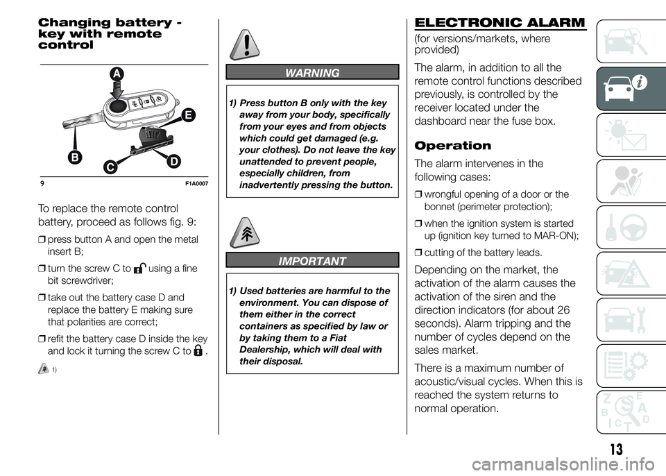
To replace the remote control
battery, proceed as follows fig. 9:
❒press button A and open the metal
insert B;
❒turn the screw C to
using a fine
bit screwdriver;
❒take out the battery case D and
replace the battery E making sure
that polarities are correct;
❒refit the battery case D inside the key
and lock it turning the screw C to
.
1)
WARNING
1) Press button B only with the key
away from your body, specifically
from your eyes and from objects
which could get damaged (e.g.
your clothes). Do not leave the key
unattended to prevent people,
especially children, from
inadvertently pressing the button.
IMPORTANT
1) Used batteries are harmful to the
environment. You can dispose of
them either in the correct
containers as specified by law or
by taking them to a Fiat
Dealership, which will deal with
their disposal.
ELECTRONIC ALARM
(for versions/markets, where
provided)
The alarm, in addition to all the
remote control functions described
previously, is controlled by the
receiver located under the
dashboard near the fuse box.
Operation
The alarm intervenes in the
following cases:
❒wrongful opening of a door or the
bonnet (perimeter protection);
❒when the ignition system is started
up (ignition key turned to MAR-ON);
❒cutting of the battery leads.
Depending on the market, the
activation of the alarm causes the
activation of the siren and the
direction indicators (for about 26
seconds). Alarm tripping and the
number of cycles depend on the
sales market.
There is a maximum number of
acoustic/visual cycles. When this is
reached the system returns to
normal operation.
9F1A0007
13
Page 63 of 367
ROOF LIGHTS
FRONT ROOF LIGHT
WITH SPOT LIGHTS
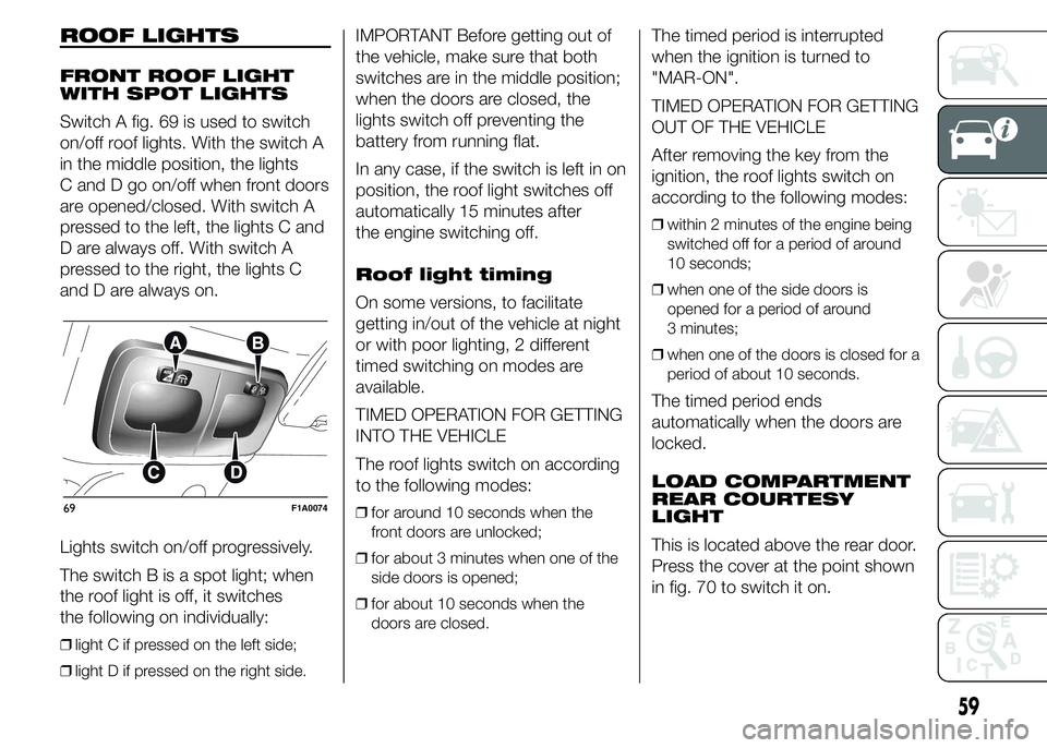
Switch A fig. 69 is used to switch
on/off roof lights. With the switch A
in the middle position, the lights
C and D go on/off when front doors
are opened/closed. With switch A
pressed to the left, the lights C and
D are always off. With switch A
pressed to the right, the lights C
and D are always on.
Lights switch on/off progressively.
The switch B is a spot light; when
the roof light is off, it switches
the following on individually:
❒light C if pressed on the left side;
❒light D if pressed on the right side.
IMPORTANT Before getting out of
the vehicle, make sure that both
switches are in the middle position;
when the doors are closed, the
lights switch off preventing the
battery from running flat.
In any case, if the switch is left in on
position, the roof light switches off
automatically 15 minutes after
the engine switching off.
Roof light timing
On some versions, to facilitate
getting in/out of the vehicle at night
or with poor lighting, 2 different
timed switching on modes are
available.
TIMED OPERATION FOR GETTING
INTO THE VEHICLE
The roof lights switch on according
to the following modes:
❒for around 10 seconds when the
front doors are unlocked;
❒for about 3 minutes when one of the
side doors is opened;
❒for about 10 seconds when the
doors are closed.
The timed period is interrupted
when the ignition is turned to
"MAR-ON".
TIMED OPERATION FOR GETTING
OUT OF THE VEHICLE
After removing the key from the
ignition, the roof lights switch on
according to the following modes:
❒within 2 minutes of the engine being
switched off for a period of around
10 seconds;
❒when one of the side doors is
opened for a period of around
3 minutes;
❒when one of the doors is closed for a
period of about 10 seconds.
The timed period ends
automatically when the doors are
locked.
LOAD COMPARTMENT
REAR COURTESY
LIGHT
This is located above the rear door.
Press the cover at the point shown
in fig. 70 to switch it on.
69F1A0074
59
Page 64 of 367
LOAD COMPARTMENT
SIDE COURTESY
LIGHT
(for versions/markets, where
provided)
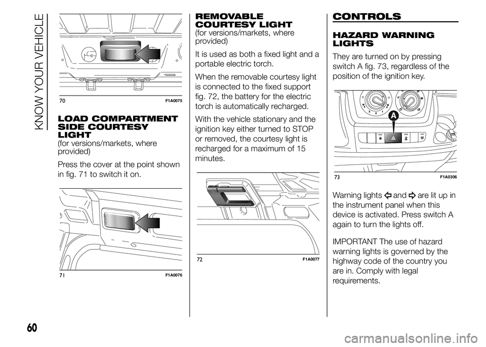
Press the cover at the point shown
in fig. 71 to switch it on.REMOVABLE
COURTESY LIGHT
(for versions/markets, where
provided)
It is used as both a fixed light and a
portable electric torch.
When the removable courtesy light
is connected to the fixed support
fig. 72, the battery for the electric
torch is automatically recharged.
With the vehicle stationary and the
ignition key either turned to STOP
or removed, the courtesy light is
recharged for a maximum of 15
minutes.
CONTROLS
HAZARD WARNING
LIGHTS
They are turned on by pressing
switch A fig. 73, regardless of the
position of the ignition key.
Warning lights
andare lit up in
the instrument panel when this
device is activated. Press switch A
again to turn the lights off.
IMPORTANT The use of hazard
warning lights is governed by the
highway code of the country you
are in. Comply with legal
requirements.
70F1A0075
71F1A0076
72F1A0077
73F1A0306
60
KNOW YOUR VEHICLE
Page 66 of 367
BATTERY
DISCONNECTION
FUNCTION
(DISCONNECTOR)
(for versions/markets, where
provided)
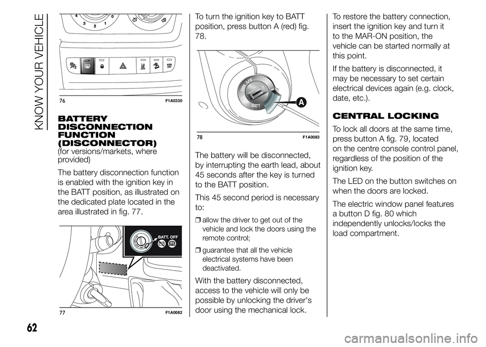
The battery disconnection function
is enabled with the ignition key in
the BATT position, as illustrated on
the dedicated plate located in the
area illustrated in fig. 77.To turn the ignition key to BATT
position, press button A (red) fig.
78.
The battery will be disconnected,
by interrupting the earth lead, about
45 seconds after the key is turned
to the BATT position.
This 45 second period is necessary
to:
❒allow the driver to get out of the
vehicle and lock the doors using the
remote control;
❒guarantee that all the vehicle
electrical systems have been
deactivated.
With the battery disconnected,
access to the vehicle will only be
possible by unlocking the driver's
door using the mechanical lock.To restore the battery connection,
insert the ignition key and turn it
to the MAR-ON position, the
vehicle can be started normally at
this point.
If the battery is disconnected, it
may be necessary to set certain
electrical devices again (e.g. clock,
date, etc.).
CENTRAL LOCKING
To lock all doors at the same time,
press button A fig. 79, located
on the centre console control panel,
regardless of the position of the
ignition key.
The LED on the button switches on
when the doors are locked.
The electric window panel features
a button D fig. 80 which
independently unlocks/locks the
load compartment.
76F1A0330
77F1A0082
78F1A0083
62
KNOW YOUR VEHICLE
Page 67 of 367
FUEL CUT-OFF
SWITCH
The vehicle is fitted with a safety
switch that, in the event of a crash,
comes into operation by cutting
off the fuel supply and turning
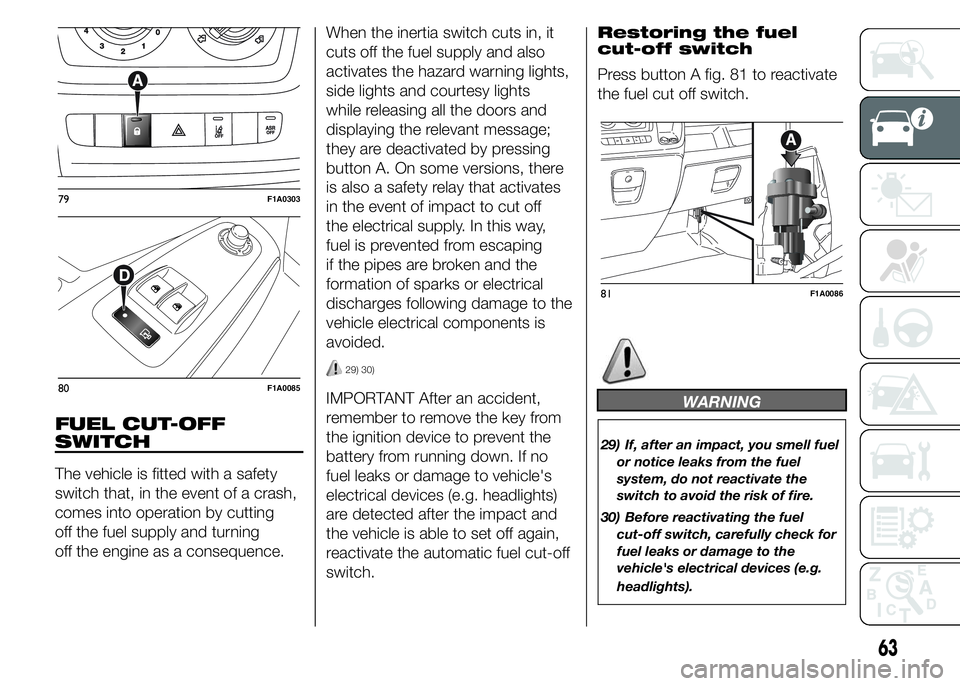
off the engine as a consequence.When the inertia switch cuts in, it
cuts off the fuel supply and also
activates the hazard warning lights,
side lights and courtesy lights
while releasing all the doors and
displaying the relevant message;
they are deactivated by pressing
button A. On some versions, there
is also a safety relay that activates
in the event of impact to cut off
the electrical supply. In this way,
fuel is prevented from escaping
if the pipes are broken and the
formation of sparks or electrical
discharges following damage to the
vehicle electrical components is
avoided.
29) 30)
IMPORTANT After an accident,
remember to remove the key from
the ignition device to prevent the
battery from running down. If no
fuel leaks or damage to vehicle's
electrical devices (e.g. headlights)
are detected after the impact and
the vehicle is able to set off again,
reactivate the automatic fuel cut-off
switch.Restoring the fuel
cut-off switch
Press button A fig. 81 to reactivate
the fuel cut off switch.WARNING
29) If, after an impact, you smell fuel
or notice leaks from the fuel
system, do not reactivate the
switch to avoid the risk of fire.
30) Before reactivating the fuel
cut-off switch, carefully check for
fuel leaks or damage to the
vehicle's electrical devices (e.g.
headlights).
79F1A0303
80F1A0085
81F1A0086
63
Page 76 of 367
DOORS
DOOR CENTRAL
LOCKING/UNLOCKING
Locking doors from
the outside
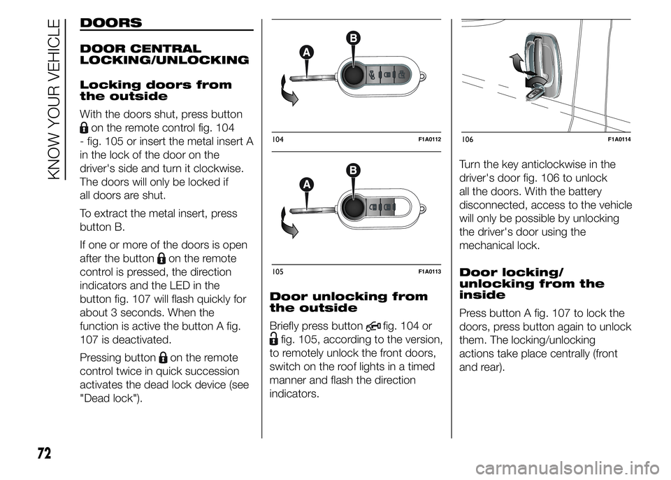
With the doors shut, press button
on the remote control fig. 104
- fig. 105 or insert the metal insert A
in the lock of the door on the
driver's side and turn it clockwise.
The doors will only be locked if
all doors are shut.
To extract the metal insert, press
button B.
If one or more of the doors is open
after the button
on the remote
control is pressed, the direction
indicators and the LED in the
button fig. 107 will flash quickly for
about 3 seconds. When the
function is active the button A fig.
107 is deactivated.
Pressing button
on the remote
control twice in quick succession
activates the dead lock device (see
"Dead lock").Door unlocking from
the outside
Briefly press button
fig. 104 or
fig. 105, according to the version,
to remotely unlock the front doors,
switch on the roof lights in a timed
manner and flash the direction
indicators.Turn the key anticlockwise in the
driver's door fig. 106 to unlock
all the doors. With the battery
disconnected, access to the vehicle
will only be possible by unlocking
the driver's door using the
mechanical lock.
Door locking/
unlocking from the
inside
Press button A fig. 107 to lock the
doors, press button again to unlock
them. The locking/unlocking
actions take place centrally (front
and rear).
104F1A0112
105F1A0113
106F1A0114
72
KNOW YOUR VEHICLE
Page 81 of 367
WARNING
34) Once the dead lock system is
engaged it is impossible to open
the doors from inside the vehicle.
Therefore, before engaging the
system check that there is no one
left inside. If the remote control
battery is flat, the system can be
disengaged only by inserting
the key metal insert in either of
the door locks as described
previously: in this case the device
remains active only for the rear
doors.
35) Before leaving the vehicle
parked with sliding doors open,
always check that the latch is
engaged.
36) Do not move the vehicle with
side doors open.37) Before setting off after parking
or before moving the vehicle in
any way, ensure that the
footboard is fully stowed away. As
the movement of the platform is
linked to that of the sliding side
door, thewarning light in the
instrument panel comes on if it is
not fully retracted in the same
way as when the rear doors are
not shut.
38) This spring loaded system has
activation forces that were
designed for optimum comfort.
Accidental knocks or a strong
gust of wind may release the
springs and close the doors
spontaneously.
39) With the doors opened to 180
degrees, no locking system is
effective. Do not use this opening
with the vehicle parked on a
gradient or when it is windy.
40) It is forbidden to drive the
vehicle with the footboard open.
41) Do not use the retracted
footboard for getting up or down
the load compartment.42) Make sure that the footboard is
suitably locked by the provided
retaining systems before, after
and during its use. An incomplete
opening or closing might cause
an improper movement of the
footboard with risks arising for the
operator and external users.
43) The footboard lightly projects
from the vehicle even if retracted;
therefore, when rear parking
sensors are provided, their
operating range is lightly reduced.
IMPORTANT
5) The footboard presence may
reduce the ramp approach angles;
it is therefore recommended, in
case of a very steep ramp, to
be very careful in order not to
damage the footboard.
77
Page 109 of 367
❒vehicle in motion (e.g. when driving
on roads with a gradient);
❒stopping the engine through the
Start&Stop system for more than
about three minutes.
❒automatic climate control system for
adjusting the thermal comfort level or
to enable MAX-DEF function.
With a gear engaged, the engine
can be automatically restarted only
by fully depressing the clutch pedal.
NoteIf the engine stops and this is
not desired, due for example to the
clutch pedal being released sharply
with a gear engaged, if the Start&Stop
system is active, the engine can be
restarted by fully depressing the clutch
pedal or by placing the gear lever in
neutral.
NoteIf the clutch is not pressed, when
approx. three minutes have elapsed
since the engine was stopped, the
engine can only be restarted using the
key.
SAFETY FUNCTIONS
In engine cut-out conditions
through the Start&Stop system, if
the driver unfastens his/her seat
belt and opens the driver's door or
the passenger door, the engine
can be restarted only by using the
key. The driver is notified of this
condition by a buzzer, through the
warning light flashing in the
instrument panel and, where
provided, by a message in the
display.
"ENERGY SAVING"
FUNCTION
(for versions/markets, where
provided)
If, after the engine has been
automatically restarted, the driver
does not take any action for a
period of about 3 minutes,
the Start&Stop system will
definitively stop the engine to avoid
fuel consumption. The engine
can only be started using the key in
such cases.
NoteIn any case, it is possible to keep
the engine running by deactivating
the Start&Stop system.
IRREGULAR
OPERATION
In the event of malfunction, the
Start&Stop system is deactivated.
The driver is informed about the
fault through the switching on of the
icon together with a message
on the display. In this case, contact
a Fiat Dealership.
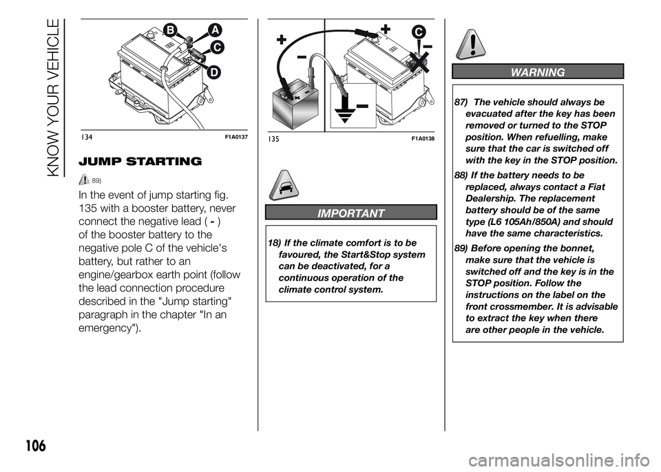
VEHICLE INACTIVITY
In the event of vehicle inactivity,
special attention must be paid to
the disconnection of the battery
power supply. Proceed as follows:
detach connector A fig. 134 (by
pressing button B) from sensor C
for monitoring the status of the
battery installed on the negative
battery pole D. This sensor should
never be disconnected from the
pole except if the battery is
replaced.
87) 88)
IMPORTANT After turning the
ignition key to STOP, wait at least 1
minute before disconnecting the
electrical supply to the battery.
105
Page 110 of 367
JUMP STARTING
89)
In the event of jump starting fig.
135 with a booster battery, never
connect the negative lead (-)
of the booster battery to the
negative pole C of the vehicle's
battery, but rather to an
engine/gearbox earth point (follow
the lead connection procedure
described in the "Jump starting"
paragraph in the chapter "In an
emergency").
IMPORTANT
18) If the climate comfort is to be
favoured, the Start&Stop system
can be deactivated, for a
continuous operation of the
climate control system.
WARNING
87) The vehicle should always be
evacuated after the key has been
removed or turned to the STOP
position. When refuelling, make
sure that the car is switched off
with the key in the STOP position.
88) If the battery needs to be
replaced, always contact a Fiat
Dealership. The replacement
battery should be of the same
type (L6 105Ah/850A) and should
have the same characteristics.
89) Before opening the bonnet,
make sure that the vehicle is
switched off and the key is in the
STOP position. Follow the
instructions on the label on the
front crossmember. It is advisable
to extract the key when there
are other people in the vehicle.
134F1A0137135F1A0138
106
KNOW YOUR VEHICLE