starting FIAT DUCATO BASE CAMPER 2016 Owner handbook (in English)
[x] Cancel search | Manufacturer: FIAT, Model Year: 2016, Model line: DUCATO BASE CAMPER, Model: FIAT DUCATO BASE CAMPER 2016Pages: 387, PDF Size: 20.76 MB
Page 192 of 387
❒lastly, remember that the vehicle’s
dynamic behaviour is affected by
the weight transported: in particular,
the stopping distances are longer,
especially at high speed.
IMPORTANT
36) Each of these must be strictly
observed and MUST NEVER BE
EXCEEDED in any case. In
particular, ensure that you never
exceed the maximum permitted
weights on the front and rear
axles when arranging the load on
the vehicle (particularly if the
vehicle is equipped with a specific
trim level).
WARNING
137) Irregular trajectories and abrupt
braking may cause sudden
movements of the load with
consequent situations of hazard
for the driver and passengers:
before setting off, secure the load
tightly using the appropriate
hooks on the floor and use steel
cables, ropes or chains strong
enough to hold the items to be
secured.
138) If a vehicle is parked on a very
steep gradient or with a side
gradient, opening the rear door or
side door could cause any
unsecured items to emerge
suddenly.
139) If you wish to carry a reserve of
petrol in a can, observe the legal
restrictions and only use a can
that is type-approved and
properly secured to the load
anchorage eyebolts. Anyway, by
doing so, you increase the risk
of fire in the event of an accident
with your vehicle.
SAVING FUEL
Some useful tips are given below for
fuel saving and reducing harmful
emissions of CO2 and other pollutants
(nitrogen oxides, unburnt
hydrocarbons, Particulate Matter (PM),
etc.).
GENERAL
CONSIDERATIONS
The general factors that affect fuel
consumption are listed below.
Vehicle maintenance
Have checks and adjustments carried
out in accordance with the “Scheduled
Servicing Plan”.
Tyres
Check the tyre pressures at least once
every four weeks: if the pressure is
too low, consumption levels increase as
resistance to rolling is higher.
Unnecessary loads
Do not travel with an overloaded
luggage compartment. The weight of
the vehicle (especially when driving
in town) and its geometry greatly affect
fuel consumption and stability.
188
STARTING AND DRIVING
Page 193 of 387
Roof rack/ski rack
Remove the roof rack or the ski rack
from the roof after use. These
accessories decrease aerodynamic
penetration of the vehicle and have a
negative effect on fuel consumption.
When transporting particularly large
objects, use a trailer if possible.
Electric devices
Use electrical devices only for the
amount of time needed. The heated
rear window, additional headlights,
windscreen/rear window wipers and
heater fan need a considerable amount
of energy, therefore increasing fuel
consumption (by up to 25% in
the urban cycle).
Climate control system
Air conditioning leads to higher fuel
consumption (on average up to +20%).
If the temperature outside permits, try
and use the ventilation only.
Devices for
aerodynamic control
The use of non-certified spoilers may
adversely affect air drag and fuel
consumption.DRIVING STYLE
The main driving styles that affect fuel
consumption are listed below.
Cranking
Do not warm up the engine at low or
high revs when the vehicle is stationary;
this causes the engine to warm up
more slowly, thereby increasing fuel
consumption and emissions. It is
therefore advisable to move off
immediately, slowly, avoiding high
speeds: in this way the engine will
warm up more quickly.
Unnecessary actions
Avoid accelerating when stopped at
traffic lights or before switching off the
engine. This action and also double
declutching is absolutely pointless on
modern cars and also increases
consumption and pollution.
Gear selection
As soon as the conditions of the traffic
and road permit, use a higher gear.
Using a low gear for faster acceleration
will increase consumption.
In the same way improper use of a high
gear increases consumption, emissions
and engine wear.Max. speed
Fuel consumption increases
considerably with speed. Maintain a
constant speed, avoiding unnecessary
braking and acceleration, which cost
in terms of both fuel consumption and
emissions.
Acceleration
Accelerating violently will greatly affect
consumption and emissions:
acceleration should be gradual.
USAGE CONDITIONS
The main usage conditions that
negatively affect fuel consumption are
listed below.
Cold starting
Short journeys and frequent cold starts
do not allow the engine to reach
optimum operating temperature.
This results in a significant increase in
consumption levels (from +15 to +30%
on the urban cycle) and emissions.
189
Page 194 of 387
Traffic and road
conditions
Rather high consumption levels are
linked to situations with heavy traffic, for
instance when travelling in queues
with frequent use of the lower gears or
in cities with many traffic lights. Winding
mountain roads and rough road
surfaces also adversely affect
consumption.
Stops in traffic
During prolonged hold-ups (e.g. level
crossings) the engine should be
switched off.TOWING TRAILERS
IMPORTANT
INFORMATION
The vehicle must be provided with a
type-approved tow hook and adequate
electrical system to tow caravans or
trailers. Installation should be carried
out by specialised personnel who
will issue the required papers for
travelling on roads.
Install any specific and/or additional
door mirrors as specified by the
Highway Code.
Remember that when towing a trailer,
steep hills are harder to climb, the
braking spaces increase and overtaking
takes longer depending on the overall
weight.
Engage a low gear when driving
downhill, rather than constantly using
the brake.
The weight of the trailer on the vehicle
tow hook will reduce the loading
capacity of the vehicle by the same
amount. Consider the weight of the
trailer fully laden, including accessories
and luggage, to make sure you do
not exceed the maximum towable
weight (shown on the vehicle
registration document).Do not exceed the speed limits specific
to each country you are driving in, in
the case of vehicles towing trailers.
In any case, the top speed must not
exceed 100 km/h.
You are advised to fit a suitable
stabiliser to the trailer drawbar.
In the vehicles equipped with parking
sensors, after fitting the tow hook
malfunctioning warnings may be
displayed, as some parts (tow bar, ball
tow hook) may be within the sensor
detection range. In this case the
detection range must be adjusted or
the parking assistance function must be
deactivated.
140) 141)
INSTALLING THE TOW
HOOK
The towing device should be fastened
to the body by specialised personnel
according to any additional and/or
integrative information supplied by the
Manufacturer of the device.
The towing device must meet current
regulations with reference to Directive
94/20/EC and subsequent
amendments.
For any version the towing device used
must match the towable weight of the
vehicle on which it is to be installed.
190
STARTING AND DRIVING
Page 196 of 387
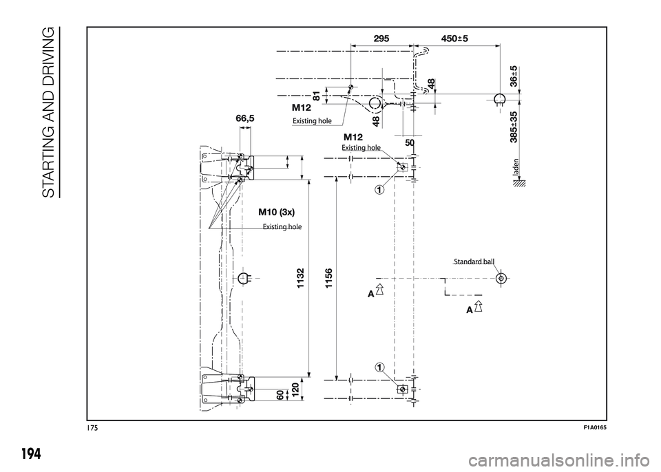
Installation diagram for
Truck and Chassis Cab
versions fig. 175
Another tow hook specific to Truck and
Chassis Cab versions in shown in fig.
175.
The structure Ø must be fixed in the
points indicated using a total of 6
M10x1.25 screws and 4 M12 screws.
MAX LOAD ON BALL: 100/120 kg
according to the payload (see
“Weights” table in the “Technical data”
section).
143)
WARNING
140) The ABS device with which the
vehicle may be equipped will not
control the braking system of
the trailer. Particular caution is
required on slippery roads.
141) Never modify the braking
system of the vehicle to control
the trailer brake. The trailer
braking system must be fully
independent from the hydraulic
system of the vehicle.142) After fitting, fixing screw holes
must be sealed to prevent an
exhaust gas inlet.
143) After fitting, fixing screw holes
must be sealed to prevent an
exhaust gas inlet.
192
STARTING AND DRIVING
Page 198 of 387
Existing hole
175F1A0165
194
STARTING AND DRIVING
Page 200 of 387
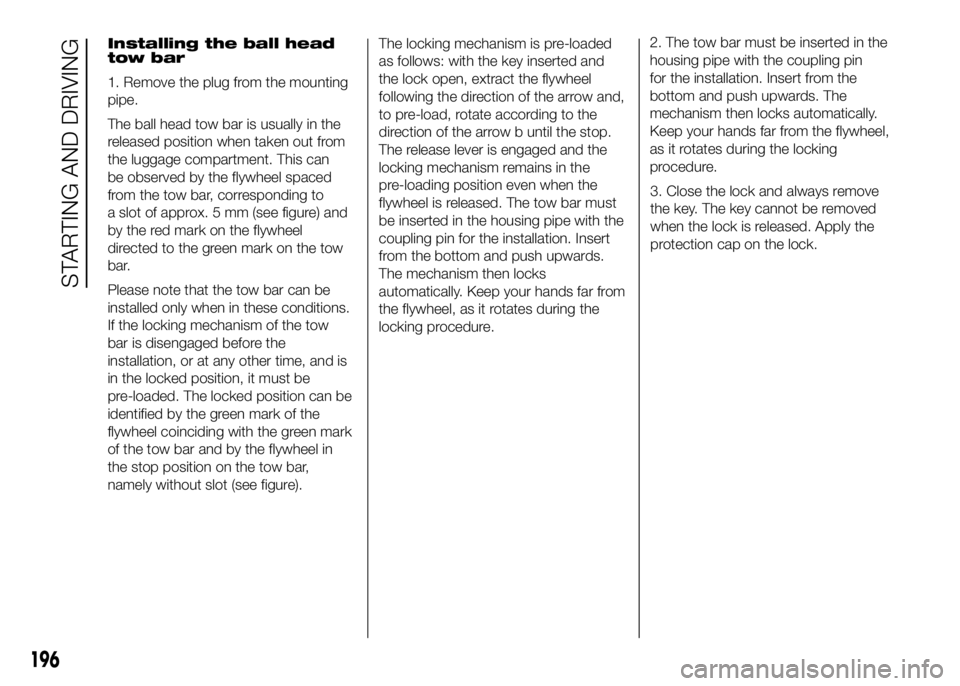
Installing the ball head
tow bar
1. Remove the plug from the mounting
pipe.
The ball head tow bar is usually in the
released position when taken out from
the luggage compartment. This can
be observed by the flywheel spaced
from the tow bar, corresponding to
a slot of approx. 5 mm (see figure) and
by the red mark on the flywheel
directed to the green mark on the tow
bar.
Please note that the tow bar can be
installed only when in these conditions.
If the locking mechanism of the tow
bar is disengaged before the
installation, or at any other time, and is
in the locked position, it must be
pre-loaded. The locked position can be
identified by the green mark of the
flywheel coinciding with the green mark
of the tow bar and by the flywheel in
the stop position on the tow bar,
namely without slot (see figure).The locking mechanism is pre-loaded
as follows: with the key inserted and
the lock open, extract the flywheel
following the direction of the arrow and,
to pre-load, rotate according to the
direction of the arrow b until the stop.
The release lever is engaged and the
locking mechanism remains in the
pre-loading position even when the
flywheel is released. The tow bar must
be inserted in the housing pipe with the
coupling pin for the installation. Insert
from the bottom and push upwards.
The mechanism then locks
automatically. Keep your hands far from
the flywheel, as it rotates during the
locking procedure.2. The tow bar must be inserted in the
housing pipe with the coupling pin
for the installation. Insert from the
bottom and push upwards. The
mechanism then locks automatically.
Keep your hands far from the flywheel,
as it rotates during the locking
procedure.
3. Close the lock and always remove
the key. The key cannot be removed
when the lock is released. Apply the
protection cap on the lock.
196
STARTING AND DRIVING
Page 202 of 387
SNOW TYRES
A Fiat Dealership will be happy to
provide advice concerning the most
suitable type of tyre for the customer's
requirements.
The performance of these tyres is
considerably reduced when the tread
depth is less than 4 mm. Replace them
in this case.
Due to the specific characteristics of
snow tyres, in normal weather
conditions or on long motorway
journeys, the performance of these
tyres is lower than that of standard
tyres. Their usage should therefore be
restricted in accordance with their
type approval.
IMPORTANT When using snow tyres
with a maximum speed index below the
one that can be reached by the vehicle
(increased by 5%), place a notice in
the passenger compartment, plainly in
view, which states the maximum speed
allowed by the snow tyres (as per EC
Directive).
All four tyres should be the same (brand
and track) to ensure greater safety
when driving and braking as well as a
good manoeuvrability.
Remember that you should not change
the rotation direction of the tyres.
144)
WARNING
144) The maximum speed for snow
tyres marked "Q" is 160 km/h,
while it is 190 km/h for "T" tyres
and 210 km/h for "H" tyres. You
should, however, always comply
with the speed limits of the
highway code.
SNOW CHAINS
The use of snow chains should be in
compliance with local regulations of
each country.
Snow chains can be fitted to the tyres
of the front wheels (drive wheels) only.
Use of Lineaccessori Fiat snow chains
is recommended. Check the tension
of the snow chains after the first few
metres have been driven.
43)
IMPORTANT With snow chains, use the
accelerator with extreme care to
prevent, or to limit as much as possible,
slipping of the drive wheels that could
cause chain breakage, resulting in
damage to the car body or mechanical
components.
IMPORTANT For versions fitted with
225/75 R16 tyre, use snow chains with
max. thickness 16 mm.
When travelling on snowy roads with
snow chains, it may be helpful to turn
the ASR off: in fact, in these conditions,
the driving wheels skidding when
moving off gives you better traction.
198
STARTING AND DRIVING
Page 205 of 387
IN AN EMERGENCY
A punctured tyre or a burnt-out bulb?
At times, a problem may interfere
with our journey.
The pages on emergencies can help
you to deal with critical situations
independently and with calm.
In an emergency we recommend that
you call the freephone number found in
the Warranty Booklet.
It is also possible to call the 00 800
3428 0000 freephone number to
search the nearest Fiat Dealership.STARTING THE ENGINE .................202
REPLACING A WHEEL ...................203
FIX & GO AUTOMATIC QUICK
TYRE REPAIR KIT ...........................208
CHANGING A BULB .......................212
REPLACING AN EXTERIOR BULB ..216
CHANGING AN INTERIOR BULB ....221
REPLACING FUSES........................222
BATTERY RECHARGING ................232
LIFTING THE VEHICLE....................233
TOWING THE VEHICLE ..................233
201
Page 206 of 387
STARTING THE
ENGINE
Go to a Fiat Dealership immediately if
warning light
stays on constantly on
the instrument panel.
JUMP STARTING
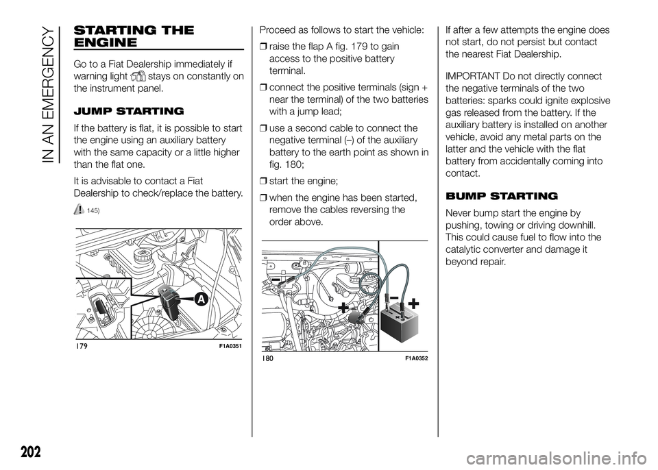
If the battery is flat, it is possible to start
the engine using an auxiliary battery
with the same capacity or a little higher
than the flat one.
It is advisable to contact a Fiat
Dealership to check/replace the battery.
145)
Proceed as follows to start the vehicle:
❒raise the flap A fig. 179 to gain
access to the positive battery
terminal.
❒connect the positive terminals (sign +
near the terminal) of the two batteries
with a jump lead;
❒use a second cable to connect the
negative terminal (–) of the auxiliary
battery to the earth point as shown in
fig. 180;
❒start the engine;
❒when the engine has been started,
remove the cables reversing the
order above.If after a few attempts the engine does
not start, do not persist but contact
the nearest Fiat Dealership.
IMPORTANT Do not directly connect
the negative terminals of the two
batteries: sparks could ignite explosive
gas released from the battery. If the
auxiliary battery is installed on another
vehicle, avoid any metal parts on the
latter and the vehicle with the flat
battery from accidentally coming into
contact.
BUMP STARTING
Never bump start the engine by
pushing, towing or driving downhill.
This could cause fuel to flow into the
catalytic converter and damage it
beyond repair.
179F1A0351
180F1A0352
202
IN AN EMERGENCY
Page 238 of 387
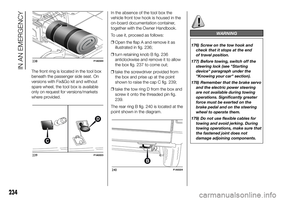
The front ring is located in the tool box
beneath the passenger side seat. On
versions with Fix&Go kit and without
spare wheel, the tool box is available
only on request for versions/markets
where provided.In the absence of the tool box the
vehicle front tow hook is housed in the
on-board documentation container,
together with the Owner Handbook.
To use it, proceed as follows:
❒Open the flap A and remove it as
illustrated in fig. 236;
❒turn retaining knob B fig. 236
anticlockwise and remove it to allow
the box fig. 237 to come out;
❒take the screwdriver provided from
the box and prise up at the point
shown to raise the cap C fig. 239;
❒take the tow ring D from the box and
screw it onto the threaded pin fig.
239.
The rear ring B fig. 240 is located at the
point shown in the diagram.
WARNING
176) Screw on the tow hook and
check that it stops at the end
of travel position.
177) Before towing, switch off the
steering lock (see "Starting
device" paragraph under the
"Knowing your car" section).
178) Remember that the brake servo
and the electric power steering
are not available during towing
operations. Significantly greater
force must be exerted on the
brake pedal and on the steering
wheel to operate them.
179) Do not use flexible cables for
towing and avoid jerking. During
towing operations, make sure that
the fastened joint does not
damage adjoining components.
238F1A0344
239F1A0223
240F1A0224
234
IN AN EMERGENCY