warning light FIAT DUCATO BASE CAMPER 2016 Owner handbook (in English)
[x] Cancel search | Manufacturer: FIAT, Model Year: 2016, Model line: DUCATO BASE CAMPER, Model: FIAT DUCATO BASE CAMPER 2016Pages: 387, PDF Size: 20.76 MB
Page 67 of 387
WARNING
29) If, after an impact, you smell fuel
or notice leaks from the fuel
system, do not reactivate the
switch to avoid the risk of fire.
30) Before reactivating the fuel
cut-off switch, carefully check for
fuel leaks or damage to the
vehicle's electrical devices (e.g.
headlights).
INTERIOR FITTINGS
UPPER STORAGE
COMPARTMENT -
REFRIGERATED
COMPARTMENT
(for versions/markets, where provided)
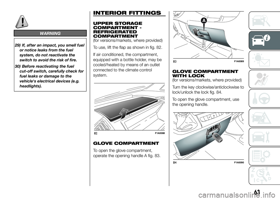
To use, lift the flap as shown in fig. 82.
If air conditioned, the compartment,
equipped with a bottle holder, may be
cooled/heated by means of an outlet
connected to the climate control
system.
GLOVE COMPARTMENT
To open the glove compartment,
operate the opening handle A fig. 83.GLOVE COMPARTMENT
WITH LOCK
(for versions/markets, where provided)
Turn the key clockwise/anticlockwise to
lock/unlock the lock fig. 84.
To open the glove compartment, use
the opening handle.
82F1A0088
83F1A0089
84F1A0090
63
Page 72 of 387
CAB GLOVE
COMPARTMENT
(CAPUCINE)
(for versions/markets, where provided)
The storage compartment is fitted
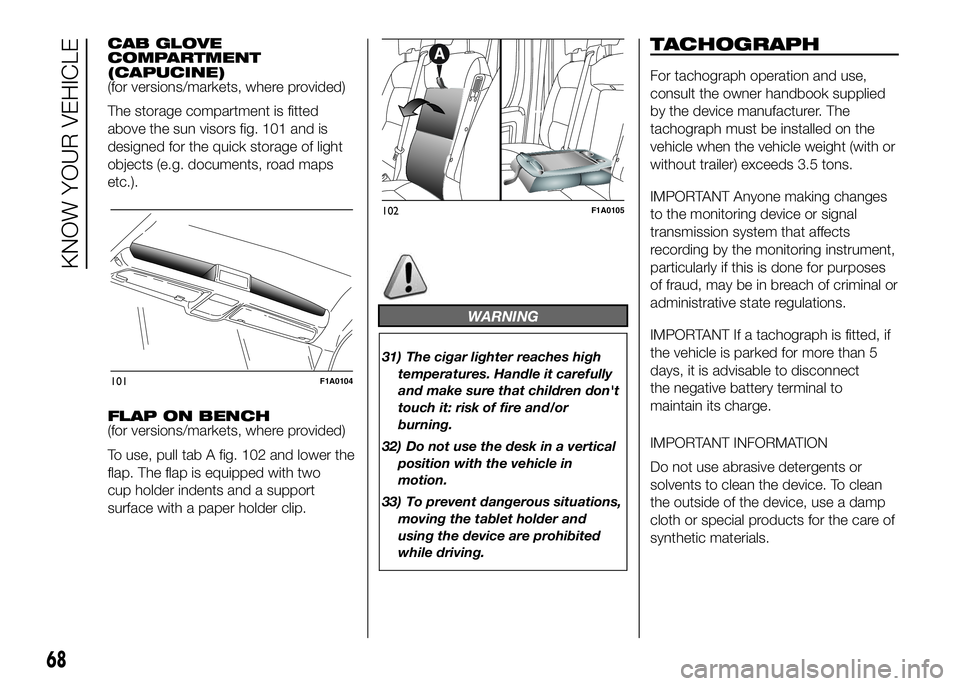
above the sun visors fig. 101 and is
designed for the quick storage of light
objects (e.g. documents, road maps
etc.).
FLAP ON BENCH
(for versions/markets, where provided)
To use, pull tab A fig. 102 and lower the
flap. The flap is equipped with two
cup holder indents and a support
surface with a paper holder clip.
WARNING
31) The cigar lighter reaches high
temperatures. Handle it carefully
and make sure that children don't
touch it: risk of fire and/or
burning.
32) Do not use the desk in a vertical
position with the vehicle in
motion.
33) To prevent dangerous situations,
moving the tablet holder and
using the device are prohibited
while driving.
TACHOGRAPH
For tachograph operation and use,
consult the owner handbook supplied
by the device manufacturer. The
tachograph must be installed on the
vehicle when the vehicle weight (with or
without trailer) exceeds 3.5 tons.
IMPORTANT Anyone making changes
to the monitoring device or signal
transmission system that affects
recording by the monitoring instrument,
particularly if this is done for purposes
of fraud, may be in breach of criminal or
administrative state regulations.
IMPORTANT If a tachograph is fitted, if
the vehicle is parked for more than 5
days, it is advisable to disconnect
the negative battery terminal to
maintain its charge.
IMPORTANT INFORMATION
Do not use abrasive detergents or
solvents to clean the device. To clean
the outside of the device, use a damp
cloth or special products for the care of
synthetic materials.
101F1A0104
102F1A0105
68
KNOW YOUR VEHICLE
Page 75 of 387
DOORS
DOOR CENTRAL
LOCKING/UNLOCKING
Locking doors from the
outside
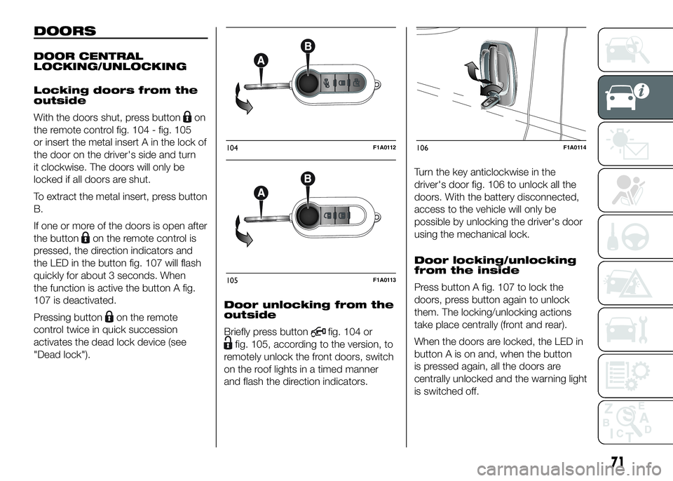
With the doors shut, press button
on
the remote control fig. 104 - fig. 105
or insert the metal insert A in the lock of
the door on the driver's side and turn
it clockwise. The doors will only be
locked if all doors are shut.
To extract the metal insert, press button
B.
If one or more of the doors is open after
the button
on the remote control is
pressed, the direction indicators and
the LED in the button fig. 107 will flash
quickly for about 3 seconds. When
the function is active the button A fig.
107 is deactivated.
Pressing button
on the remote
control twice in quick succession
activates the dead lock device (see
"Dead lock").Door unlocking from the
outside
Briefly press button
fig. 104 or
fig. 105, according to the version, to
remotely unlock the front doors, switch
on the roof lights in a timed manner
and flash the direction indicators.Turn the key anticlockwise in the
driver's door fig. 106 to unlock all the
doors. With the battery disconnected,
access to the vehicle will only be
possible by unlocking the driver's door
using the mechanical lock.
Door locking/unlocking
from the inside
Press button A fig. 107 to lock the
doors, press button again to unlock
them. The locking/unlocking actions
take place centrally (front and rear).
When the doors are locked, the LED in
button A is on and, when the button
is pressed again, all the doors are
centrally unlocked and the warning light
is switched off.
104F1A0112
105F1A0113
106F1A0114
71
Page 80 of 387
WARNING
34) Once the dead lock system is
engaged it is impossible to open
the doors from inside the vehicle.
Therefore, before engaging the
system check that there is no one
left inside. If the remote control
battery is flat, the system can be
disengaged only by inserting
the key metal insert in either of
the door locks as described
previously: in this case the device
remains active only for the rear
doors.
35) Before leaving the vehicle
parked with sliding doors open,
always check that the latch is
engaged.
36) Do not move the vehicle with
side doors open.37) Before setting off after parking
or before moving the vehicle in
any way, ensure that the
footboard is fully stowed away. As
the movement of the platform is
linked to that of the sliding side
door, thewarning light in the
instrument panel comes on if it is
not fully retracted in the same
way as when the rear doors are
not shut.
38) This spring loaded system has
activation forces that were
designed for optimum comfort.
Accidental knocks or a strong
gust of wind may release the
springs and close the doors
spontaneously.
39) With the doors opened to 180
degrees, no locking system is
effective. Do not use this opening
with the vehicle parked on a
gradient or when it is windy.
40) It is forbidden to drive the
vehicle with the footboard open.
41) Do not use the retracted
footboard for getting up or down
the load compartment.42) Make sure that the footboard is
suitably locked by the provided
retaining systems before, after
and during its use. An incomplete
opening or closing might cause
an improper movement of the
footboard with risks arising for the
operator and external users.
43) The footboard lightly projects
from the vehicle even if retracted;
therefore, when rear parking
sensors are provided, their
operating range is lightly reduced.
IMPORTANT
5) The footboard presence may
reduce the ramp approach angles;
it is therefore recommended, in
case of a very steep ramp, to
be very careful in order not to
damage the footboard.
76
KNOW YOUR VEHICLE
Page 85 of 387
ABS
This is an integral part of the braking
system, which prevents one or more
wheels from locking or slipping
regardless of the road surface
conditions and braking intensity,
ensuring control of the vehicle even
during emergency braking.
The system intervenes when braking
and the wheels are about to lock,
typically in emergency braking or
low-grip conditions, when locking may
be more frequent.
The ABS ensures the direction of the
vehicle while braking and optimises the
braking distances at the same time.
The system also improves control and
stability of the car when braking on a
surface where the grip of the left and
right wheels varies, or when braking on
corners.
The system is completed by EBD
(Electronic Braking Force Distribution),
which distributes the braking action
between the front and rear wheels.
IMPORTANT To obtain the maximum
efficiency of the braking system, a
bedding-in period of about 500 km is
needed: during this period it is better to
avoid sharp, repeated and prolonged
braking.
50)
SYSTEM INTERVENTION
The driver can feel that the ABS has
come into action because the brake
pedal pulsates slightly and the system
gets noisier: it means that the car
speed should be altered to suit the type
of road surface.
51) 52) 52) 53) 54) 55) 56) 57)
MSR SYSTEM
(Motor Schleppmoment Regelung)
This system is an integral part of the
ABS and intervenes, if there is sudden
downshifting, restoring torque to the
engine, thereby preventing excessive
drive at the drive wheels which,
especially in poor grip conditions, could
lead to a loss in stability of the vehicle.
WARNING
50) The ABS exploits the grip
available to the full, but it cannot
improve it. Therefore, you should
take great care when driving on
slippery surfaces, without taking
unnecessary risks.51) When the ABS intervenes and
you notice the brake pedal
pulsating, keep the pedal pushed
down and don’t be alarmed. This
will help you to stop in the
shortest distance possible,
depending on the road conditions.
52) If the ABS intervenes, it means
you have almost reached the grip
limit between the tyres and the
road surface: slow down to make
sure that you drive in accordance
with the available grip
53) The ABS can’t overrule the
natural laws of physics, and can’t
increase the grip available
according to the condition of the
road.
54) The ABS cannot prevent
accidents, including those due to
excessive speed on corners,
driving on low-grip surfaces or
aquaplaning.
55) The capability of the ABS must
never be tested irresponsibly and
dangerously, in such a way as
to compromise personal safety
and the safety of others.
56) For the correct operation of the
ABS, it is essential that the tyres
are of the same make and type on
all wheels, in perfect condition
and, above all, of the specified
type and dimensions.
81
Page 86 of 387
57) If the space-saver wheel (for
versions/markets, where
provided) is used, the ABS keeps
operating. Always remember
that the space-saver wheel, being
smaller than the original wheel,
provides less grip.ESC (Electronic
Stability Control)
SYSTEM
(for versions/markets, where provided)
The ESC system improves the
directional control and stability of the
vehicle in various driving conditions.
The ESC system corrects the vehicle’s
understeer and oversteer, distributing
the brake force on the appropriate
wheels. The torque supplied by the
engine can also be reduced in order to
maintain control of the vehicle.
The ESC system uses the sensors in
the vehicle to determine the trajectory
required by the driver through steering
and compares it with the real trajectory
of the vehicle. When the real trajectory
deviates from the desired trajectory, the
ESC system intervenes to counter the
car’s understeer or oversteer.
❒Oversteer: occurs when the vehicle is
turning more than it should according
to the angle of the steering wheel.
❒Understeer: occurs when the vehicle
is turning less than it should
according to the angle of the steering
wheelThe ESC system also includes the
following subsystems:
❒Hill Holder
❒ASR
❒HBA
❒ERM
❒HDC
58) 59) 60)
SYSTEM INTERVENTION
This is signalled by the flashing of
warning light
in the instrument panel,
to inform the driver that the vehicle is
in critical stability and grip conditions.
SYSTEM ACTIVATION
The ESC system switches on
automatically when the engine is
started and cannot be switched off.
82
KNOW YOUR VEHICLE
Page 89 of 387
After reaching the desired speed,
release the accelerator and brake
pedals completely (the LED on the
button flashes). If you want to
increase/decrease the speed, press the
accelerator/brake pedals again.
IMPORTANT Do not use the device
with the gearbox in neutral position.
IMPORTANT It is important to engage a
gear suitable for the set speed, to
prevent the engine from stalling.
When this function is active the brake
lights turn on automatically.
While the HDC system is operating it is
also possible to take control of the
vehicle again by pressing the brake and
accelerator pedals.
If the function is not made available
when the button is pressed, this could
be due to brake overheating. In this
case, wait a few minutes before using
the function again.
IMPORTANT The system is available for
speeds below 25 km/h.IMPORTANT Above 25 km/h the HDC
system deactivates but is still ready
to operate (the LED on the button
remains on) when the speed is again
below 25 km/h. If the speed exceeds
50 km/h, the HDC system deactivates
completely (the LED on the button
switches off) and the function does not
operate autonomously on the brakes
anymore. To reactivate it, press the
dedicated button again when the speed
is again below 25 km/h.
8)
WARNING
58) The ESC system can’t overrule
the natural laws of physics, and
can’t increase the grip available
according to the condition of
the road.
59) The ESC system cannot prevent
accidents, including those due to
excessive speed on corners,
driving on low-grip surfaces or
aquaplaning.60) The capability of the ESC system
must never be tested irresponsibly
and dangerously, in such a way
as to compromise personal safety
and the safety of others.
61) The performance of the ESC and
ASR systems must not encourage
the driver to take unnecessary
risks. Driving style must always be
adapted to road conditions,
visibility and traffic. The driver is,
in any case, responsible for safe
driving.
62) For the ESC and ASR systems to
function correctly, all four tyres
must be the same brand and type,
must be in excellent condition
and, above all, must be of the
prescribed type and size.
63) The HBA system cannot increase
tyre grip on the road over the
limits imposed by laws of physics:
always drive carefully according
to the conditions of the road
surface.
64) The HBA system cannot prevent
accidents, including those due to
excessive speed on bends,
travelling on low-grip surfaces or
aquaplaning.
85
Page 91 of 387
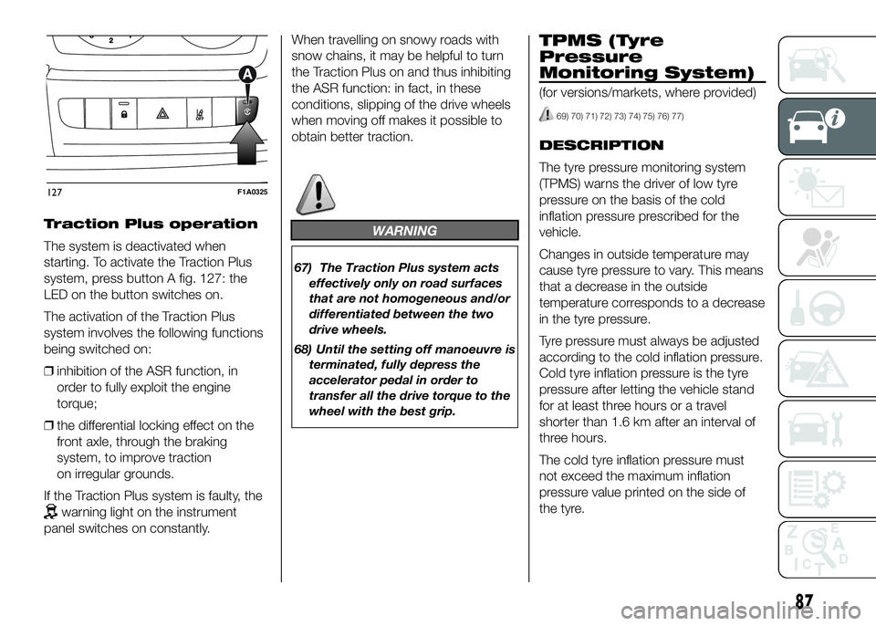
Traction Plus operation
The system is deactivated when
starting. To activate the Traction Plus
system, press button A fig. 127: the
LED on the button switches on.
The activation of the Traction Plus
system involves the following functions
being switched on:
❒inhibition of the ASR function, in
order to fully exploit the engine
torque;
❒the differential locking effect on the
front axle, through the braking
system, to improve traction
on irregular grounds.
If the Traction Plus system is faulty, the
warning light on the instrument
panel switches on constantly.When travelling on snowy roads with
snow chains, it may be helpful to turn
the Traction Plus on and thus inhibiting
the ASR function: in fact, in these
conditions, slipping of the drive wheels
when moving off makes it possible to
obtain better traction.
WARNING
67) The Traction Plus system acts
effectively only on road surfaces
that are not homogeneous and/or
differentiated between the two
drive wheels.
68) Until the setting off manoeuvre is
terminated, fully depress the
accelerator pedal in order to
transfer all the drive torque to the
wheel with the best grip.
TPMS (Tyre
Pressure
Monitoring System)
(for versions/markets, where provided)
69) 70) 71) 72) 73) 74) 75) 76) 77)
DESCRIPTION
The tyre pressure monitoring system
(TPMS) warns the driver of low tyre
pressure on the basis of the cold
inflation pressure prescribed for the
vehicle.
Changes in outside temperature may
cause tyre pressure to vary. This means
that a decrease in the outside
temperature corresponds to a decrease
in the tyre pressure.
Tyre pressure must always be adjusted
according to the cold inflation pressure.
Cold tyre inflation pressure is the tyre
pressure after letting the vehicle stand
for at least three hours or a travel
shorter than 1.6 km after an interval of
three hours.
The cold tyre inflation pressure must
not exceed the maximum inflation
pressure value printed on the side of
the tyre.
127F1A0325
87
Page 92 of 387
The tyre pressure also increases while
driving the vehicle: this is a normal
condition and does not require any
adjustment of the pressure.
The TPMS continues to advise the
driver of the low tyre pressure condition
until this is corrected; the warning
continues until the pressure
corresponds or exceeds the pressure
prescribed for the cold tyres. When the
tyre low pressure control warning
light
switches on constantly, the
inflation pressure must be adjusted until
it reaches the pressure prescribed for
cold tyres. After the automatic update
of the system, the tyre pressure control
warning light switches off. You may
need to drive the vehicle for about 20
minutes at a speed higher than 20
km/h to allow the TPMS to receive this
information.
NOTE
❒The TPMS does not replace the
normal tyre maintenance service and
does not indicate any fault in a tyre.
❒Therefore, the TPMS should not be
used as pressure switch while
adjusting the tyre inflation pressure.❒Driving with insufficient tyre pressure
causes their overheating and can
result in tyre failure. The low inflation
pressure reduces fuel efficiency
and tyre tread life and may also affect
handling and braking performance
of the vehicle.
❒The TPMS does not replace the
correct tyre maintenance. It is up to
the driver to maintain the correct tyre
pressure level measuring it with a
suitable pressure switch. This is
necessary even if the decrease in the
inflation pressure value does not
cause the tyre pressure control
warning light to switch on.
❒The TPMS warns the driver of any
condition of insufficient tyre pressure
If this drops below the insufficient
pressure limit for any reason including
low temperature and normal
pressure loss of the tyre.
❒The seasonal temperature changes
affect tyre pressure.
The TPMS uses wireless devices with
electronic sensors mounted on the
wheel rims to constantly monitor the
value of tyre pressure. The sensors
mounted on each wheel as part of the
valve stem transmit various information
of the tyres to the receiver module, in
order to calculate the pressure.WARNING Monitoring and maintaining
the correct pressure in all four tyres
are particularly important.
Tyre pressure
monitoring system low
pressure warnings
The system warns the driver if one or
more tyres are flat by switching on
the warning light
on the instrument
panel (together with a warning message
and an acoustic signal).
In this case, stop the vehicle as soon as
possible, check the inflation pressure
of each tyre and inflate to the cold tyre
pressure value prescribed for the
vehicle. The system will automatically
update and after receiving the tyre
pressure update the tyre pressure
control warning light switches off. You
may need to drive the vehicle for about
20 minutes at a speed higher than 20
km/h to allow the system to receive this
information.
88
KNOW YOUR VEHICLE
Page 93 of 387
TPMS operation faults
The system fault is indicated by
warning light
which first flashes for
75 seconds and then stays on steadily.
This can occur in any of the following
situations:
❒interference caused by electronic
devices or radio frequency emissions
similar to those of the TPM sensors.
❒Application of tinted films which
interfere with the signals of the radio
waves.
❒Presence of snow or ice on the
wheels or the wheel arches.
❒Use of snow chains.
❒Use of wheels/tyres not equipped
with TPM sensors.
❒The space-saver wheel is not
equipped with the tyre pressure
control sensor. Therefore, the tyre
pressure is not controlled by the
system.
❒If the space-saver wheel replaces a
tyre with a pressure lower than the
insufficient pressure limit, an acoustic
signal will be emitted and the warning
light
will switch on at the next
ignition cycle.❒When the original tyre is repaired or
replaced and it is mounted back on
the vehicle to replace the space-
saver wheel, the TPMS will update
automatically and the warning light
will switch off, provided that the
pressure of none of the four tyres is
below the insufficient pressure limit.
You may need to drive the vehicle for
about 20 minutes at a speed higher
than 20 km/h to allow the TPMS
to receive this information.IMPORTANT
INFORMATION
WARNING
69) The TPMS is optimised for the
original tyres and wheels
provided. TPMS pressures and
alerts have been defined
according to the size of the tyres
mounted on the vehicle. Using
equipment with different size,
type or kind may cause irregular
system operation or sensor
damage. Non-original spare
wheels can damage the sensor.
Do not use tyre sealant or
balancing weights if the vehicle is
equipped with TPMS as these
may damage the sensors.
70) If the system signals a pressure
decrease on a specific tyre, it is
recommended to check the
pressure on all four tyres.
71) TPMS does not relieve the driver
from the obligation to check the
tyre pressure every month; it is
not even to be considered a
replacing system for maintenance
or a safety system.
89