window FIAT DUCATO BASE CAMPER 2016 Owner handbook (in English)
[x] Cancel search | Manufacturer: FIAT, Model Year: 2016, Model line: DUCATO BASE CAMPER, Model: FIAT DUCATO BASE CAMPER 2016Pages: 387, PDF Size: 20.76 MB
Page 79 of 387
Manual opening of the
second swing door
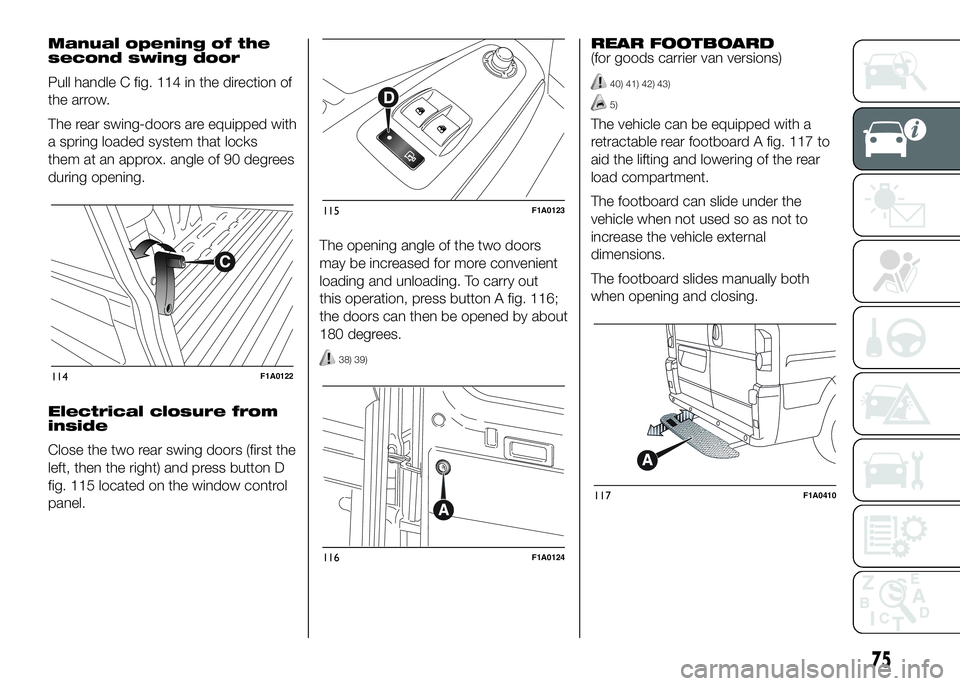
Pull handle C fig. 114 in the direction of
the arrow.
The rear swing-doors are equipped with
a spring loaded system that locks
them at an approx. angle of 90 degrees
during opening.
Electrical closure from
inside
Close the two rear swing doors (first the
left, then the right) and press button D
fig. 115 located on the window control
panel.The opening angle of the two doors
may be increased for more convenient
loading and unloading. To carry out
this operation, press button A fig. 116;
the doors can then be opened by about
180 degrees.
38) 39)
REAR FOOTBOARD
(for goods carrier van versions)
40) 41) 42) 43)
5)
The vehicle can be equipped with a
retractable rear footboard A fig. 117 to
aid the lifting and lowering of the rear
load compartment.
The footboard can slide under the
vehicle when not used so as not to
increase the vehicle external
dimensions.
The footboard slides manually both
when opening and closing.
114F1A0122
115F1A0123
116F1A0124
117F1A0410
75
Page 81 of 387
ELECTRIC WINDOWS
ELECTRIC
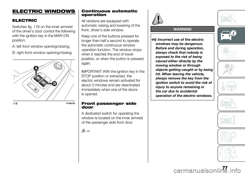
Switches fig. 118 on the inner armrest
of the driver's door control the following
with the ignition key in the MAR-ON
position:
A: left front window opening/closing;
B: right front window opening/closing.Continuous automatic
operation
All versions are equipped with
automatic raising and lowering of the
front, driver's side window.
Keep one of the buttons pressed for
longer than half a second to operate
the automatic continuous window
operation function. The window stops
when it reaches the end of travel
position, or when the button is pressed
again.
IMPORTANT With the ignition key in the
STOP position or extracted, the
electric windows remain activated for
about 3 minutes and are deactivated
immediately when one of the doors
is opened.
Front passenger side
door
A dedicated switch for operating the
window is located on the inner armrest
of the passenger side front door.
44)
WARNING
44) Incorrect use of the electric
windows may be dangerous.
Before and during operation,
always check that nobody is
exposed to the risk of being
injured either directly by the
moving window or through
objects getting caught or by being
hit. When leaving the vehicle,
always remove the key from the
ignition switch to avoid the risk of
injury to anyone remaining in
the car due to accidental
operation of the electric windows.
118F1A0125
77
Page 94 of 387
72) Tyre pressure must be checked
with tyres cold. Should it become
necessary for whatever reason
to check pressure with warm
tyres, do not reduce pressure
even if it is higher than the
prescribed value, but repeat the
check when tyres are cold.
73) The TPMS cannot indicate
sudden tyre pressure drops (for
example when a tyre bursts).
In this case, stop the car, braking
with caution and avoiding abrupt
steering.
74) The system only warns that the
tyre pressure is low: it is not able
to inflate them.
75) An insufficient tyre inflation
increases fuel consumption,
reduces the tread duration and
may affect the capacity of driving
safely.
76) Always refit the valve stem cap
after inspecting or adjusting tyre
pressure. This prevents dampness
or dirt from entering the valve
stem and thus the pressure
control sensor from being
damaged.77) The tyre repair kit (Fix&Go)
provided with the car (for
versions/markets, where
provided) is compatible with the
TPMS sensors; using sealants not
equivalent with that in the original
kit may adversely affect its
operation. If sealants not
equivalent with the original one
are used, it is recommended to
have the TPMS sensor operation
checked by a qualified repair
centre.DRIVING ADVISOR
(lane crossing warning)
(for versions/markets, where provided)
82) 79) 80)
The Driving Advisor is a warning system
that notifies the driver if he/she crosses
the lane because he/she has been
distracted.
A video sensor, fitted on the windscreen
near the interior rear view mirror,
detects the lane demarcation lines and
the position of the car in relation to
them.
IMPORTANT On cars with Driving
Advisor, it is advisable to contact a Fiat
Dealership should the windscreen
need to be replaced. If the repair is
carried out at a specialist window
replacement centre, it is still necessary
to go to a Fiat Dealership to have the
camera calibrated.
90
KNOW YOUR VEHICLE
Page 183 of 387
SIDE BAGS
121) 122) 123) 124) 125) 126) 127) 128) 129) 130)
131) 132) 133)
The vehicle is fitted with front side bags
for driver and passenger (for versions/
markets where provided) for protecting
the chest and window bags (for
versions/markets where provided) for
protecting front and rear passengers'
heads.
Side bags (for versions/markets where
provided) protect occupants from
side impacts of medium-high severity,
by placing the bag between the
occupant and the internal parts of the
side structure of the vehicle. Non-
activation of side bags in other types of
collisions (front collisions, rear shunts,
roll-overs, etc...) is not a system
malfunction.
An electronic control unit causes the
bags to inflate in the event of a side
impact. The bags inflate
instantaneously placing themselves
between the occupants' bodies and the
structures which could cause injury.
They deflate immediately afterwards.Side bags (for versions/markets where
provided) are not a replacement of
but complementary to the belts, which
you are recommended to always wear,
as specified by law in Europe and
most non-European countries.
FRONT SIDE BAGS FOR
CHEST PROTECTION
(for versions/markets, where provided)
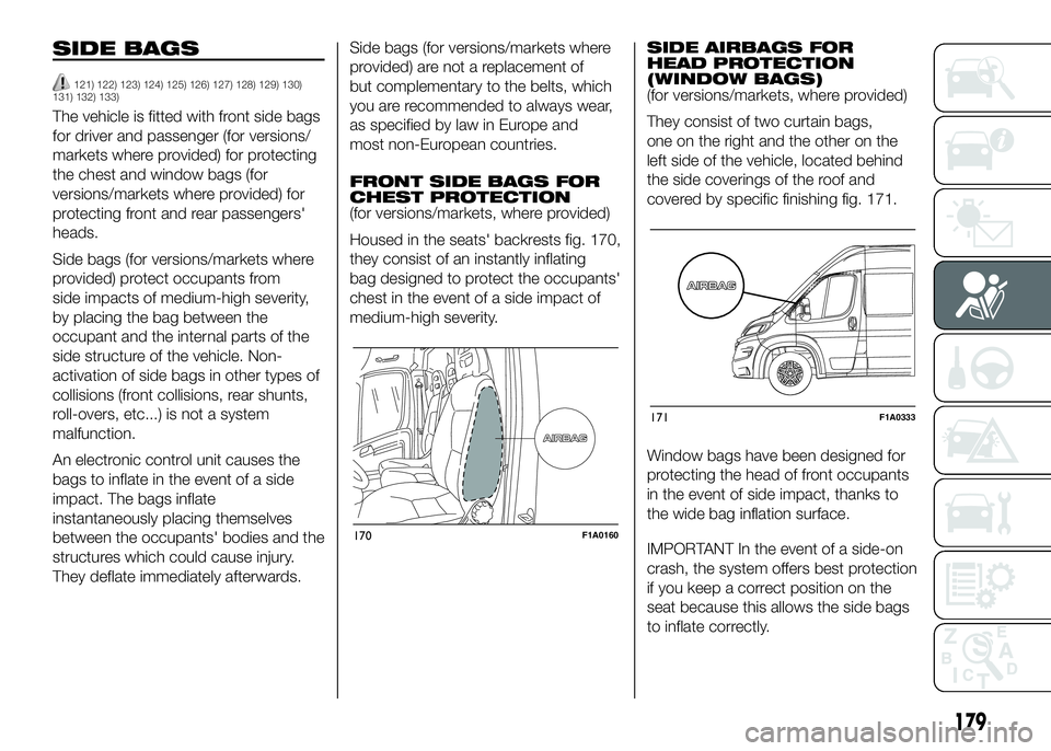
Housed in the seats' backrests fig. 170,
they consist of an instantly inflating
bag designed to protect the occupants'
chest in the event of a side impact of
medium-high severity.SIDE AIRBAGS FOR
HEAD PROTECTION
(WINDOW BAGS)
(for versions/markets, where provided)
They consist of two curtain bags,
one on the right and the other on the
left side of the vehicle, located behind
the side coverings of the roof and
covered by specific finishing fig. 171.
Window bags have been designed for
protecting the head of front occupants
in the event of side impact, thanks to
the wide bag inflation surface.
IMPORTANT In the event of a side-on
crash, the system offers best protection
if you keep a correct position on the
seat because this allows the side bags
to inflate correctly.
170F1A0160
171F1A0333
179
Page 184 of 387
IMPORTANT The front airbags and/or
side bags may be deployed if the
vehicle is subject to heavy knocks or
accidents involving the underbody area,
such as for example violent shocks,
against steps, kerbs or low obstacles,
vehicle falling into big potholes or
depressions in the road.
IMPORTANT A small amount of dust
will be released when the airbags
are deployed. The dust is not harmful
and does not indicate the beginning of
a fire. Furthermore, the surface of the
deployed bag and the interior of the
vehicle may be covered in a dusty
residue: this may irritate your skin and
eyes. Wash with mild soap and water in
the event of exposure.
IMPORTANT Should an accident occur
in which any of the safety devices are
activated, take the vehicle to a Fiat
Dealership to have the activated
devices replaced and to have the whole
system checked.
Every control, repair and replacement
operation concerning the airbags must
only be carried out at a Fiat Dealership.If you are having the vehicle scrapped,
have the system deactivated at a Fiat
Dealership first. If the vehicle changes
ownership, the new owner must be
informed of how to use the airbags and
the above warnings and also be given
this "Owner Handbook".
IMPORTANT Pretensioners, front
airbags and front side bags are
deployed differently according to the
type of collision. Failure to deploy
of one of the devices does not
necessarily indicate a system
malfunction.
WARNING
121) Never rest your head, arms or
elbows on the doors, on the
windows or in the window bag
area as this could cause injuries
during the inflation phase.
122) Never lean your head, arms and
elbows out of the window.123) If when turning the key to
MAR-ON the warning light
does not turn on or if it stays
on when travelling (together with
the message on the multifunction
display, for versions/markets
where provided), there could be a
fault in the safety systems; in
this event, airbags or
pretensioners may not trigger in
the case of impact or, in a lower
number of cases, they could be
triggered accidentally. Contact a
Fiat Dealership immediately to
have the system checked.
124) Do not cover the backrest of
the front or rear seats with covers
which are not suitable for use
with side bags.
125) Do not travel carrying objects in
your lap, in front of your chest or
between your lips (pipe, pencils,
etc.). They could cause severe
injury if the airbag is deployed.
126) Always drive keeping your
hands on the steering wheel rim
so that the airbag can inflate
freely if necessary. Do not drive
with your body bent forward.
Keep your back straight against
the backrest.
180
SAFETY
Page 193 of 387
Roof rack/ski rack
Remove the roof rack or the ski rack
from the roof after use. These
accessories decrease aerodynamic
penetration of the vehicle and have a
negative effect on fuel consumption.
When transporting particularly large
objects, use a trailer if possible.
Electric devices
Use electrical devices only for the
amount of time needed. The heated
rear window, additional headlights,
windscreen/rear window wipers and
heater fan need a considerable amount
of energy, therefore increasing fuel
consumption (by up to 25% in
the urban cycle).
Climate control system
Air conditioning leads to higher fuel
consumption (on average up to +20%).
If the temperature outside permits, try
and use the ventilation only.
Devices for
aerodynamic control
The use of non-certified spoilers may
adversely affect air drag and fuel
consumption.DRIVING STYLE
The main driving styles that affect fuel
consumption are listed below.
Cranking
Do not warm up the engine at low or
high revs when the vehicle is stationary;
this causes the engine to warm up
more slowly, thereby increasing fuel
consumption and emissions. It is
therefore advisable to move off
immediately, slowly, avoiding high
speeds: in this way the engine will
warm up more quickly.
Unnecessary actions
Avoid accelerating when stopped at
traffic lights or before switching off the
engine. This action and also double
declutching is absolutely pointless on
modern cars and also increases
consumption and pollution.
Gear selection
As soon as the conditions of the traffic
and road permit, use a higher gear.
Using a low gear for faster acceleration
will increase consumption.
In the same way improper use of a high
gear increases consumption, emissions
and engine wear.Max. speed
Fuel consumption increases
considerably with speed. Maintain a
constant speed, avoiding unnecessary
braking and acceleration, which cost
in terms of both fuel consumption and
emissions.
Acceleration
Accelerating violently will greatly affect
consumption and emissions:
acceleration should be gradual.
USAGE CONDITIONS
The main usage conditions that
negatively affect fuel consumption are
listed below.
Cold starting
Short journeys and frequent cold starts
do not allow the engine to reach
optimum operating temperature.
This results in a significant increase in
consumption levels (from +15 to +30%
on the urban cycle) and emissions.
189
Page 203 of 387
IMPORTANT
43) Keep your speed down when
snow chains are fitted; do not
exceed 50 km/h. Avoid potholes,
steps and pavements and avoid
driving for long distances on
roads not covered with snow to
prevent damaging the vehicle and
the roadbed.
PROLONGED
VEHICLE INACTIVITY
If the vehicle needs to be off the road
for longer than one month, the following
precautions must be taken:
❒park the vehicle indoors in a dry and,
if possible, well-ventilated place;
❒engage a gear;
❒check that the handbrake is not
engaged;
❒disconnect the negative battery
terminal; if the vehicle is equipped
with a battery disconnection function
(disconnector), see the description
of the procedure in the "Controls"
paragraph in the "Dashboard and
controls" section;
❒clean and protect the painted parts
using protective wax;
❒clean and protect the shiny metal
parts using special compounds
available commercially;
❒sprinkle talcum powder on the
windscreen and rear window wiper
rubber blades and lift them off the
glass;
❒slightly open the windows;❒cover the vehicle with a piece of
fabric or perforated plastic sheet. Do
not use compact plastic tarpaulins,
which prevent humidity from
evaporating from the surface of the
vehicle;
❒inflate tyres to +0.5 bar above the
standard specified pressure and
check it at intervals;
❒do not drain the engine cooling
system.
IMPORTANT If the vehicle is equipped
with an alarm system, switch off the
vehicle alarm with the remote control.
IMPORTANT After turning the ignition
key to STOP and having closed the
driver side door, wait at least one
minute before disconnecting the
electrical supply from the battery. When
reconnecting the electrical supply to
the battery, make sure that the ignition
key is in the STOP position and the
driver side door is closed.
199
Page 210 of 387
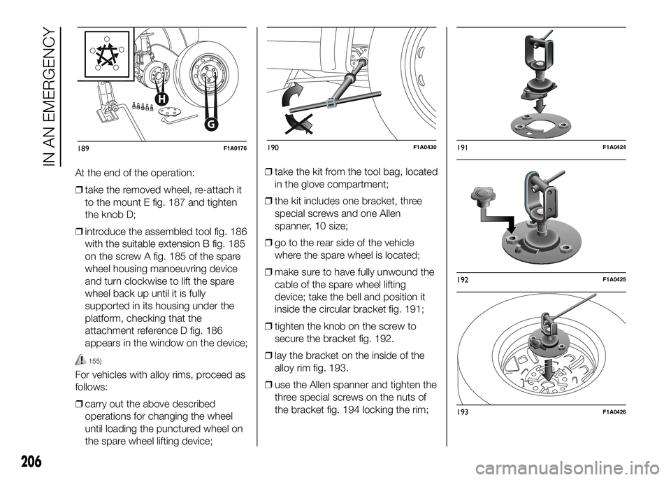
At the end of the operation:
❒take the removed wheel, re-attach it
to the mount E fig. 187 and tighten
the knob D;
❒introduce the assembled tool fig. 186
with the suitable extension B fig. 185
on the screw A fig. 185 of the spare
wheel housing manoeuvring device
and turn clockwise to lift the spare
wheel back up until it is fully
supported in its housing under the
platform, checking that the
attachment reference D fig. 186
appears in the window on the device;
155)
For vehicles with alloy rims, proceed as
follows:
❒carry out the above described
operations for changing the wheel
until loading the punctured wheel on
the spare wheel lifting device;❒take the kit from the tool bag, located
in the glove compartment;
❒the kit includes one bracket, three
special screws and one Allen
spanner, 10 size;
❒go to the rear side of the vehicle
where the spare wheel is located;
❒make sure to have fully unwound the
cable of the spare wheel lifting
device; take the bell and position it
inside the circular bracket fig. 191;
❒tighten the knob on the screw to
secure the bracket fig. 192.
❒lay the bracket on the inside of the
alloy rim fig. 193.
❒use the Allen spanner and tighten the
three special screws on the nuts of
the bracket fig. 194 locking the rim;
G
H
189F1A0176190F1A0430191F1A0424
192F1A0425
193F1A0426
206
IN AN EMERGENCY
Page 211 of 387
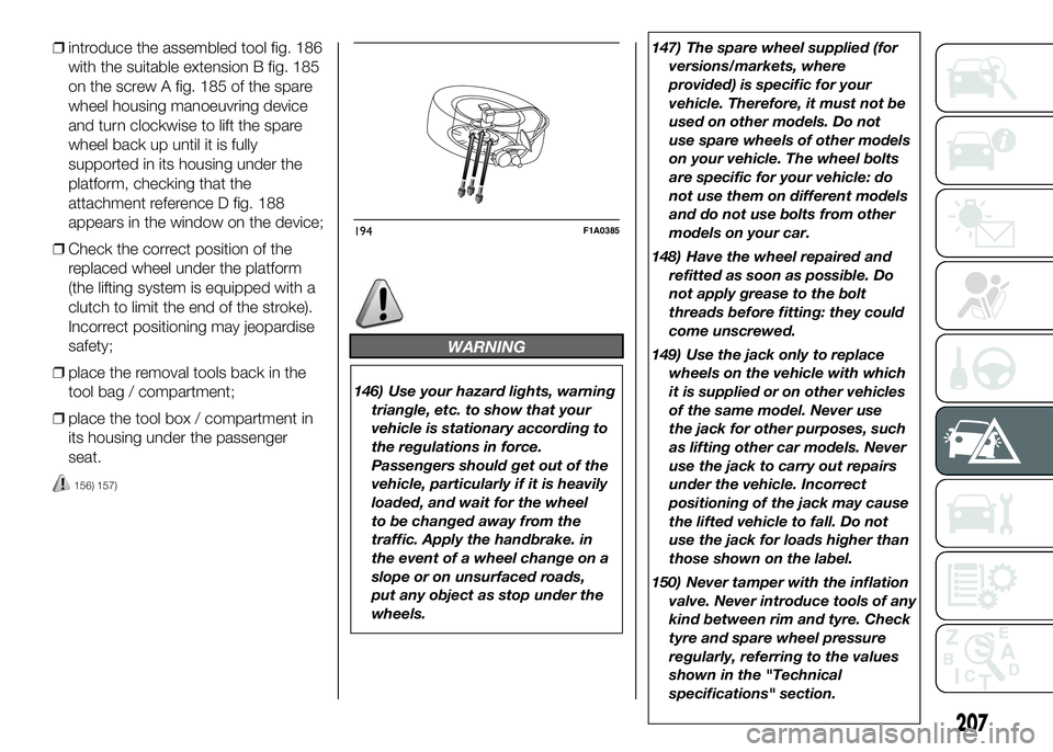
❒introduce the assembled tool fig. 186
with the suitable extension B fig. 185
on the screw A fig. 185 of the spare
wheel housing manoeuvring device
and turn clockwise to lift the spare
wheel back up until it is fully
supported in its housing under the
platform, checking that the
attachment reference D fig. 188
appears in the window on the device;
❒Check the correct position of the
replaced wheel under the platform
(the lifting system is equipped with a
clutch to limit the end of the stroke).
Incorrect positioning may jeopardise
safety;
❒place the removal tools back in the
tool bag / compartment;
❒place the tool box / compartment in
its housing under the passenger
seat.
156) 157)
WARNING
146) Use your hazard lights, warning
triangle, etc. to show that your
vehicle is stationary according to
the regulations in force.
Passengers should get out of the
vehicle, particularly if it is heavily
loaded, and wait for the wheel
to be changed away from the
traffic. Apply the handbrake. in
the event of a wheel change on a
slope or on unsurfaced roads,
put any object as stop under the
wheels.147) The spare wheel supplied (for
versions/markets, where
provided) is specific for your
vehicle. Therefore, it must not be
used on other models. Do not
use spare wheels of other models
on your vehicle. The wheel bolts
are specific for your vehicle: do
not use them on different models
and do not use bolts from other
models on your car.
148) Have the wheel repaired and
refitted as soon as possible. Do
not apply grease to the bolt
threads before fitting: they could
come unscrewed.
149) Use the jack only to replace
wheels on the vehicle with which
it is supplied or on other vehicles
of the same model. Never use
the jack for other purposes, such
as lifting other car models. Never
use the jack to carry out repairs
under the vehicle. Incorrect
positioning of the jack may cause
the lifted vehicle to fall. Do not
use the jack for loads higher than
those shown on the label.
150) Never tamper with the inflation
valve. Never introduce tools of any
kind between rim and tyre. Check
tyre and spare wheel pressure
regularly, referring to the values
shown in the "Technical
specifications" section.
194F1A0385
207
Page 212 of 387
151) No tools other than the crank
provided should be used with
the spare wheel lifting device; it
should be operated by hand only.
152) On versions equipped with
self-levelling air suspension, never
introduce the head or hands in
the wheel arch: the vehicle could
raise or lower automatically
depending on possible load or
temperature changes.
153) The device should only be
operated by hand, without using
any type of tool other than the
crank provided, like pneumatic or
electrical screwers.
154) The moving components of the
jack (screw and joints) can also
cause injuries: do not touch them.
If you come into contact with
lubricating grease, clean yourself
thoroughly.155) At the end of the operation of
raising/locking the spare wheel,
after having checked the correct
positioning of the wheel under the
platform (yellow notch inside the
window on the device), the
spanner must be extracted, taking
care not to turn it in the wrong
direction (as in fig. 190) to
facilitate the extraction of the
spanner itself, to prevent the
attachment device from being
released and the wheel assembly
not being securely retained.
156) Each time the spare wheel is
moved, check that it is correctly
positioned in its housing under
the platform. If it is not correctly
positioned, this could adversely
affect safety.
157) The spare wheel lifting device
is equipped with a clutch safety
system for its own protection; this
could activated if an excessive
load is applied on the
maneuvering screw.FIX&GO
AUTOMATIC QUICK
TYRE REPAIR KIT
(for versions/markets, where provided)
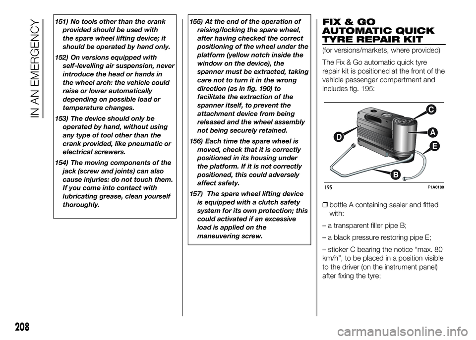
The Fix & Go automatic quick tyre
repair kit is positioned at the front of the
vehicle passenger compartment and
includes fig. 195:
❒bottle A containing sealer and fitted
with:
– a transparent filler pipe B;
– a black pressure restoring pipe E;
– sticker C bearing the notice “max. 80
km/h”, to be placed in a position visible
to the driver (on the instrument panel)
after fixing the tyre;
195F1A0180
208
IN AN EMERGENCY