ECO mode FIAT DUCATO BASE CAMPER 2016 Owner handbook (in English)
[x] Cancel search | Manufacturer: FIAT, Model Year: 2016, Model line: DUCATO BASE CAMPER, Model: FIAT DUCATO BASE CAMPER 2016Pages: 387, PDF Size: 20.76 MB
Page 50 of 387
❒To check the coolant level, follow the
instructions in the "Vehicle
maintenance" chapter, "Engine
coolant system fluid" paragraph. The
water in the heating circuit must
contain a minimum percentage of
10% antifreeze.
❒For maintenance and repairs, consult
only a Fiat Dealership and use only
original parts.
MAINTENANCE
Have the additional heater checked
regularly at a Fiat Dealership (and
always at the start of every winter). This
will guarantee safe and economic
operation of the heater as well as a long
duration.ADDITIONAL REAR
HEATING (Panorama and
Combi)
(for versions/markets, where provided)
The Panorama and Combi versions
are equipped with a main heating
system plus an additional system
(available on request) with controls in
the roof lining above the second row of
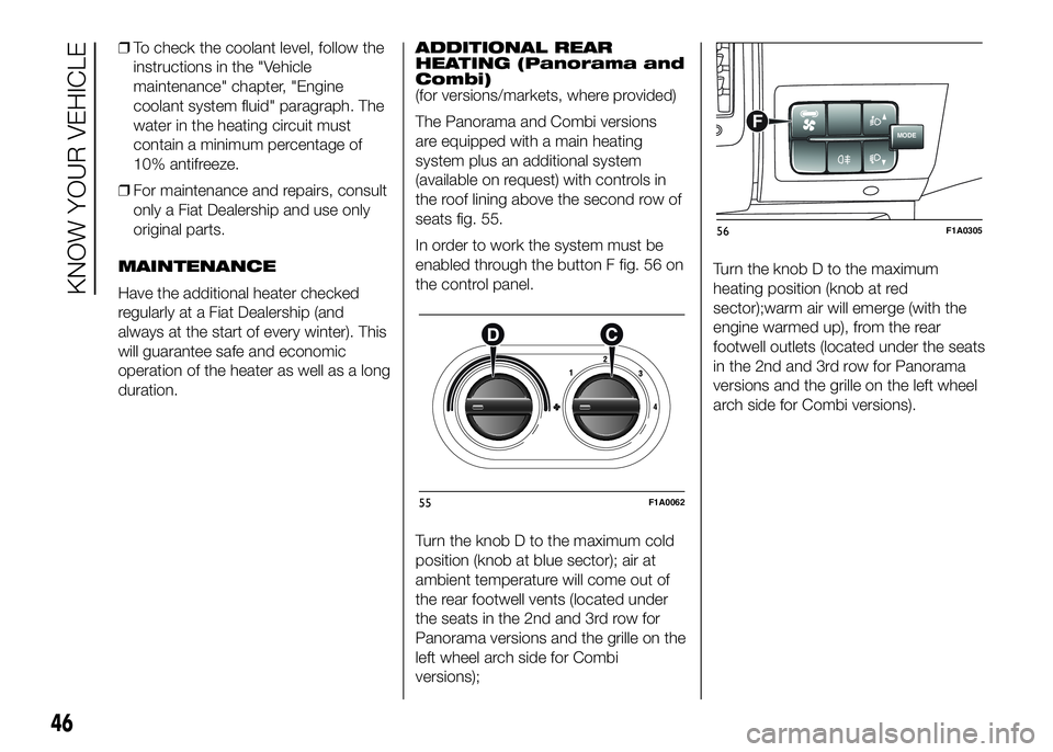
seats fig. 55.
In order to work the system must be
enabled through the button F fig. 56 on
the control panel.
Turn the knob D to the maximum cold
position (knob at blue sector); air at
ambient temperature will come out of
the rear footwell vents (located under
the seats in the 2nd and 3rd row for
Panorama versions and the grille on the
left wheel arch side for Combi
versions);Turn the knob D to the maximum
heating position (knob at red
sector);warm air will emerge (with the
engine warmed up), from the rear
footwell outlets (located under the seats
in the 2nd and 3rd row for Panorama
versions and the grille on the left wheel
arch side for Combi versions).
55F1A0062
MODEF
56F1A0305
46
KNOW YOUR VEHICLE
Page 56 of 387
WINDOW CLEANING
IN BRIEF
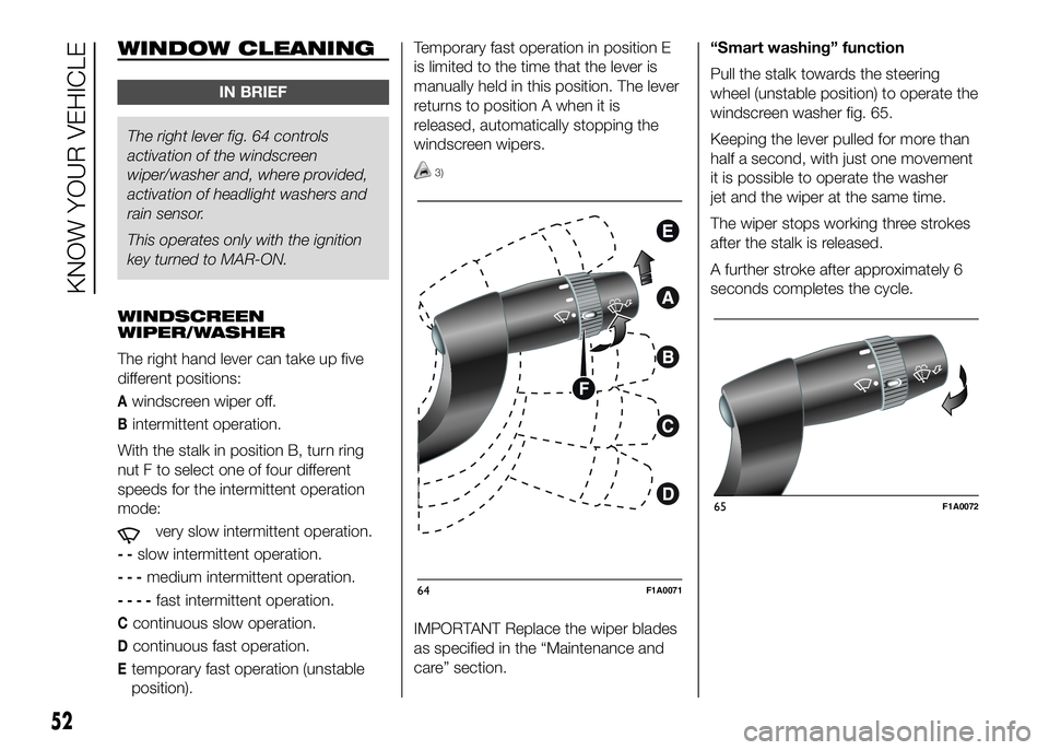
The right lever fig. 64 controls
activationof the windscreen
wiper/washer and, where provided,
activation of headlight washers and
rain sensor.
This operates only with the ignition
key turned to MAR-ON.
WINDSCREEN
WIPER/WASHER
The right hand lever can take up five
different positions:
Awindscreen wiper off.
Bintermittent operation.
With the stalk in position B, turn ring
nut F to select one of four different
speeds for the intermittent operation
mode:
very slow intermittent operation.
--slow intermittent operation.
---medium intermittent operation.
----fast intermittent operation.
Ccontinuous slow operation.
Dcontinuous fast operation.
Etemporary fast operation (unstable
position).Temporary fast operation in position E
is limited to the time that the lever is
manually held in this position. The lever
returns to position A when it is
released, automatically stopping the
windscreen wipers.
3)
IMPORTANT Replace the wiper blades
as specified in the “Maintenance and
care” section.“Smart washing” function
Pull the stalk towards the steering
wheel (unstable position) to operate the
windscreen washer fig. 65.
Keeping the lever pulled for more than
half a second, with just one movement
it is possible to operate the washer
jet and the wiper at the same time.
The wiper stops working three strokes
after the stalk is released.
A further stroke after approximately 6
seconds completes the cycle.
64F1A0071
65F1A0072
52
KNOW YOUR VEHICLE
Page 59 of 387
Storing vehicle speed
Proceed as follows:
❒turn ring nut A fig. 66 - fig. 67 to ON
or
(according to the version) and
press the accelerator pedal so that
the vehicle reaches the desired
speed;
❒move the stalk upwards (+) for at
least one second, then release it. The
vehicle speed is now stored and
you can therefore release the
accelerator pedal.
If necessary (e.g. when overtaking)
acceleration is possible by simply
pressing the accelerator pedal:
releasing the accelerator pedal the car
will return to the speed stored
previously.
Restoring the stored
speed
If the device has been deactivated, for
example by depressing the brake or
clutch pedal, the stored speed can be
restored as follows:
❒accelerate progressively until a speed
close to that stored is reached;
❒engage the gear selected at the time
that the speed was stored;
❒press button B fig. 66 - fig. 67.Increasing the stored
speed
This can be done in two ways:
❒by pressing the accelerator and
storing the new speed reached
or
❒by moving the stalk upwards (+).
Each activation of the lever
corresponds to an increase in speed of
about 1 km/h, whilst keeping the lever
upwards varies the speed continuously.
Reducing the stored
speed
This can be done in two ways:
❒by switching off the device and then
storing the new speed;
or
❒by moving the stalk downwards (-)
until the new speed, which will be
stored automatically, is reached.
Each movement of the lever will
correspond to a slight reduction in
speed of about 1 km/h, while keeping
the lever held downwards will decrease
the speed continuously.Deactivating the device
The device can be switched off by
the driver in the following ways:
❒turning ring nut A to OFF orO
(according to the version);
❒by stopping the engine;
Deactivating the
function
The device can be switched off by the
driver in the following ways:
❒turning ring nut A to OFF orO
(according to the version);
❒pressing the button B, both with
symbolIIand symbol CANC/RES,
the system pauses;
❒by stopping the engine;
❒by pressing the brake pedal or
operating the handbrake;
❒by pressing the clutch pedal;
❒requesting a gear shift with an
automatic transmission in sequential
mode;
❒with the vehicle speed below the set
limit
55
Page 62 of 387
ROOF LIGHTS
FRONT ROOF LIGHT WITH
SPOT LIGHTS
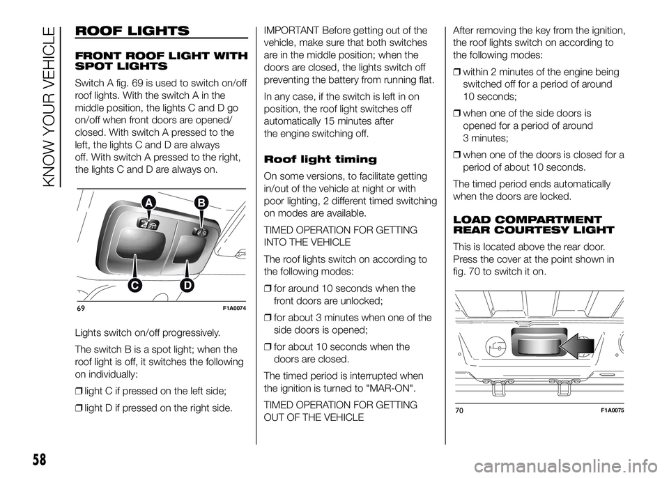
Switch A fig. 69 is used to switch on/off
roof lights. With the switch A in the
middle position, the lights C and D go
on/off when front doors are opened/
closed. With switch A pressed to the
left, the lights C and D are always
off. With switch A pressed to the right,
the lights C and D are always on.
Lights switch on/off progressively.
The switch B is a spot light; when the
roof light is off, it switches the following
on individually:
❒light C if pressed on the left side;
❒light D if pressed on the right side.IMPORTANT Before getting out of the
vehicle, make sure that both switches
are in the middle position; when the
doors are closed, the lights switch off
preventing the battery from running flat.
In any case, if the switch is left in on
position, the roof light switches off
automatically 15 minutes after
the engine switching off.
Roof light timing
On some versions, to facilitate getting
in/out of the vehicle at night or with
poor lighting, 2 different timed switching
on modes are available.
TIMED OPERATION FOR GETTING
INTO THE VEHICLE
The roof lights switch on according to
the following modes:
❒for around 10 seconds when the
front doors are unlocked;
❒for about 3 minutes when one of the
side doors is opened;
❒for about 10 seconds when the
doors are closed.
The timed period is interrupted when
the ignition is turned to "MAR-ON".
TIMED OPERATION FOR GETTING
OUT OF THE VEHICLEAfter removing the key from the ignition,
the roof lights switch on according to
the following modes:
❒within 2 minutes of the engine being
switched off for a period of around
10 seconds;
❒when one of the side doors is
opened for a period of around
3 minutes;
❒when one of the doors is closed for a
period of about 10 seconds.
The timed period ends automatically
when the doors are locked.
LOAD COMPARTMENT
REAR COURTESY LIGHT
This is located above the rear door.
Press the cover at the point shown in
fig. 70 to switch it on.
69F1A0074
70F1A0075
58
KNOW YOUR VEHICLE
Page 126 of 387
DISPLAY
(for versions/markets, where provided)
The vehicle may be equipped with a
multifunction display or with a
reconfigurable multifunction display,
able to display information that is useful
and necessary when driving.
MULTIFUNCTION
DISPLAY "STANDARD"
SCREEN
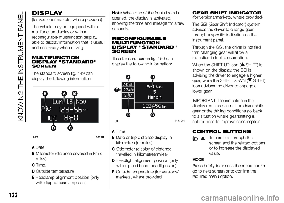
The standard screen fig. 149 can
display the following information:
ADate
BMilometer (distance covered in km or
miles).
CTime.
DOutside temperature
EHeadlamp alignment position (only
with dipped headlamps on).NoteWhen one of the front doors is
opened, the display is activated,
showing the time and mileage for a few
seconds.
RECONFIGURABLE
MULTIFUNCTION
DISPLAY "STANDARD"
SCREEN
The standard screen fig. 150 can
display the following information:
ATime
BDate or trip distance display in
kilometres (or miles)
COdometer (display of distance
travelled in kilometres/miles)
DHeadlight alignment position (only
with dipped beam headlights on)
EOutside temperature (for versions/
markets, where provided)GEAR SHIFT INDICATOR
(for versions/markets, where provided)
The GSI (Gear Shift Indicator) system
advises the driver to change gear
through a specific indication on the
instrument panel.
Through the GSI, the driver is notified
that changing gear will allow a
reduction in fuel consumption.
When the SHIFT UP icon (
SHIFT) is
shown on the display, the GSI is
advising the driver to engage a higher
gear, while the SHIFT DOWN (
SHIFT)
icon advises the driver to engage a
lower gear.
IMPORTANT The indication in the
display remains on until the driver shifts
gear or the driving conditions go back
to a situation where gearshifting is
not required to improve consumption.
CONTROL BUTTONS
To scroll up through the
screen and the related options
or to increase the displayed
value.
MODE
Press briefly to access the menu and/or
go to next screen or to confirm the
required menu option.
149F1A1040
150F1A1041
122
KNOWING THE INSTRUMENT PANEL
Page 129 of 387
NoteOn versions with reconfigurable
multifunction display adjustment can be
made both with lights off ("daytime"
mode brightness level) and with lights
on ("nighttime" mode brightness level).
Headlight alignment
(Headlight alignment
corrector position
adjustment)
(for versions/markets, where provided)
This function permits the adjustment (to
4 levels) of the headlight alignment
corrector position.
To carry out the adjustment, proceed as
follows:
❒briefly press the MODE button. The
level set previously flashes on the
display;
❒press button
orto adjust
the position;
❒briefly press the MODE button to
return to the menu screen or hold the
button down to return to the
standard screen without storing.Speed limit (Speed
Beep)
This function makes it possible to set
the vehicle speed limit (km/h or mph).
When this limit is exceeded the driver is
immediately alerted (see “Warning
lights and messages” section).
To set the desired speed limit, proceed
as follows:
- briefly press the MODE button: the
display will show the wording (Speed
Beep);
press button
orto select
speed limit activation (On) or
deactivation (Off);
- if the function has been activated (On),
press the
orbutton to
select the desired speed limit and then
press MODE to confirm.NoteSetting is possible between 30
and 200 km/h, or 20 and 125 mph,
according to the previously set unit.
See the "Setting the unit of
measurement (Measurement unit)"
paragraph described below. The setting
will increase/decrease by 5 units each
time button
/is pressed.
Hold down the
/button to
automatically increase/decrease the
setting rapidly. Complete the
adjustment with single presses of the
button when you approach the desired
value.
- press the MODE button briefly to
return to the menu screen or hold the
button down to return to the standard
screen without storing.
To cancel the setting, proceed as
follows:
- briefly press button MODE, (On) will
flash on the display;
- press button
, (Off) will flash on
the display;
- press the MODE button briefly to
return to the menu screen or hold the
button down to return to the standard
screen without storing.
125
Page 130 of 387
Headlight sensor
sensitivity adjustment
(for versions/markets, where provided)
With this function it is possible to adjust
the rain headlight sensitivity according
to 3 levels.
To set the required sensitivity level,
proceed as follows:
– briefly press the MODE button: the
previously set sensitivity “level” starts to
flash on the display;
– press the
orbutton to
make the adjustment;
– press the MODE button briefly to
return to the menu screen or hold the
button down to return to the standard
screen without storing.
Cornering lights
(Activation/deactivation of
“Cornering lights”)
(for versions/markets, where provided)
This function activates/deactivates
("On"/"Off") the cornering lights (see the
description in the “Exterior lights”
paragraph).
Proceed as follows to activate/
deactivate the lights:
❒briefly press the MODE button. "On"
or "Off" flash on the display,
according to what has been
previously set;❒press
orto make your
choice;
❒briefly press the MODE button to
return to the menu screen or hold the
button down to return to the
standard screen without storing.
Rain sensor
(Rain sensor setting adjustment)
(for versions/markets, where provided)
This function allows you to adjust the
rain sensor sensitivity to 4 levels.
To set the required sensitivity level,
proceed as follows:
❒briefly press the MODE button. The
sensitivity “level” set previously
flashes on the display;
❒press the
orbutton to
make the adjustment;
❒briefly press the MODE button to
return to the menu screen or hold the
button down to return to the
standard screen without storing.Trip B On/Off (Trip B
data)
This function can be used to activate
(On) or deactivate (Off) the Trip B
display (partial trip).
For more information see the "Trip
computer" paragraph.
For activation/deactivation, proceed as
follows:
- briefly press the MODE button: ON or
OFF flashes on the display (depending
the previous setting);
- press the
orbutton to
select;
- press the MODE button briefly to
return to the menu screen or hold the
button down to return to the standard
screen without storing.
Traffic sign
This function allows you to activate (On)
or deactivate (Off) the Traffic Sign
function to recognise the traffic signs
(no overtaking or speed limits).
For activation/deactivation, proceed as
follows:
- briefly press the MODE button: ON or
OFF flashes on the display (depending
the previous setting);
126
KNOWING THE INSTRUMENT PANEL
Page 137 of 387
IMPORTANT The reset operation when
“Trip B” details are being displayed
resets only the information associated
with this function.
Start of journey procedure
With the ignition key in the MAR-ON
position, reset by pressing the TRIP
button and keeping it pressed for more
than 2 seconds.
Trip Exit
You can automatically exit the TRIP
function once all the values have been
displayed or by holding the MODE
button down for more than 1 second.
IMPORTANT
21) The “Trip B” function may be
disabled (see paragraph
“Activating Trip B”). “Range” and
“Instant consumption"
parameters cannot be reset.
133
Page 190 of 387
34)
IMPORTANT Apply the handbrake only
when the vehicle is at a standstill or
with the vehicle in motion only in the
event of a failure in the hydraulic
system. If exceptional use is made of
the handbrake with the vehicle in
motion, moderate traction is advisable
in order not to cause locking of the
rear end with consequent swerving of
the vehicle.
WARNING
135) Never leave children
unattended in the vehicle. Always
remove the ignition key when
leaving the vehicle and take it out
with you.
IMPORTANT
34) If the vehicle is equipped with
self-levelling air suspension,
always check that there is
sufficient space above the roof
and around the vehicle when
parking. Indeed, the vehicle could
raise (or lower) automatically
depending on load or temperature
changes.
USING THE
GEARBOX
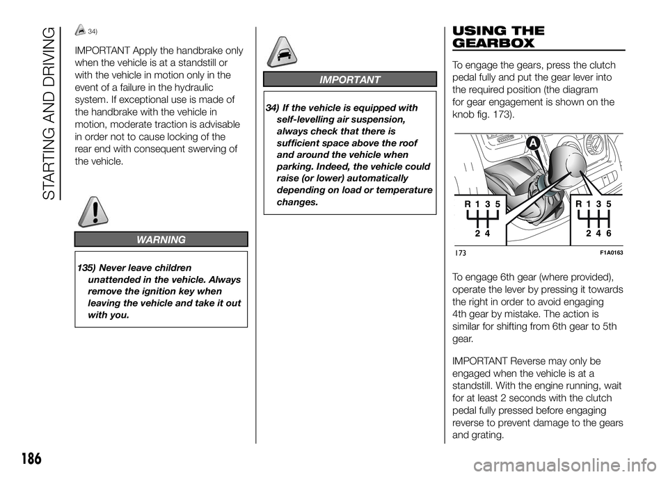
To engage the gears, press the clutch
pedal fully and put the gear lever into
the required position (the diagram
for gear engagement is shown on the
knob fig. 173).
To engage 6th gear (where provided),
operate the lever by pressing it towards
the right in order to avoid engaging
4th gear by mistake. The action is
similar for shifting from 6th gear to 5th
gear.
IMPORTANT Reverse may only be
engaged when the vehicle is at a
standstill. With the engine running, wait
for at least 2 seconds with the clutch
pedal fully pressed before engaging
reverse to prevent damage to the gears
and grating.
173F1A0163
186
STARTING AND DRIVING
Page 208 of 387
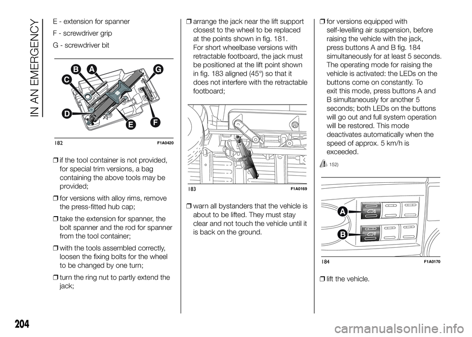
E - extension for spanner
F - screwdriver grip
G - screwdriver bit
❒if the tool container is not provided,
for special trim versions, a bag
containing the above tools may be
provided;
❒for versions with alloy rims, remove
the press-fitted hub cap;
❒take the extension for spanner, the
bolt spanner and the rod for spanner
from the tool container;
❒with the tools assembled correctly,
loosen the fixing bolts for the wheel
to be changed by one turn;
❒turn the ring nut to partly extend the
jack;❒arrange the jack near the lift support
closest to the wheel to be replaced
at the points shown in fig. 181.
For short wheelbase versions with
retractable footboard, the jack must
be positioned at the lift point shown
in fig. 183 aligned (45°) so that it
does not interfere with the retractable
footboard;
❒warn all bystanders that the vehicle is
about to be lifted. They must stay
clear and not touch the vehicle until it
is back on the ground.❒for versions equipped with
self-levelling air suspension, before
raising the vehicle with the jack,
press buttons A and B fig. 184
simultaneously for at least 5 seconds.
The operating mode for raising the
vehicle is activated: the LEDs on the
buttons come on constantly. To
exit this mode, press buttons A and
B simultaneously for another 5
seconds; both LEDs on the buttons
will go out and full system operation
will be restored. This mode
deactivates automatically when the
speed of approx. 5 km/h is
exceeded.
152)
❒lift the vehicle.
182F1A0420
183F1A0169
184F1A0170
204
IN AN EMERGENCY