brakes FIAT DUCATO BASE CAMPER 2016 Owner handbook (in English)
[x] Cancel search | Manufacturer: FIAT, Model Year: 2016, Model line: DUCATO BASE CAMPER, Model: FIAT DUCATO BASE CAMPER 2016Pages: 387, PDF Size: 20.76 MB
Page 88 of 387
When travelling on snowy roads with
snow chains, it may be helpful to turn
the ASR off: in fact, in these conditions,
the driving wheels slipping when
moving off gives you better traction.
HBA SYSTEM
(Hydraulic Brake Assist)
The HBA system is designed to
improve the vehicle’s braking capacity
during emergency braking. The system
detects emergency braking by
monitoring the speed and strength with
which the brake pedal is pressed,
thereby applying the optimal brake
pressure.
This can reduce the braking distance:
the HBA system therefore completes
the ABS.
Maximum assistance from the HBA
system is obtained by pressing the
brake pedal very quickly. In addition,
the brake pedal must be pressed
continuously during braking, avoiding
intermittent presses, to benefit from the
system.
Do not reduce pressure on the brake
pedal until braking is not necessary
anymore.
The HBA system is deactivated when
the brake pedal is released.
63) 64) 65)
ERM ELECTRONIC ROLLOVER
MITIGATION SYSTEM
(Electronic Rollover Mitigation)
The system monitors the tendency of
the wheels to rise from the ground if the
driver performs extreme manoeuvres
like quick steering to avoid an obstacle,
especially in poor road conditions.
If these conditions occur, the system
intervenes on the brakes and engine
power to reduce the possibility that the
wheels are raised from the ground.
It is not possible to avoid the tendency
to roll over if this is due to reasons
such as driving on high side gradients,
collision with objects or other vehicles.
66)
HILL DESCENT CONTROL
(HDC) SYSTEM
It is an integral part of the ESC and is
aimed at keeping the vehicle at a
constant speed during a descent,
operating autonomously on the brakes
in various ways at the same time. In this
way the vehicle stability and completely
safe driving are guaranteed, above all
in poor grip conditions and/or steep
descents.
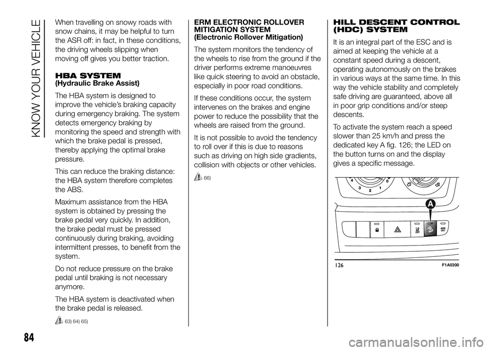
To activate the system reach a speed
slower than 25 km/h and press the
dedicated key A fig. 126; the LED on
the button turns on and the display
gives a specific message.
126F1A0300
84
KNOW YOUR VEHICLE
Page 89 of 387
After reaching the desired speed,
release the accelerator and brake
pedals completely (the LED on the
button flashes). If you want to
increase/decrease the speed, press the
accelerator/brake pedals again.
IMPORTANT Do not use the device
with the gearbox in neutral position.
IMPORTANT It is important to engage a
gear suitable for the set speed, to
prevent the engine from stalling.
When this function is active the brake
lights turn on automatically.
While the HDC system is operating it is
also possible to take control of the
vehicle again by pressing the brake and
accelerator pedals.
If the function is not made available
when the button is pressed, this could
be due to brake overheating. In this
case, wait a few minutes before using
the function again.
IMPORTANT The system is available for
speeds below 25 km/h.IMPORTANT Above 25 km/h the HDC
system deactivates but is still ready
to operate (the LED on the button
remains on) when the speed is again
below 25 km/h. If the speed exceeds
50 km/h, the HDC system deactivates
completely (the LED on the button
switches off) and the function does not
operate autonomously on the brakes
anymore. To reactivate it, press the
dedicated button again when the speed
is again below 25 km/h.
8)
WARNING
58) The ESC system can’t overrule
the natural laws of physics, and
can’t increase the grip available
according to the condition of
the road.
59) The ESC system cannot prevent
accidents, including those due to
excessive speed on corners,
driving on low-grip surfaces or
aquaplaning.60) The capability of the ESC system
must never be tested irresponsibly
and dangerously, in such a way
as to compromise personal safety
and the safety of others.
61) The performance of the ESC and
ASR systems must not encourage
the driver to take unnecessary
risks. Driving style must always be
adapted to road conditions,
visibility and traffic. The driver is,
in any case, responsible for safe
driving.
62) For the ESC and ASR systems to
function correctly, all four tyres
must be the same brand and type,
must be in excellent condition
and, above all, must be of the
prescribed type and size.
63) The HBA system cannot increase
tyre grip on the road over the
limits imposed by laws of physics:
always drive carefully according
to the conditions of the road
surface.
64) The HBA system cannot prevent
accidents, including those due to
excessive speed on bends,
travelling on low-grip surfaces or
aquaplaning.
85
Page 90 of 387
65) The HBA system is an aid for the
driver, who must always pay full
attention while driving. The
responsibility always rests with
the driver. The features of the
HBA system must never be tested
in imprudent or dangerous ways,
with the possibility of putting
the safety of the driver, occupants
or other road users at risk.
66) The performance of a vehicle
with ERM must never be tested
in imprudent or dangerous ways,
with the possibility of putting
the safety of the driver or other
people at risk.
IMPORTANT
8) Prolonged use of the system may
overheat the braking system. If
the brakes overheat, the HDC
system, when active, will be
gradually deactivated after
suitably informing the driver (the
LED on the button turns off): it
can be reactivated only when the
brakes have cooled sufficiently.
The distance that can be covered
depends on the temperature of
the brakes and therefore on the
gradient, load and speed of the
vehicle.
TRACTION PLUS
SYSTEM
(for versions/markets, where provided)
Traction Plus is a driving aid, useful
for setting off in poor grip conditions on
non-homogeneous road surfaces
(snow/asphalt, ice/asphalt, mud/
asphalt, etc.), which allows the drive
force to be distributed adequately
on the engine axle when one of the two
drive wheels slips.
Traction Plus acts by braking the wheel
with poor grip (or slipping more than
the others), thereby transferring the
drive force to that which has greater
grip on the ground.
This function can be activated manually
by pressing button A on the dashboard
fig. 127 and operates under 50 km/h.
When this speed is exceeded, it is
automatically deactivated (the LED on
the button is still on) and it is
reactivated again when the speed falls
below 30 km/h.
67) 68)
86
KNOW YOUR VEHICLE
Page 112 of 387
Fiat Auto S.p.A. shall not be liable for
damage caused by the installation
of accessories either not supplied or
recommended by Fiat Auto S.p.A.
and/or not installed in compliance with
the instructions provided.
RADIO TRANSMITTERS
AND MOBILE PHONES
Radio transmitter equipment (vehicle
mobile phones, CB radios, amateur
radio etc.) cannot be used inside the
car unless a separate aerial is mounted
externally.
IMPORTANT The use of these devices
inside the passenger compartment
(without an external aerial) may cause
the electrical systems to malfunction.
This could compromise the safety
of the car in addition to constituting a
potential hazard for passengers' health.
In addition, transmission and reception
of these devices may be affected by the
shielding effect of the car body.
As far as the use of EC-approved
mobile phones is concerned (GSM,
GPRS, UMTS), follow the usage
instructions provided by the mobile
phone manufacturer.PROVISION FOR FITTING
TELEPASS ON
REFLECTIVE
WINDSCREEN
(for versions/markets, where provided)
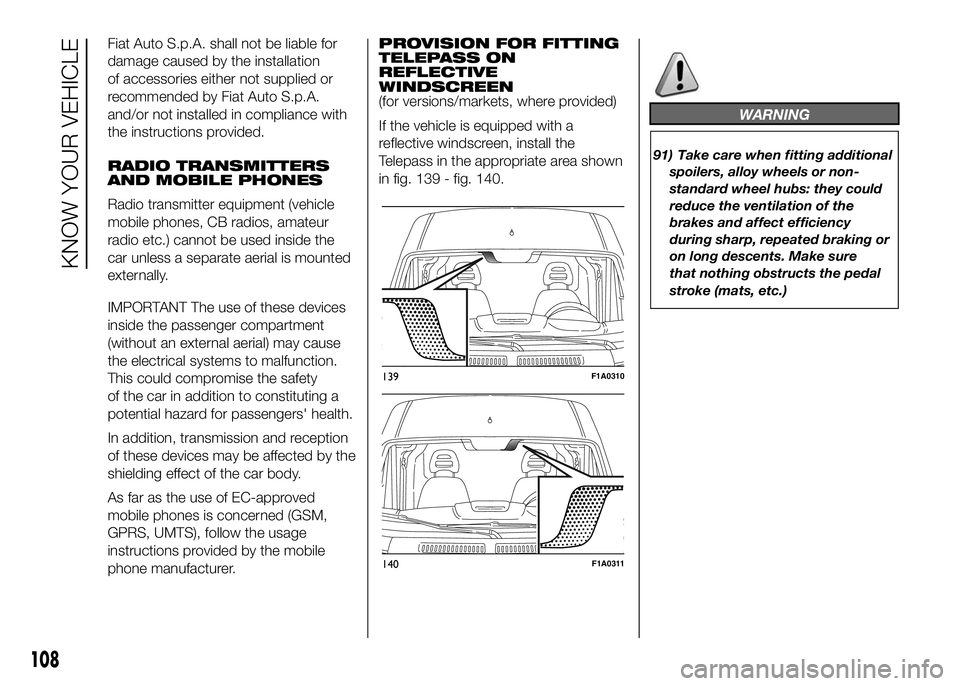
If the vehicle is equipped with a
reflective windscreen, install the
Telepass in the appropriate area shown
in fig. 139 - fig. 140.
WARNING
91) Take care when fitting additional
spoilers, alloy wheels or non-
standard wheel hubs: they could
reduce the ventilation of the
brakes and affect efficiency
during sharp, repeated braking or
on long descents. Make sure
that nothing obstructs the pedal
stroke (mats, etc.)
139F1A0310
140F1A0311
108
KNOW YOUR VEHICLE
Page 195 of 387
For the electric connection a standard
connector should be used which is
generally placed on a special bracket
normally fastened to the towing device,
and a special ECU for external trailer
light control must be installed on the
vehicle. For the electrical connection, 7
or 13 pin 12 V DC connections are to
be used (CUNA/UNI and ISO/DIN
Standards). Follow the instructions
provided by the vehicle manufacturer
and/or the tow hitch manufacturer.
An electric brake (or electric winch)
should be supplied directly by the
battery through a cable with a cross
section of no less than 2.5 mm
2.
IMPORTANT Electric brakes or other
devices must be used with engine
running.
In addition to the electrical branches,
the vehicle's electric system can only
be connected to the supply cable for an
electric brake and to the cable for an
internal light, though not above 15
W. For connections use the preset
control unit with battery cable no less
than 2.5 mm
2.IMPORTANT The trailer tow hook
contributes to the length of the vehicle.
When installing on long wheelbase
versions, it is only possible to install
removable tow hooks because the total
vehicle length limit of 6 metres is
exceeded.
If no trailer is fitted, the hook must be
removed from the attachment base and
it must not exceed the vehicle's
original length.
IMPORTANT If you wish to leave the
tow hook fitted without towing a trailer,
it is advisable to contact a Fiat
Dealership for the relevant system
update operations because the tow
hook could be detected as an obstacle
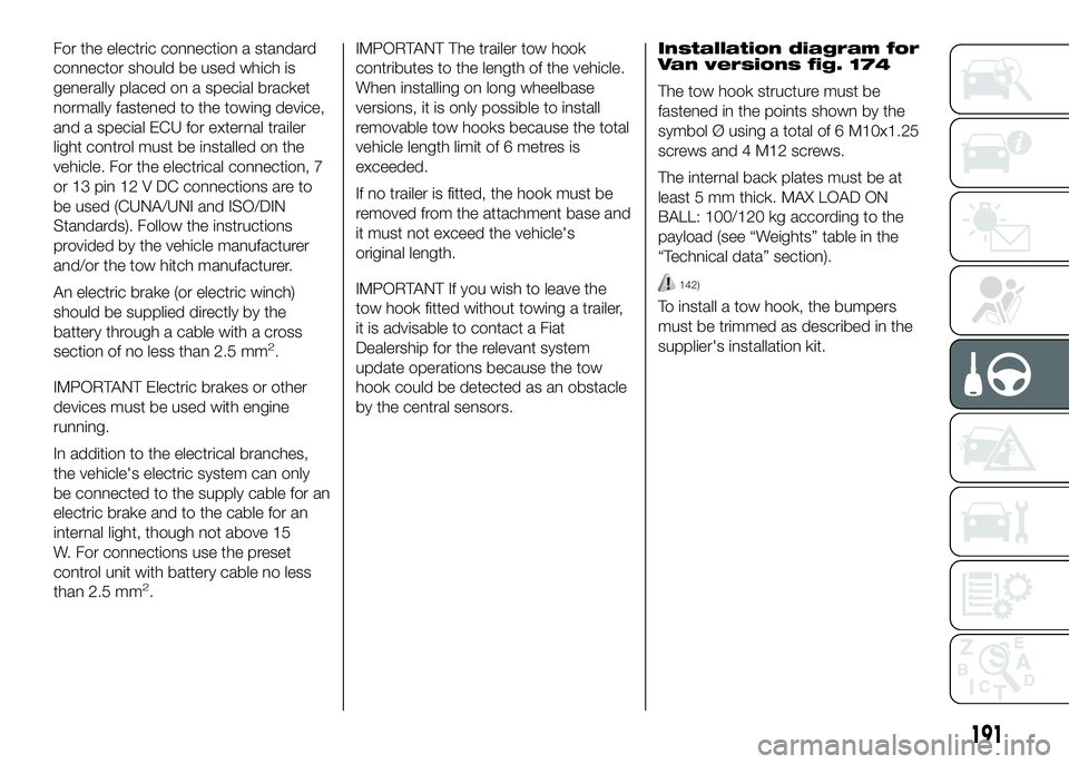
by the central sensors.Installation diagram for
Van versions fig. 174
The tow hook structure must be
fastened in the points shown by the
symbol Ø using a total of 6 M10x1.25
screws and 4 M12 screws.
The internal back plates must be at
least 5 mm thick. MAX LOAD ON
BALL: 100/120 kg according to the
payload (see “Weights” table in the
“Technical data” section).
142)
To install a tow hook, the bumpers
must be trimmed as described in the
supplier's installation kit.
191
Page 243 of 387

SCHEDULED SERVICING PLAN
Thousands of miles 30 60 90 120 150
Thousands of kilometres 48 96 144 192 240
Years246810
Check battery charge status and recharge if necessary●●●●●
Checktyre conditions/wear and adjust pressure, if required●●●●●
Check operation of lighting system (headlights, direction indicators, hazard
warning lights, luggage compartment, passenger compartment, glove
compartment, instrument panel warning lights, etc.)●●●●●
Check operation of windscreen wiper/washer system and adjust jets, if
necessary●●●●●
Check the position/wear of the windscreen/rear window wiper blades●●●●●
Check cleanliness of bonnet and luggage compartment locks, as well as
cleanliness and lubrication of linkages●●●●●
Visually inspect condition of: exterior bodywork, underbody protection,
pipes and hoses (exhaust, fuel system, brakes), rubber elements (boots,
sleeves, bushes, etc.)●●●●●
Check condition and wear of front disc brake pads and operation of pad
wear indicator●●●●●
Check condition and wear of rear disc brake pads and operation of pad
wear indicator (for versions/markets where provided)●●●●●
239
Page 246 of 387
PERIODIC CHECKS
Before long journeys, check and, if
necessary, restore:
❒engine coolant level;
❒brake fluid level;
❒control and recovery of additive level
for AdBlue Diesel emissions (UREA)
(for versions/markets, where
provided);
❒windscreen washer fluid level;
❒tyre inflation pressure and condition;
❒operation of lighting system
(headlamps, direction indicators,
hazard warning lights, etc.);
❒operation of screen washer/wiper
system and positioning/wear of
windscreen/rear window wiper
blades.
To ensure that the vehicle is always
efficient and well maintained, it is
advisable to make sure that you carry
out the above operations regularly
(approximately every 1000 km and
every 3000 km for checking and
topping up engine oil is advisable).
DEMANDING
VEHICLE USE
If the vehicle is mostly used in one of
the following conditions:
❒towing a trailer or caravan;
❒dusty roads;
❒short, repeated journeys (less than
7-8 km) at sub-zero outside
temperatures;
❒engine often idling or driving long
distances at low speeds or long
periods of inactivity;
the following checks must be carried
out more often than indicated in the
Scheduled Servicing Plan:
❒check front disc brake pad
conditions and wear;
❒check cleanliness of bonnet and boot
locks, cleanliness and lubrication of
linkage;
❒visually inspect conditions of: engine,
gearbox, transmission, pipes and
hoses (exhaust - fuel system -
brakes) and rubber elements (boots -
sleeves - bushes - etc.);
❒check battery charge and battery
fluid level (electrolyte);
❒visually inspect condition of the
accessory drive belts;❒check and, if necessary, change
engine oil and replace oil filter;
❒Restore additive level for AdBlue
Diesel emissions (UREA) (for versions
/ markets where applicable), at the
ignition of the lamp or the message
on the instrument panel;
❒check and, if necessary, replace
pollen filter.
242
SERVICING AND MAINTENANCE
Page 265 of 387
TECHNICAL SPECIFICATIONS
Everything you may find useful for
understanding how your vehicle
is made and works is contained in this
chapter and illustrated with data, tables
and graphics. For the enthusiasts and
the technician, but also just for those
who want to know every detail of their
vehicle.IDENTIFICATION DATA....................262
ENGINE CODES - BODYWORK
VERSION ........................................264
ENGINE ..........................................266
POWER SUPPLY ............................267
TRANSMISSION .............................268
SUSPENSION .................................268
BRAKES .........................................269
STEERING ......................................269
WHEELS .........................................270
DIMENSIONS ..................................274
PERFORMANCE .............................284
WEIGHTS........................................286
SUPPLIES .......................................327
FLUIDS AND LUBRICANTS ............329
FUEL CONSUMPTION ....................333
CO2 EMISSIONS ............................345
OFFICIAL TYPE APPROVALS .........356
PRESCRIPTIONS FOR HANDLING
THE VEHICLE AT THE END OF ITS
LIFE ................................................360
261
Page 273 of 387
IMPORTANT
56) Make sure that the leaf springs in composite material do not come into contact with any kind of acid
BRAKES
Front service brakes Rear service brakes Parking brake
self-ventilated discs discscontrolled by hand lever, working on rear
brakes
IMPORTANT Water, ice and salt spread on the roads may deposit on the brake discs reducing braking efficiency the first time
the brakes are applied.
STEERING
Versions Turning circle kerb to kerb (m) Type
Short wheelbase11,06
rackand pinion with hydraulic power
steering Medium wheelbase12,46
Medium-long wheelbase13,54
Long wheelbase14,28
Extra-long wheelbase15,3
269
Page 335 of 387
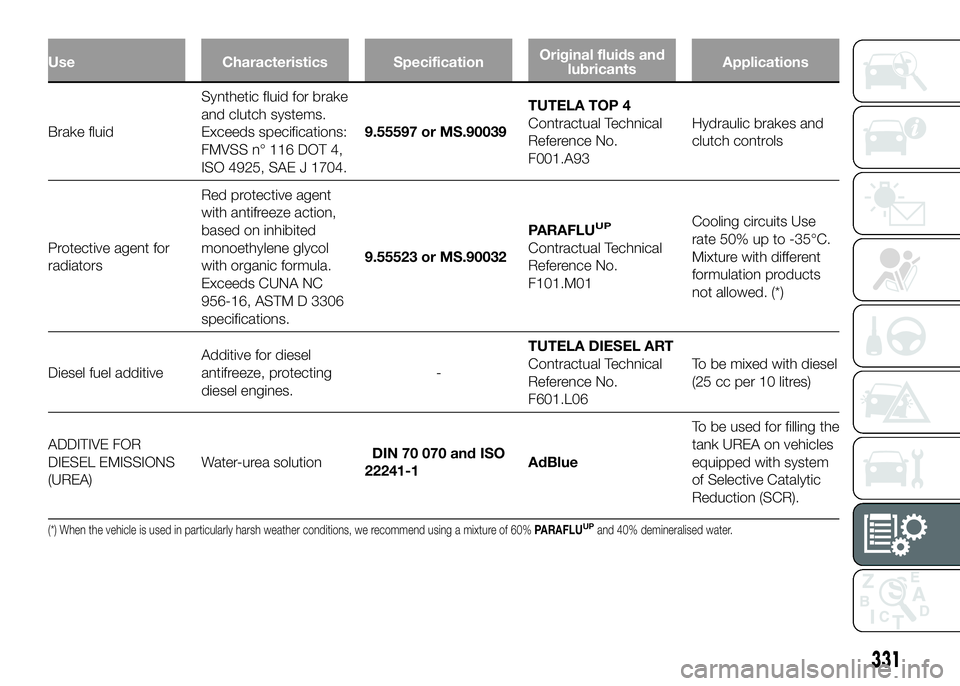
Use Characteristics SpecificationOriginal fluids and
lubricantsApplications
Brake fluidSynthetic
fluid for brake
and clutch systems.
Exceeds specifications:
FMVSS n° 116 DOT 4,
ISO 4925, SAE J 1704.9.55597 or MS.90039TUTELA TOP 4
Contractual Technical
Reference No.
F001.A93Hydraulic brakes and
clutch controls
Protective agent for
radiatorsRed protective agent
with antifreeze action,
based on inhibited
monoethylene glycol
with organic formula.
Exceeds CUNA NC
956-16, ASTM D 3306
specifications.9.55523 or MS.90032PARAFLU
UP
Contractual Technical
Reference No.
F101.M01Cooling circuits Use
rate 50% up to -35°C.
Mixture with different
formulation products
not allowed. (*)
Diesel fuel additiveAdditive for diesel
antifreeze, protecting
diesel engines.-TUTELA DIESEL ART
Contractual Technical
Reference No.
F601.L06To be mixed with diesel
(25 cc per 10 litres)
ADDITIVE FOR
DIESEL EMISSIONS
(UREA)Water-urea solutionDIN 70 070 and ISO
22241-1AdBlueTo be used for filling the
tank UREA on vehicles
equipped with system
of Selective Catalytic
Reduction (SCR).
(*) When the vehicle is used in particularly harsh weather conditions, we recommend using a mixture of 60%PARAFLUUPand 40% demineralised water.
331