radio FIAT DUCATO BASE CAMPER 2016 Owner handbook (in English)
[x] Cancel search | Manufacturer: FIAT, Model Year: 2016, Model line: DUCATO BASE CAMPER, Model: FIAT DUCATO BASE CAMPER 2016Pages: 387, PDF Size: 20.76 MB
Page 11 of 387
.
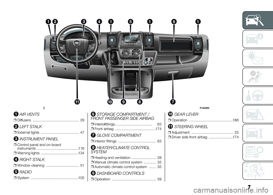
AIR VENTS
❒Diffusers ............................................. 29
LEFT STALK
❒External lights ..................................... 47
INSTRUMENT PANEL
❒Control panel and on-board
instruments .........................................116
❒Warning lights .....................................134
RIGHT STALK
❒Window cleaning ................................ 51
RADIO
❒System ...............................................105
STORAGE COMPARTMENT /
FRONT PASSENGER SIDE AIRBAG
❒Interiorfittings..................................... 63
❒Front airbag ........................................174
GLOVE COMPARTMENT
❒Interior fittings ..................................... 63
HEATER/CLIMATE CONTROL
SYSTEM
❒Heating and ventilation ........................ 28
❒Manual climate control system ............ 32
❒Automatic climate control system ....... 35
DASHBOARD CONTROLS
❒Operation ........................................... 59
GEAR LEVER
❒Operation ...........................................186
STEERING WHEEL
❒Adjustment ......................................... 25
❒Driver side front airbag ........................174
RADIO
MEDIA
PHONEINFO
A-B-C
MENU
123 4 56
3F1A5002
7
Page 14 of 387
RADIO.............................................105
ACCESSORIES PURCHASED BY
THE OWNER...................................106
REFUELLING THE VEHICLE ...........108
PROTECTING THE
ENVIRONMENT ..............................112
10
KNOW YOUR VEHICLE
Page 71 of 387
POWER SOCKET
(for versions/markets, where provided)
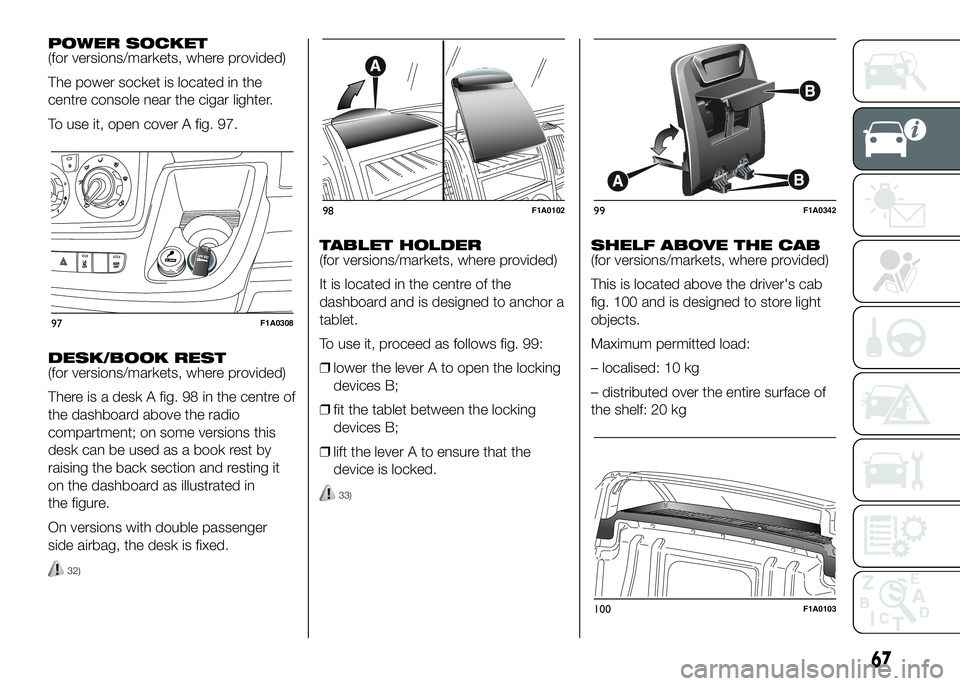
The power socket is located in the
centre console near the cigar lighter.
To use it, open cover A fig. 97.
DESK/BOOK REST
(for versions/markets, where provided)
There is a desk A fig. 98 in the centre of
the dashboard above the radio
compartment; on some versions this
desk can be used as a book rest by
raising the back section and resting it
on the dashboard as illustrated in
the figure.
On versions with double passenger
side airbag, the desk is fixed.
32)
TABLET HOLDER
(for versions/markets, where provided)
It is located in the centre of the
dashboard and is designed to anchor a
tablet.
To use it, proceed as follows fig. 99:
❒lower the lever A to open the locking
devices B;
❒fit the tablet between the locking
devices B;
❒lift the lever A to ensure that the
device is locked.
33)
SHELF ABOVE THE CAB
(for versions/markets, where provided)
This is located above the driver's cab
fig. 100 and is designed to store light
objects.
Maximum permitted load:
– localised: 10 kg
– distributed over the entire surface of
the shelf: 20 kg
97F1A0308
98F1A010299F1A0342
100F1A0103
67
Page 93 of 387
TPMS operation faults
The system fault is indicated by
warning light
which first flashes for
75 seconds and then stays on steadily.
This can occur in any of the following
situations:
❒interference caused by electronic
devices or radio frequency emissions
similar to those of the TPM sensors.
❒Application of tinted films which
interfere with the signals of the radio
waves.
❒Presence of snow or ice on the
wheels or the wheel arches.
❒Use of snow chains.
❒Use of wheels/tyres not equipped
with TPM sensors.
❒The space-saver wheel is not
equipped with the tyre pressure
control sensor. Therefore, the tyre
pressure is not controlled by the
system.
❒If the space-saver wheel replaces a
tyre with a pressure lower than the
insufficient pressure limit, an acoustic
signal will be emitted and the warning
light
will switch on at the next
ignition cycle.❒When the original tyre is repaired or
replaced and it is mounted back on
the vehicle to replace the space-
saver wheel, the TPMS will update
automatically and the warning light
will switch off, provided that the
pressure of none of the four tyres is
below the insufficient pressure limit.
You may need to drive the vehicle for
about 20 minutes at a speed higher
than 20 km/h to allow the TPMS
to receive this information.IMPORTANT
INFORMATION
WARNING
69) The TPMS is optimised for the
original tyres and wheels
provided. TPMS pressures and
alerts have been defined
according to the size of the tyres
mounted on the vehicle. Using
equipment with different size,
type or kind may cause irregular
system operation or sensor
damage. Non-original spare
wheels can damage the sensor.
Do not use tyre sealant or
balancing weights if the vehicle is
equipped with TPMS as these
may damage the sensors.
70) If the system signals a pressure
decrease on a specific tyre, it is
recommended to check the
pressure on all four tyres.
71) TPMS does not relieve the driver
from the obligation to check the
tyre pressure every month; it is
not even to be considered a
replacing system for maintenance
or a safety system.
89
Page 96 of 387
SYSTEM ACTIVATION/
DEACTIVATION
When the system is active, if the vehicle
gets close to one of the limit lines or
one of the two lane demarcation lines,
the driver is warned with an acoustic
signal (coming from the crossed line
side if the vehicle is equipped with the
radio navigation system) along with
the corresponding direction warning
light (
or) lighting up.
If the driver turns on the direction
indicator in order to change lanes or for
overtaking, then the system will switch
off the driver warning.
If the driver keeps deliberately with the
lane change manoeuvre, the system
interrupts the warning, remaining
enabled if the operating conditions are
not satisfied or active if the operating
conditions are exceeded (see the
dedicated paragraph).SWITCHING OFF THE
SYSTEM
Manual mode
The system can be switched off by
pressing button A fig. 128 on the
dashboard.
The LED on the button switches on and
a message appears on the display to
confirm that the system has been
switched off.
Automatic mode
If the Start&Stop is active the system
deactivates automatically. The system
will reactivate and check its operating
conditions again after the vehicle has
been started.
SYSTEM FAILURE
In the case of malfunction the system
signals the fault to the driver with a
message on the display, an acoustic
warning and switching on of the icon
on the display (for versions/markets,
where provided).IMPORTANT INFORMATION
The Driving Advisor cannot operate due
to a not perfectly balanced and
excessive load.
The operation of the system can be
adversely affected in some cases
by the morphology of the territory/road
being driven on (e.g. driving over
humps), poor visibility conditions (e.g.
fog, rain, snow), extreme light
conditions (e.g. glare of the sun,
darkness), lack of cleanliness
or damage, even partial, to the
windscreen in the area in front of the
camera.
The Driving Advisor cannot operate
following a malfunction of the following
safety systems: ABS, ESP, ASR and
Traction Plus.
The operation of the system can be
adversely affected by poor visibility
conditions (e.g. fog, rain, snow),
extreme light conditions (glare of the
sun, darkness), lack of cleaning or
damage, even partial, to the
windscreen in the area in front the
camera.
The area of the windscreen by the
camera must not be partly or totally
obscured by objects (e.g. stickers,
protective film, etc.).
92
KNOW YOUR VEHICLE
Page 110 of 387
System description
The vehicle is equipped with an UREA
fuel injection system and a Selective
Catalytic Reduction catalyst to meet the
emission standards.
These two systems ensure compliance
with the diesel emissions requirements;
at the same it maintains fuel saving
levels, driveability, torque and power.
For messages and system warnings
refer to "Knowing the instrument panel"
and "Warning lights and messages".
Remarks
❒When you stop the vehicle you could
hear a distinct click coming from
under the vehicle due to the UREA
injection system, this is normal.
❒The UREA injection system pump
continues to operate for a short
period of time after the engine is
switched off, to purge the circuit. This
is normal, and you can still hear its
noise from under the vehicle.RADIO
(for versions/markets, where provided)
For radio operation, consult the
Supplement attached to this Owner
Handbook.
SETUP
(for versions/markets, where provided)
The system consists of:
❒radio supply leads;
❒front speaker connection cables;
❒aerial supply lead;
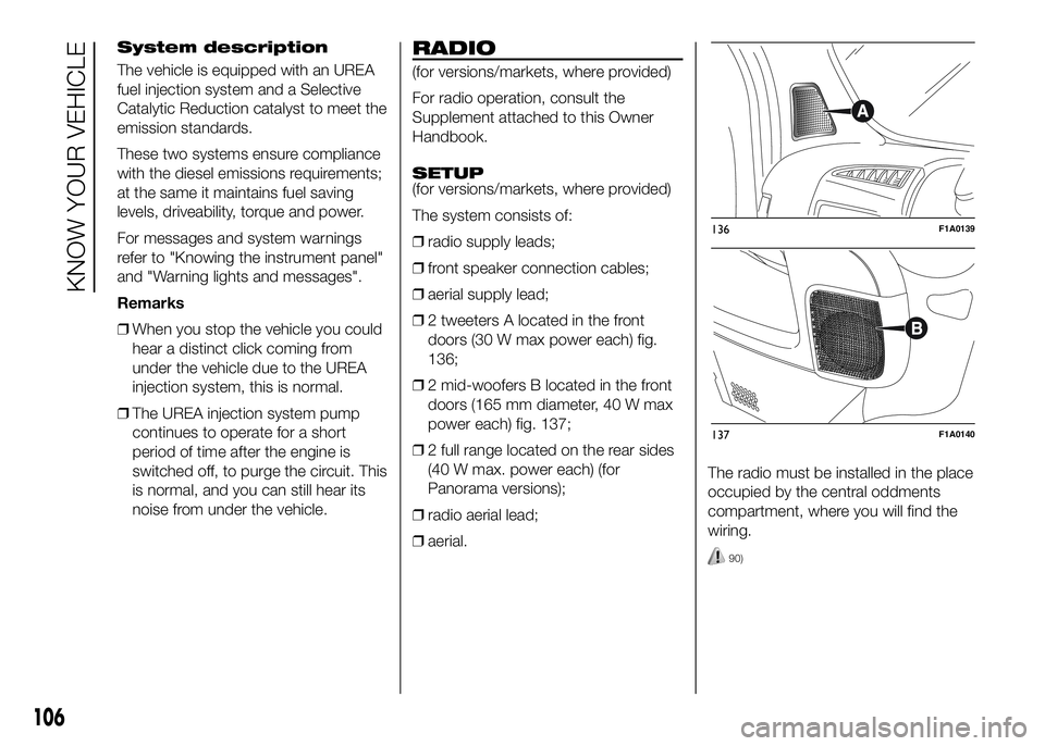
❒2 tweeters A located in the front
doors (30 W max power each) fig.
136;
❒2 mid-woofers B located in the front
doors (165 mm diameter, 40 W max
power each) fig. 137;
❒2 full range located on the rear sides
(40 W max. power each) (for
Panorama versions);
❒radio aerial lead;
❒aerial.The radio must be installed in the place
occupied by the central oddments
compartment, where you will find the
wiring.
90)
136F1A0139
137F1A0140
106
KNOW YOUR VEHICLE
Page 112 of 387
Fiat Auto S.p.A. shall not be liable for
damage caused by the installation
of accessories either not supplied or
recommended by Fiat Auto S.p.A.
and/or not installed in compliance with
the instructions provided.
RADIO TRANSMITTERS
AND MOBILE PHONES
Radio transmitter equipment (vehicle
mobile phones, CB radios, amateur
radio etc.) cannot be used inside the
car unless a separate aerial is mounted
externally.
IMPORTANT The use of these devices
inside the passenger compartment
(without an external aerial) may cause
the electrical systems to malfunction.
This could compromise the safety
of the car in addition to constituting a
potential hazard for passengers' health.
In addition, transmission and reception
of these devices may be affected by the
shielding effect of the car body.
As far as the use of EC-approved
mobile phones is concerned (GSM,
GPRS, UMTS), follow the usage
instructions provided by the mobile
phone manufacturer.PROVISION FOR FITTING
TELEPASS ON
REFLECTIVE
WINDSCREEN
(for versions/markets, where provided)
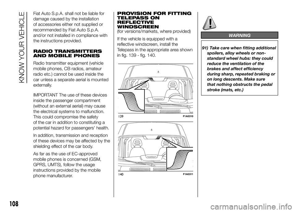
If the vehicle is equipped with a
reflective windscreen, install the
Telepass in the appropriate area shown
in fig. 139 - fig. 140.
WARNING
91) Take care when fitting additional
spoilers, alloy wheels or non-
standard wheel hubs: they could
reduce the ventilation of the
brakes and affect efficiency
during sharp, repeated braking or
on long descents. Make sure
that nothing obstructs the pedal
stroke (mats, etc.)
139F1A0310
140F1A0311
108
KNOW YOUR VEHICLE
Page 230 of 387
Dashboard fuse box
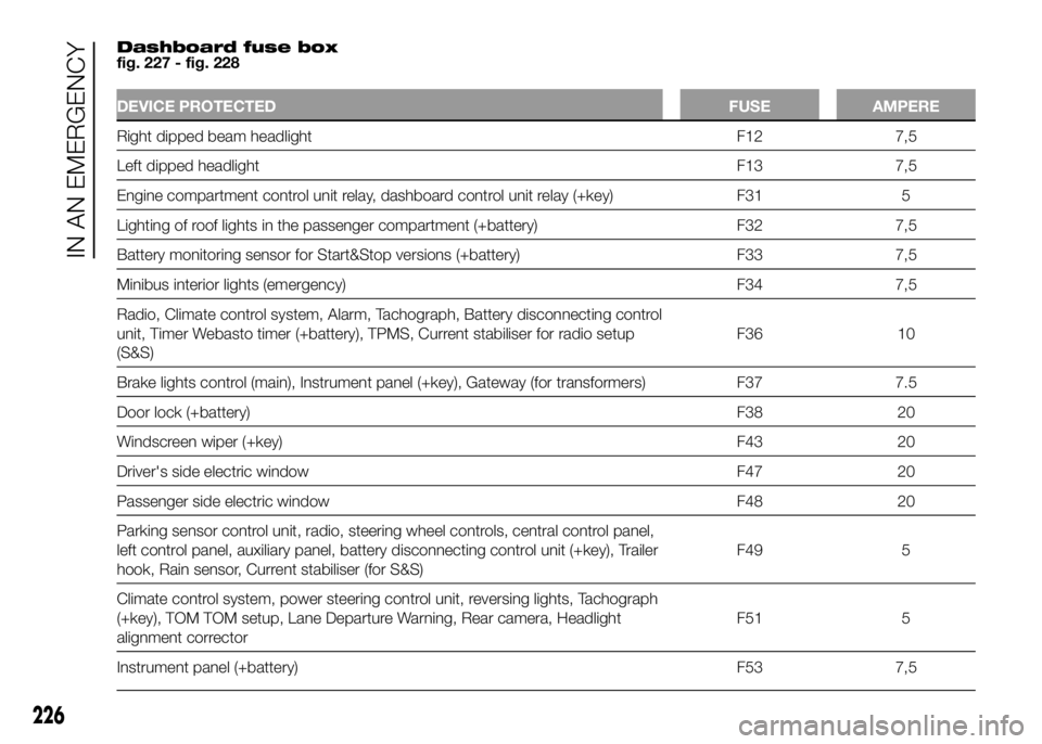
fig. 227 - fig. 228
DEVICE PROTECTED FUSE AMPERE
Right dipped beam headlight F12 7,5
Leftdipped headlight F13 7,5
Engine compartment control unit relay, dashboard control unit relay (+key) F31 5
Lighting of roof lights in the passenger compartment (+battery) F32 7,5
Battery monitoring sensor for Start&Stop versions (+battery) F33 7,5
Minibus interior lights (emergency) F34 7,5
Radio, Climate control system, Alarm, Tachograph, Battery disconnecting control
unit, Timer Webasto timer (+battery), TPMS, Current stabiliser for radio setup
(S&S)F36 10
Brake lights control (main), Instrument panel (+key), Gateway (for transformers) F37 7.5
Door lock (+battery) F38 20
Windscreen wiper (+key) F43 20
Driver's side electric window F47 20
Passenger side electric window F48 20
Parking sensor control unit, radio, steering wheel controls, central control panel,
left control panel, auxiliary panel, battery disconnecting control unit (+key), Trailer
hook, Rain sensor, Current stabiliser (for S&S)F49 5
Climate control system, power steering control unit, reversing lights, Tachograph
(+key), TOM TOM setup, Lane Departure Warning, Rear camera, Headlight
alignment correctorF51 5
Instrument panel (+battery) F53 7,5
226
IN AN EMERGENCY
Page 257 of 387
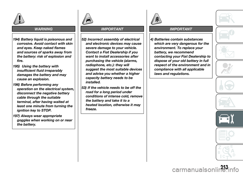
WARNING
194) Battery liquid is poisonous and
corrosive. Avoid contact with skin
and eyes. Keep naked flames
and sources of sparks away from
the battery: risk of explosion and
fire.
195) Using the battery with
insufficient fluid irreparably
damages the battery and may
cause an explosion.
196) Before performing any
operation on the electrical system,
disconnect the negative battery
cable through the suitable
terminal, after having waited at
least one minute from turning the
ignition key to STOP.
197) Always wear appropriate
goggles when working on or near
the battery.
IMPORTANT
52) Incorrect assembly of electrical
and electronic devices may cause
severe damage to your vehicle.
Contact a Fiat Dealership if you
want to install accessories after
purchasing the vehicle (alarms,
radiophone, etc.): they will
suggest the most suitable devices
and advise you whether a higher
capacity battery needs to be
installed.
53) If the vehicle needs to be off the
road for a long period under
conditions of intense cold, remove
the battery and take it to a
heated location, otherwise it may
freeze.
IMPORTANT
4) Batteries contain substances
which are very dangerous for the
environment. To replace your
battery, we recommend
contacting your Fiat Dealership to
dispose of your old battery in full
respect of the environment and in
compliance with all applicable
laws and regulations.
253
Page 385 of 387
Parking sensors ............................. 100
Performance .................................. 284
Pollen filter ..................................... 250
Power socket ................................. 67
Power steering fluid........................ 247
Power supply ................................. 267
Prescriptions for handling the
vehicle at the end of its life ........... 360
Pretensioners ................................. 161
Prolonged vehicle inactivity............. 199
Protecting the environment ............ 113
Radio ............................................ 106
Rain sensor .................................... 53
Rear camera .................................. 96
Rear door with two wings............... 74
Rear fog lights ................................ 60
Rear footboard ............................... 75
Rear partition ................................. 65
Rear roof light (changing a bulb) ..... 221
Rear view mirrors ........................... 25
Refrigerated compartment ............. 63
Refuelling the vehicle ...................... 109
Replacing an exterior bulb .............. 216
Replacing a wheel .......................... 203
Replacing the windscreen wiper
blades .......................................... 256
Rev counter ................................... 120
Revolving seat with seat belts ........ 18
Rim Protector................................. 271
Rims and tyres ............................... 270Roof lights...................................... 58
Roof rack ....................................... 79
Rubber hoses ................................ 255
Saving fuel .................................... 188
SBR system ................................... 161
Seat base plastic covers ................ 20
Seat belts
– Use ........................................... 160
Seats (Combi versions)................... 21
Seats ............................................. 16
Seats (Panorama version)............... 20
Seats with adjustable armrests....... 17
Seat with revolving base................. 18
Setup for Isofix child restraint
system ......................................... 168
Shelf above cab ............................. 67
Side bags....................................... 179
Side lights ......................... 48-217-221
Ski rack.......................................... 79
Sliding door.................................... 73
Sliding side window ....................... 73
Snow chains .................................. 198
Snow tyres ..................................... 198
Spare wheel ................................... 270
Speed block................................... 69
Speed Limiter................................. 56
Speedometer ................................. 120
Spray nozzles................................. 256
Sprung seat ................................... 17Starting the engine ................. 184-202
Start&Stop system ......................... 102
Steering ......................................... 269
Steering wheel ............................... 25
Stopping the engine ....................... 184
Sun visors ...................................... 66
Supplies ......................................... 327
Suspension .................................... 268
Symbols......................................... 11
Tablet Holder ................................ 67
Tachograph .................................... 68
third brake lights ............................ 220
Towing the vehicle .......................... 233
Towing trailers ................................ 190
TPMS............................................. 87
Traction Plus system ...................... 86
Transmission .................................. 268
Tray under the seat ........................ 19
Trip Computer ................................ 131
Tyres .............................................. 270
Upper storage compartment......... 63
Usage conditions ........................... 189
VIN plate ....................................... 262
Warming up the engine just
after it has started ........................ 184
Warning lights and messages......... 134
Weights.......................................... 286
Wheel geometry ............................. 270