rims FIAT DUCATO BASE CAMPER 2016 Owner handbook (in English)
[x] Cancel search | Manufacturer: FIAT, Model Year: 2016, Model line: DUCATO BASE CAMPER, Model: FIAT DUCATO BASE CAMPER 2016Pages: 387, PDF Size: 20.76 MB
Page 2 of 387
We really know your vehicle because we invented,
designed and built it: we really know every single detail. At Fiat Professional Service authorised workshops
you can find technicians directly trained by us, offering quality and professionalism for all service operations.
Fiat Professional workshops are always close to you for the regular servicing operations, season checks and practical recommendations by our experts.
With Fiat Professional Genuine Parts you keep the reliability, comfort and performance features of your new vehicle unchanged in time: that's why you bought it for.
Always ask for Genuine Parts for the components used on our vehicles; we recommend them because they come from our steady commitment in research and development of highly innovative technologies. For all these reasons: rely on Genuine Parts,
because they are the only ones designed by Fiat Professional for your vehicle.
SAFETY: BRAKING SYSTEMENVIRONMENT: PARTICULATE FILTERS,
CLIMATE CONTROL SYSTEM MAINTENANCECOMFORT:
SUSPENSION AND WINDSCREEN WIPERSPERFORMANCE:
SPARK PLUGS, INJECTORS AND BATTERIESLINEACCESSORI:
ROOF RACK BARS, WHEEL RIMS
WHY CHOOSING GENUINE PARTS
COP DUCATO LUM GB 10/06/15 09:29 Pagina 2
Page 9 of 387
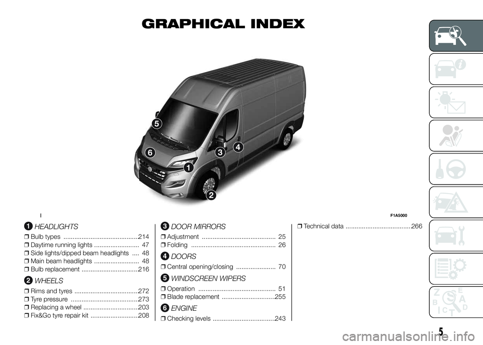
GRAPHICAL INDEX
.
HEADLIGHTS
❒Bulb types ..........................................214
❒Daytime running lights ......................... 47
❒Side lights/dipped beam headlights .... 48
❒Main beam headlights ......................... 48
❒Bulb replacement ................................216
WHEELS
❒Rims and tyres ....................................272
❒Tyre pressure ......................................273
❒Replacing a wheel ...............................203
❒Fix&Go tyre repair kit ...........................208
DOOR MIRRORS
❒Adjustment ......................................... 25
❒Folding ............................................... 26
DOORS
❒Central opening/closing ...................... 70
WINDSCREEN WIPERS
❒Operation ........................................... 51
❒Blade replacement ..............................255
ENGINE
❒Checking levels ...................................243❒Technical data .....................................266
1F1A5000
5
Page 92 of 387
The tyre pressure also increases while
driving the vehicle: this is a normal
condition and does not require any
adjustment of the pressure.
The TPMS continues to advise the
driver of the low tyre pressure condition
until this is corrected; the warning
continues until the pressure
corresponds or exceeds the pressure
prescribed for the cold tyres. When the
tyre low pressure control warning
light
switches on constantly, the
inflation pressure must be adjusted until
it reaches the pressure prescribed for
cold tyres. After the automatic update
of the system, the tyre pressure control
warning light switches off. You may
need to drive the vehicle for about 20
minutes at a speed higher than 20
km/h to allow the TPMS to receive this
information.
NOTE
❒The TPMS does not replace the
normal tyre maintenance service and
does not indicate any fault in a tyre.
❒Therefore, the TPMS should not be
used as pressure switch while
adjusting the tyre inflation pressure.❒Driving with insufficient tyre pressure
causes their overheating and can
result in tyre failure. The low inflation
pressure reduces fuel efficiency
and tyre tread life and may also affect
handling and braking performance
of the vehicle.
❒The TPMS does not replace the
correct tyre maintenance. It is up to
the driver to maintain the correct tyre
pressure level measuring it with a
suitable pressure switch. This is
necessary even if the decrease in the
inflation pressure value does not
cause the tyre pressure control
warning light to switch on.
❒The TPMS warns the driver of any
condition of insufficient tyre pressure
If this drops below the insufficient
pressure limit for any reason including
low temperature and normal
pressure loss of the tyre.
❒The seasonal temperature changes
affect tyre pressure.
The TPMS uses wireless devices with
electronic sensors mounted on the
wheel rims to constantly monitor the
value of tyre pressure. The sensors
mounted on each wheel as part of the
valve stem transmit various information
of the tyres to the receiver module, in
order to calculate the pressure.WARNING Monitoring and maintaining
the correct pressure in all four tyres
are particularly important.
Tyre pressure
monitoring system low
pressure warnings
The system warns the driver if one or
more tyres are flat by switching on
the warning light
on the instrument
panel (together with a warning message
and an acoustic signal).
In this case, stop the vehicle as soon as
possible, check the inflation pressure
of each tyre and inflate to the cold tyre
pressure value prescribed for the
vehicle. The system will automatically
update and after receiving the tyre
pressure update the tyre pressure
control warning light switches off. You
may need to drive the vehicle for about
20 minutes at a speed higher than 20
km/h to allow the system to receive this
information.
88
KNOW YOUR VEHICLE
Page 208 of 387
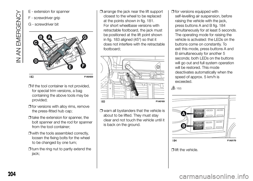
E - extension for spanner
F - screwdriver grip
G - screwdriver bit
❒if the tool container is not provided,
for special trim versions, a bag
containing the above tools may be
provided;
❒for versions with alloy rims, remove
the press-fitted hub cap;
❒take the extension for spanner, the
bolt spanner and the rod for spanner
from the tool container;
❒with the tools assembled correctly,
loosen the fixing bolts for the wheel
to be changed by one turn;
❒turn the ring nut to partly extend the
jack;❒arrange the jack near the lift support
closest to the wheel to be replaced
at the points shown in fig. 181.
For short wheelbase versions with
retractable footboard, the jack must
be positioned at the lift point shown
in fig. 183 aligned (45°) so that it
does not interfere with the retractable
footboard;
❒warn all bystanders that the vehicle is
about to be lifted. They must stay
clear and not touch the vehicle until it
is back on the ground.❒for versions equipped with
self-levelling air suspension, before
raising the vehicle with the jack,
press buttons A and B fig. 184
simultaneously for at least 5 seconds.
The operating mode for raising the
vehicle is activated: the LEDs on the
buttons come on constantly. To
exit this mode, press buttons A and
B simultaneously for another 5
seconds; both LEDs on the buttons
will go out and full system operation
will be restored. This mode
deactivates automatically when the
speed of approx. 5 km/h is
exceeded.
152)
❒lift the vehicle.
182F1A0420
183F1A0169
184F1A0170
204
IN AN EMERGENCY
Page 210 of 387
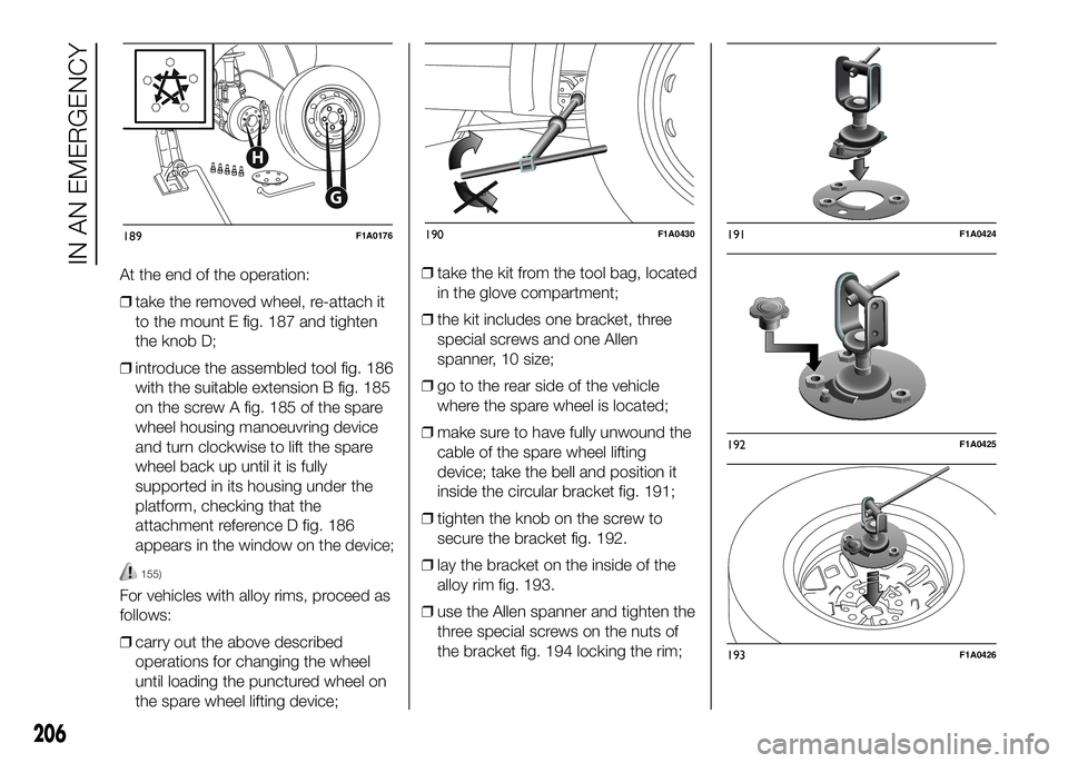
At the end of the operation:
❒take the removed wheel, re-attach it
to the mount E fig. 187 and tighten
the knob D;
❒introduce the assembled tool fig. 186
with the suitable extension B fig. 185
on the screw A fig. 185 of the spare
wheel housing manoeuvring device
and turn clockwise to lift the spare
wheel back up until it is fully
supported in its housing under the
platform, checking that the
attachment reference D fig. 186
appears in the window on the device;
155)
For vehicles with alloy rims, proceed as
follows:
❒carry out the above described
operations for changing the wheel
until loading the punctured wheel on
the spare wheel lifting device;❒take the kit from the tool bag, located
in the glove compartment;
❒the kit includes one bracket, three
special screws and one Allen
spanner, 10 size;
❒go to the rear side of the vehicle
where the spare wheel is located;
❒make sure to have fully unwound the
cable of the spare wheel lifting
device; take the bell and position it
inside the circular bracket fig. 191;
❒tighten the knob on the screw to
secure the bracket fig. 192.
❒lay the bracket on the inside of the
alloy rim fig. 193.
❒use the Allen spanner and tighten the
three special screws on the nuts of
the bracket fig. 194 locking the rim;
G
H
189F1A0176190F1A0430191F1A0424
192F1A0425
193F1A0426
206
IN AN EMERGENCY
Page 259 of 387
WARNING
198) Remember that the road
holding qualities of your vehicle
also depend on the correct
inflation pressure of the tyres.
199) If the pressure is too low, the
tyre will overheat and could be
seriously damaged.
200) Avoid switching the tyres from
the right side of the vehicle to the
left side and vice versa.
201) Never submit alloy rims to
repainting treatments requiring
the use of temperatures
exceeding 150°C. The mechanical
properties of the wheels could
be impaired.
RUBBER HOSES
As far as the brake system and fuel
supply system rubber hoses are
concerned, follow the "Scheduled
Servicing Plan" in this chapter carefully.
Ozone, high temperatures and
prolonged lack of fluid in the system
may cause hardening and cracking of
the hoses, with possible leaks. Careful
checking is therefore necessary.
WINDSCREEN
WIPER
BLADES
Periodically clean the rubber part using
special products; TUTELA
PROFESSIONAL SC 35 is
recommended.
Replace the blades if the rubber edge is
deformed or worn. In any case, it is
advisable to replace them
approximately once a year.
A few simple precautions can reduce
the possibility of damage to the blades:
❒if the temperature falls below zero,
make sure that ice has not frozen
the rubber against the glass. Use a
de-icing product to release it if
required;
❒remove any snow from the glass: in
addition to protecting the blades,
this prevents effort on the motor and
overheating;
❒do not operate the windscreen and
rear window wipers on dry glass.
202)
255
Page 274 of 387
WHEELS
RIMS AND TYRES
Pressed steel or alloy rims. Tubeless
radial carcass tyres. All approved tyres
are listed in the registration document.
IMPORTANT If there are any
discrepancies between the "Owner
Handbook" and the "Registration
document", take the information from
the latter.
To ensure driving safety, ensure that
tyres of the same make and type are
fitted on all wheels.
IMPORTANT Do not use air chambers
with tubeless tyres.
SPARE WHEEL
Pressed steel rim. Tubeless tyre.
WHEEL GEOMETRY
Front wheel toe-in measured from rim
to rim: -1±1mm.
The values refer to the vehicle in
running order.CORRECT READING OF
THE TYRE
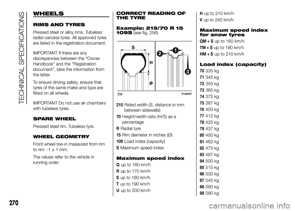
Example: 215/70 R 15
109S(see fig. 256)
215Rated width (S, distance in mm
between sidewalls)
70Height/width ratio (H/S) as a
percentage
RRadial tyre
15Rim diameter in inches (Ø)
109Load index (capacity)
SMaximum speed index
Maximum speed index
Qup to 160 km/h
Rup to 170 km/h
Sup to 180 km/h
Tup to 190 km/h
Uup to 200 km/h
Hup to 210 km/h
Vup to 240 km/h
Maximum speed index
for snow tyres
QM+Sup to 160 km/h
TM+Sup to 190 km/h
HM+Sup to 210 km/h
Load index (capacity)
70335 kg
71345 kg
72355 kg
73365 kg
74375 kg
75387 kg
76400 kg
77412 kg
78425 kg
79437 kg
80450 kg
81462 kg
82475 kg
83487 kg
84500 kg
85515 kg
86530 kg
87545 kg
88560 kg
89580 kg
256F1A0247
270
TECHNICAL SPECIFICATIONS
Page 276 of 387
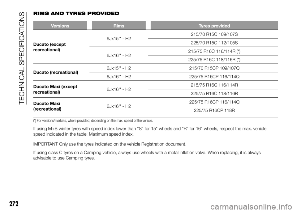
RIMS AND TYRES PROVIDED
Versions Rims Tyres provided
Ducato (except
r
ecreational)6Jx15'' - H2215/70 R15C 109/107S
225/70 R15C 112/105S
6Jx16'' - H2215/75 R16C 116/114R (*)
225/75 R16C 118/116R (*)
Ducato (recreational)6Jx15'' - H2 215/70 R15CP 109/107Q
6Jx16'' - H2 225/75 R16CP 116/114Q
Ducato Maxi (except
recreational)6Jx16'' - H2215/75 R16C 116/114R
225/75 R16C 118/116R
Ducato Maxi
(recreational)6Jx16'' - H2225/75 R16CP 116/114Q
225/75 R16CP 118R
(*) For versions/markets, where provided, depending on the max. speed of the vehicle..
If using M+S winter tyres with speed index lower than “S” for 15" wheels and “R” for 16" wheels, respect the max. vehicle
speed indicated in the table: Maximum speed index.
IMPORTANT Only use the tyres indicated on the vehicle Registration document.
If using class C tyres on a Camping vehicle, always use wheels with a metal inflation valve. When replacing, it is always
advisable to use Camping tyres.
272
TECHNICAL SPECIFICATIONS
Page 385 of 387
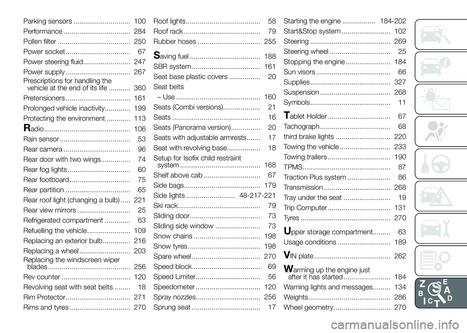
Parking sensors ............................. 100
Performance .................................. 284
Pollen filter ..................................... 250
Power socket ................................. 67
Power steering fluid........................ 247
Power supply ................................. 267
Prescriptions for handling the
vehicle at the end of its life ........... 360
Pretensioners ................................. 161
Prolonged vehicle inactivity............. 199
Protecting the environment ............ 113
Radio ............................................ 106
Rain sensor .................................... 53
Rear camera .................................. 96
Rear door with two wings............... 74
Rear fog lights ................................ 60
Rear footboard ............................... 75
Rear partition ................................. 65
Rear roof light (changing a bulb) ..... 221
Rear view mirrors ........................... 25
Refrigerated compartment ............. 63
Refuelling the vehicle ...................... 109
Replacing an exterior bulb .............. 216
Replacing a wheel .......................... 203
Replacing the windscreen wiper
blades .......................................... 256
Rev counter ................................... 120
Revolving seat with seat belts ........ 18
Rim Protector................................. 271
Rims and tyres ............................... 270Roof lights...................................... 58
Roof rack ....................................... 79
Rubber hoses ................................ 255
Saving fuel .................................... 188
SBR system ................................... 161
Seat base plastic covers ................ 20
Seat belts
– Use ........................................... 160
Seats (Combi versions)................... 21
Seats ............................................. 16
Seats (Panorama version)............... 20
Seats with adjustable armrests....... 17
Seat with revolving base................. 18
Setup for Isofix child restraint
system ......................................... 168
Shelf above cab ............................. 67
Side bags....................................... 179
Side lights ......................... 48-217-221
Ski rack.......................................... 79
Sliding door.................................... 73
Sliding side window ....................... 73
Snow chains .................................. 198
Snow tyres ..................................... 198
Spare wheel ................................... 270
Speed block................................... 69
Speed Limiter................................. 56
Speedometer ................................. 120
Spray nozzles................................. 256
Sprung seat ................................... 17Starting the engine ................. 184-202
Start&Stop system ......................... 102
Steering ......................................... 269
Steering wheel ............................... 25
Stopping the engine ....................... 184
Sun visors ...................................... 66
Supplies ......................................... 327
Suspension .................................... 268
Symbols......................................... 11
Tablet Holder ................................ 67
Tachograph .................................... 68
third brake lights ............................ 220
Towing the vehicle .......................... 233
Towing trailers ................................ 190
TPMS............................................. 87
Traction Plus system ...................... 86
Transmission .................................. 268
Tray under the seat ........................ 19
Trip Computer ................................ 131
Tyres .............................................. 270
Upper storage compartment......... 63
Usage conditions ........................... 189
VIN plate ....................................... 262
Warming up the engine just
after it has started ........................ 184
Warning lights and messages......... 134
Weights.......................................... 286
Wheel geometry ............................. 270