technical data FIAT DUCATO BASE CAMPER 2016 Owner handbook (in English)
[x] Cancel search | Manufacturer: FIAT, Model Year: 2016, Model line: DUCATO BASE CAMPER, Model: FIAT DUCATO BASE CAMPER 2016Pages: 387, PDF Size: 20.76 MB
Page 5 of 387
Dear Customer,
We would like to congratulate and thank you for choosing a Fiat Ducato. We have written this handbook to help you get to know all the
features of your vehicle and use it in the best possible way. You should read it right through before taking to the road for the first time.
You will find information, tips and important warnings regarding the use of your vehicle to help you get the most from the technological features
of your Fiat Ducato. It also provides a description of special features and essential information for the care and maintenance of your vehicle
over time as well as for safe driving.
We urge you to read the warnings and indications found throughout the text with care, marked with the following symbols:
personal safety;
vehicle integrity;
environmental protection.
NOTE These symbols, when necessary, are reported at the end of each paragraph and are followed by a number. That number recalls the
corresponding warning at the end of the relevant section.
In the attached Warranty Booklet you will also find a description of the Services that Fiat offers to its customers, the Warranty Certificate and
the detail of the terms and conditions for maintaining its validity.
We are sure that these will help you to get in touch with and appreciate your new vehicle and the service provided by the people at Fiat.
Enjoy reading. Happy motoring!
This Owner Handbook describes all Fiat Ducato versions. As a consequence, you should only consider the information
which is related to the trim level, engine and version that you have purchased. All data contained in this publication are
purely indicative. FCA Italy S.p.A. can modify the specifications of the vehicle model described in this publication at any
time, for technical or marketing purposes. For further information, contact a Fiat Dealership.
Page 9 of 387
GRAPHICAL INDEX
.
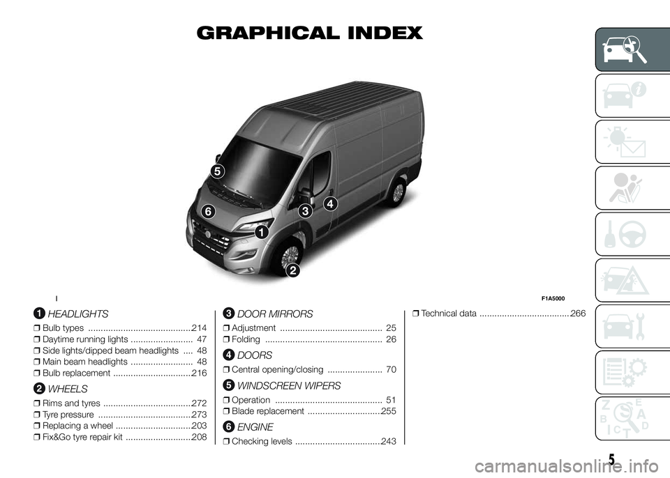
HEADLIGHTS
❒Bulb types ..........................................214
❒Daytime running lights ......................... 47
❒Side lights/dipped beam headlights .... 48
❒Main beam headlights ......................... 48
❒Bulb replacement ................................216
WHEELS
❒Rims and tyres ....................................272
❒Tyre pressure ......................................273
❒Replacing a wheel ...............................203
❒Fix&Go tyre repair kit ...........................208
DOOR MIRRORS
❒Adjustment ......................................... 25
❒Folding ............................................... 26
DOORS
❒Central opening/closing ...................... 70
WINDSCREEN WIPERS
❒Operation ........................................... 51
❒Blade replacement ..............................255
ENGINE
❒Checking levels ...................................243❒Technical data .....................................266
1F1A5000
5
Page 115 of 387
❒if during the topping up, the level of
AdBlue in the bottle does not drop,
it means that you have reached
the full tank, therefore proceed pulling
the bottle towards you in order to
re-lock the safety valve of the bottle
and unscrew the bottle from the
filler (fig. 142, ref. 3);
❒after removing the bottle remount
cap C fig. 141 on the filler neck
UREA, turning it clockwise until it
stops;
❒turn the key in the pawl starter in the
ON position (no need to start the
engine);
❒wait for the signal on the instrument
panel to power off before moving the
vehicle, the warning light may stay
on for a few seconds to half a
minute. In case of motor start-up and
movement of the vehicle, the
warning sign will remain on for a
longer period of time, but there are
no problems on the engine
functionality;
❒If topping up is done with the UREA
tank empty, you have to wait two
minutes before starting the vehicle;NoteThe driving conditions (altitude,
vehicle speed, load, etc.) determine the
quantity of UREA used by the vehicle.
In order to use the additive for Diesel
Emissions (UREA) correctly, see "Fluids
and lubricants" in the "Technical data".
IMPORTANT
❒Exceeding the maximum filling
level of the tank UREA, it can
cause damage to the tank and
spilling UREA. Please avoid
topping up after filling the tank.
❒DO NOT EXCEED THE MAXIMUM
LEVEL. The UREA freezes at
under -11 ° C. Although the
system is designed to operate
below the freezing point of the
UREA, it is advisable not to fill the
tank beyond the maximum level
because if the UREA freezes
the system can be damaged.
❒If the UREA is spilled on painted
surfaces or aluminium,
immediately clean the area with
water and use absorbent material
to collect the fluid that has been
spilled on the ground.
❒Do not try to start the engine if
UREA was accidentally added
to the diesel fuel tank, this can
result in serious engine damage,
contact Dealership.❒Use AdBlue only according to DIN
70 070 and ISO 22241-1. Other
fluids may cause damage to the
system: also exhaust emissions
would no longer comply with
the law. The distribution
companies are responsible for
the compliance of their product.
Observe the precautions of
storage and maintenance, in
order to preserve the initial
qualities. The manufacturer of the
vehicle does not recognize any
guarantee in case of
malfunctions and damage caused
to the vehicle due to the use of
urea (AdBlue) not in accordance
with regulations.
❒Any introduction of diesel fuel
inside the tank AdBlue, causes
irreversible damage to the
pumping unit circuit AdBlue.
❒Do not add additives to AdBlue.
Do not dilute AdBlue with tap
water as this may damage the
system of purification of exhaust
gases.
111
Page 191 of 387
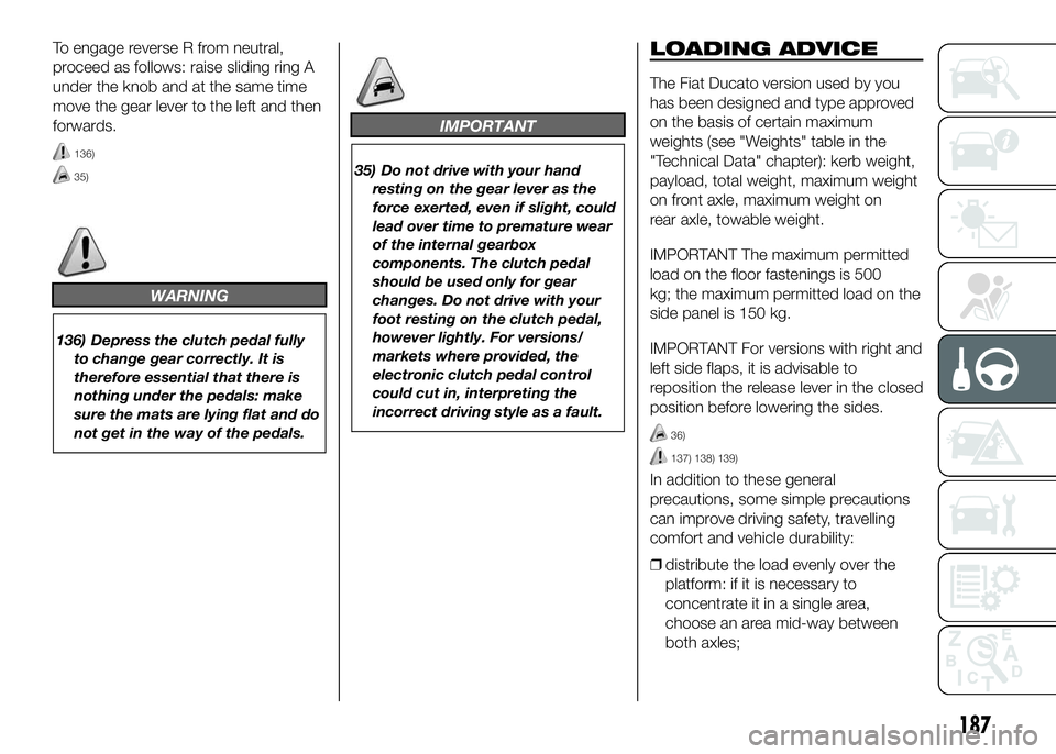
To engage reverse R from neutral,
proceed as follows: raise sliding ring A
under the knob and at the same time
move the gear lever to the left and then
forwards.
136)
35)
WARNING
136) Depress the clutch pedal fully
to change gear correctly. It is
therefore essential that there is
nothing under the pedals: make
sure the mats are lying flat and do
not get in the way of the pedals.
IMPORTANT
35) Do not drive with your hand
resting on the gear lever as the
force exerted, even if slight, could
lead over time to premature wear
of the internal gearbox
components. The clutch pedal
should be used only for gear
changes. Do not drive with your
foot resting on the clutch pedal,
however lightly. For versions/
markets where provided, the
electronic clutch pedal control
could cut in, interpreting the
incorrect driving style as a fault.
LOADING ADVICE
The Fiat Ducato version used by you
has been designed and type approved
on the basis of certain maximum
weights (see "Weights" table in the
"Technical Data" chapter): kerb weight,
payload, total weight, maximum weight
on front axle, maximum weight on
rear axle, towable weight.
IMPORTANT The maximum permitted
load on the floor fastenings is 500
kg; the maximum permitted load on the
side panel is 150 kg.
IMPORTANT For versions with right and
left side flaps, it is advisable to
reposition the release lever in the closed
position before lowering the sides.
36)
137) 138) 139)
In addition to these general
precautions, some simple precautions
can improve driving safety, travelling
comfort and vehicle durability:
❒distribute the load evenly over the
platform: if it is necessary to
concentrate it in a single area,
choose an area mid-way between
both axles;
187
Page 195 of 387
For the electric connection a standard
connector should be used which is
generally placed on a special bracket
normally fastened to the towing device,
and a special ECU for external trailer
light control must be installed on the
vehicle. For the electrical connection, 7
or 13 pin 12 V DC connections are to
be used (CUNA/UNI and ISO/DIN
Standards). Follow the instructions
provided by the vehicle manufacturer
and/or the tow hitch manufacturer.
An electric brake (or electric winch)
should be supplied directly by the
battery through a cable with a cross
section of no less than 2.5 mm
2.
IMPORTANT Electric brakes or other
devices must be used with engine
running.
In addition to the electrical branches,
the vehicle's electric system can only
be connected to the supply cable for an
electric brake and to the cable for an
internal light, though not above 15
W. For connections use the preset
control unit with battery cable no less
than 2.5 mm
2.IMPORTANT The trailer tow hook
contributes to the length of the vehicle.
When installing on long wheelbase
versions, it is only possible to install
removable tow hooks because the total
vehicle length limit of 6 metres is
exceeded.
If no trailer is fitted, the hook must be
removed from the attachment base and
it must not exceed the vehicle's
original length.
IMPORTANT If you wish to leave the
tow hook fitted without towing a trailer,
it is advisable to contact a Fiat
Dealership for the relevant system
update operations because the tow
hook could be detected as an obstacle
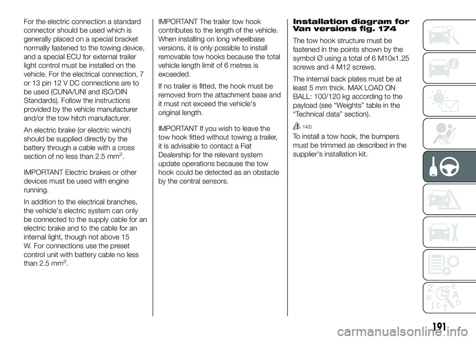
by the central sensors.Installation diagram for
Van versions fig. 174
The tow hook structure must be
fastened in the points shown by the
symbol Ø using a total of 6 M10x1.25
screws and 4 M12 screws.
The internal back plates must be at
least 5 mm thick. MAX LOAD ON
BALL: 100/120 kg according to the
payload (see “Weights” table in the
“Technical data” section).
142)
To install a tow hook, the bumpers
must be trimmed as described in the
supplier's installation kit.
191
Page 196 of 387
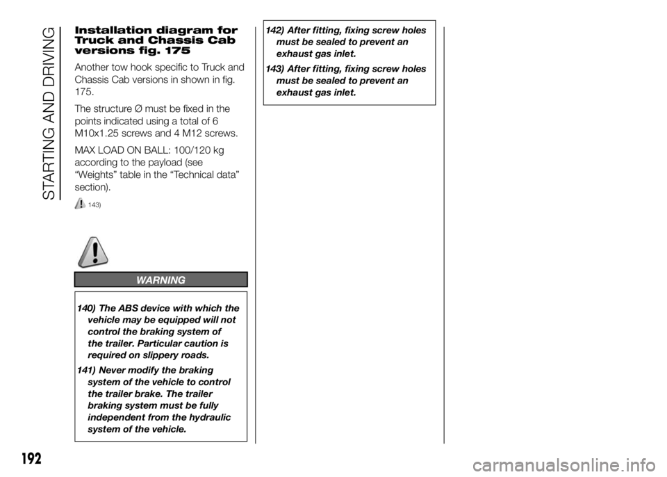
Installation diagram for
Truck and Chassis Cab
versions fig. 175
Another tow hook specific to Truck and
Chassis Cab versions in shown in fig.
175.
The structure Ø must be fixed in the
points indicated using a total of 6
M10x1.25 screws and 4 M12 screws.
MAX LOAD ON BALL: 100/120 kg
according to the payload (see
“Weights” table in the “Technical data”
section).
143)
WARNING
140) The ABS device with which the
vehicle may be equipped will not
control the braking system of
the trailer. Particular caution is
required on slippery roads.
141) Never modify the braking
system of the vehicle to control
the trailer brake. The trailer
braking system must be fully
independent from the hydraulic
system of the vehicle.142) After fitting, fixing screw holes
must be sealed to prevent an
exhaust gas inlet.
143) After fitting, fixing screw holes
must be sealed to prevent an
exhaust gas inlet.
192
STARTING AND DRIVING
Page 213 of 387
❒instruction brochure (see fig. 196), to
be used for prompt and correct use
of the quick tyre repair kit and then to
be handed to the personnel charged
with handling the tyre treated with
the tyre repair kit;
❒a compressor D complete with
pressure gauge and connectors;
❒a pair of protective gloves located in
the side compartment of the
compressor;
❒adaptors for inflating different
elements.
158) 159) 160)
44)
IMPORTANT
INFORMATION:
The sealing fluid of the quick tyre repair
kit is effective at external temperatures
of between -20 °C and +50 °C.
The sealant has an expiry date.
161) 162)
2)
INFLATION PROCEDURE
163) 164) 165) 166) 167)
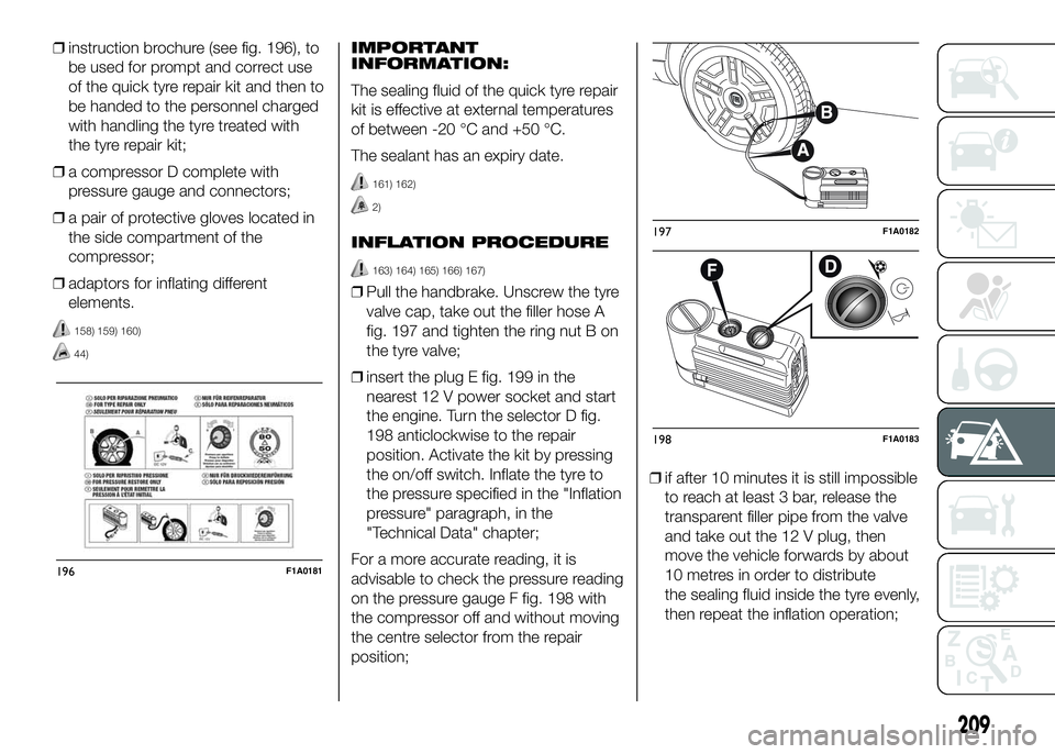
❒Pull the handbrake. Unscrew the tyre
valve cap, take out the filler hose A
fig. 197 and tighten the ring nut B on
the tyre valve;
❒insert the plug E fig. 199 in the
nearest 12 V power socket and start
the engine. Turn the selector D fig.
198 anticlockwise to the repair
position. Activate the kit by pressing
the on/off switch. Inflate the tyre to
the pressure specified in the "Inflation
pressure" paragraph, in the
"Technical Data" chapter;
For a more accurate reading, it is
advisable to check the pressure reading
on the pressure gauge F fig. 198 with
the compressor off and without moving
the centre selector from the repair
position;❒if after 10 minutes it is still impossible
to reach at least 3 bar, release the
transparent filler pipe from the valve
and take out the 12 V plug, then
move the vehicle forwards by about
10 metres in order to distribute
the sealing fluid inside the tyre evenly,
then repeat the inflation operation;
196F1A0181
197F1A0182
198F1A0183
209
Page 214 of 387
❒if after this operation you still cannot
reach at least 3 bar after 10 minutes,
do not resume driving because the
tyre is too damaged and the quick
tyre repair kit cannot guarantee
suitable sealing. Contact a Fiat
Dealership;
❒if the tyre reaches the pressure
specified in “Inflation pressure”
paragraph in the "Technical Data"
section, start driving immediately;
❒after having driven for about
10 minutes, stop and recheck the
tyre pressure; remember to apply the
handbrake;❒if a pressure value of at least 3 bar is
detected, restore the correct
pressure prescribed in the paragraph
“Inflation pressure” in “Technical
specification” (with the engine
running and the handbrake
engaged), resume driving and drive
with care to nearest Fiat Dealership.
FOR CHECKING AND
RESTORING PRESSURE
ONLY
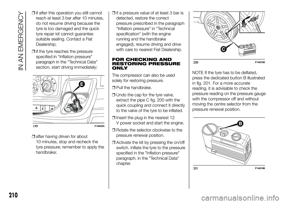
The compressor can also be used
solely for restoring pressure.
❒Pull the handbrake.
❒Undo the cap for the tyre valve,
extract the pipe C fig. 200 with the
quick coupling and connect it directly
to the valve of the tyre to be inflated.
❒Insert the plug in the nearest 12
V power socket and start the engine.
❒Rotate the selector clockwise to the
pressure renewal position.
❒Activate the kit by pressing the on/off
switch. Inflate the tyre to the pressure
specified in the "Inflation pressure"
paragraph, in the "Technical Data"
chapter.NOTE If the tyre has to be deflated,
press the dedicated button B illustrated
in fig. 201. For a more accurate
reading, it is advisable to check the
pressure reading on the pressure gauge
with the compressor off and without
moving the centre selector from the
pressure renewal position.
199F1A0335
200F1A0185
201F1A0186
210
IN AN EMERGENCY
Page 265 of 387
TECHNICAL SPECIFICATIONS
Everything you may find useful for
understanding how your vehicle
is made and works is contained in this
chapter and illustrated with data, tables
and graphics. For the enthusiasts and
the technician, but also just for those
who want to know every detail of their
vehicle.IDENTIFICATION DATA....................262
ENGINE CODES - BODYWORK
VERSION ........................................264
ENGINE ..........................................266
POWER SUPPLY ............................267
TRANSMISSION .............................268
SUSPENSION .................................268
BRAKES .........................................269
STEERING ......................................269
WHEELS .........................................270
DIMENSIONS ..................................274
PERFORMANCE .............................284
WEIGHTS........................................286
SUPPLIES .......................................327
FLUIDS AND LUBRICANTS ............329
FUEL CONSUMPTION ....................333
CO2 EMISSIONS ............................345
OFFICIAL TYPE APPROVALS .........356
PRESCRIPTIONS FOR HANDLING
THE VEHICLE AT THE END OF ITS
LIFE ................................................360
261
Page 266 of 387
IDENTIFICATION
DATA
It is advisable to take note of the
identification codes. Identification codes
are printed and shown on the plates
as indicated below, together with the
positions:
❒VIN plate.
❒Chassis marking.
❒Bodywork paint identification plate.
❒Engine marking.
V.I.N. PLATE
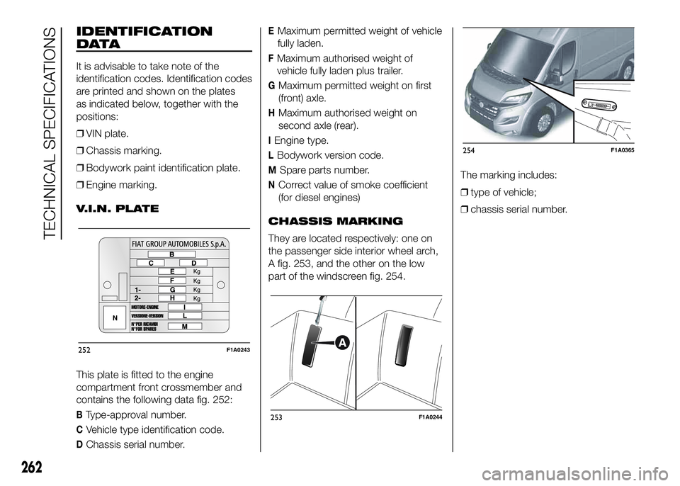
This plate is fitted to the engine
compartment front crossmember and
contains the following data fig. 252:
BType-approval number.
CVehicle type identification code.
DChassis serial number.
EMaximum permitted weight of vehicle
fully laden.
FMaximum authorised weight of
vehicle fully laden plus trailer.
GMaximum permitted weight on first
(front) axle.
HMaximum authorised weight on
second axle (rear).
IEngine type.
LBodywork version code.
MSpare parts number.
NCorrect value of smoke coefficient
(for diesel engines)
CHASSIS MARKING
They are located respectively: one on
the passenger side interior wheel arch,
A fig. 253, and the other on the low
part of the windscreen fig. 254.The marking includes:
❒type of vehicle;
❒chassis serial number.
252F1A0243
253F1A0244
254F1A0365
262
TECHNICAL SPECIFICATIONS