headlights FIAT DUCATO BASE CAMPER 2017 Owner handbook (in English)
[x] Cancel search | Manufacturer: FIAT, Model Year: 2017, Model line: DUCATO BASE CAMPER, Model: FIAT DUCATO BASE CAMPER 2017Pages: 296, PDF Size: 14.44 MB
Page 73 of 296
 What it means What to do
greenDIPPED BEAM HEADLIGHTS
The warning light switches on when the dipped beam
headlights are turned on.
FOLLOW ME HOME
The warning light switches on (together with a
message")
What it means What to do
greenDIPPED BEAM HEADLIGHTS
The warning light switches on when the dipped beam
headlights are turned on.
FOLLOW ME HOME
The warning light switches on (together with a
message shown on the display) when this device is in
use (see "Follow me home device" paragraph in
"Exterior lights" in the "Knowing your vehicle" chapter).
greenLEFT DIRECTION INDICATOR
The warning light switches on when the direction
indicator control stalk is moved downwards or,
together with the right direction indicator, when the
hazard warning light button is pressed.
greenRIGHT DIRECTION INDICATOR
The warning light switches on when the direction
indicator control stalk is moved upwards or, together
with the left direction indicator, when the hazard
warning light button is pressed.
71
Page 74 of 296
 What it means What to do
greenFOG LIGHTS
The warning light comes on when the front fog lights
are turned on.
greenCRUISE CONTROL
(for versions/markets, where provided)
On turning the key to the MAR po")
What it means What to do
greenFOG LIGHTS
The warning light comes on when the front fog lights
are turned on.
greenCRUISE CONTROL
(for versions/markets, where provided)
On turning the key to the MAR position, the warning
light on the display turns on, but it must turn off after a
few seconds if the Cruise Control is disabled.
The warning light is lit up on the display by turning the
Cruise Control selector wheel to ON or, according
to the versions. On certain versions a dedicated
message is displayed.
greenSPEED LIMITER
(for versions/markets, where provided)
The warning light on the dial switches on when the
function is activated.
On certain versions a dedicated message is displayed.
greenAUTOMATIC MAIN BEAM HEADLIGHTS
This warning light comes on when the automatic main
beam headlights are activated.
blueMAIN BEAM HEADLIGHTS
The warning light switches on when the main beam
headlights are turned on.
72
KNOWING THE INSTRUMENT PANEL
Page 76 of 296
 Messages on display
What it means What to do
EXTERIOR LIGHTS FAILURE
(Versions with reconfigurable multifunction display)
The symbol switches on when a fault is detected on
one of the following lights")
Messages on display
What it means What to do
EXTERIOR LIGHTS FAILURE
(Versions with reconfigurable multifunction display)
The symbol switches on when a fault is detected on
one of the following lights:
direction indicators
rear fog lights
brake lights
side lights
daytime running lights
number plate lights
reversing lights
main beam automatism
trailer side lights
trailer direction indicators.The fault relating to these lights could be: one or more
blown bulbs, a blown protection fuse or a break in the
electrical connection.
LOW ENGINE OIL PRESSURE WARNING LIGHT
FAILURE
The symbol turns on to indicate a failure of the low
engine oil pressure warning light.Contact a Fiat Dealership.
BRAKE LIGHTS FAILURE
(Versions with reconfigurable multifunction display)
The symbol switches on when a fault is detected in the
brake lights.The fault could be: one or more blown bulbs, a blown
protection fuse or a break in the electrical connection.
MAIN BEAM AUTOMATISM FAULT
(Versions with reconfigurable multifunction display)
The symbol switches on when a fault is detected in the
automatic switching-on system for the main beam
headlights.
74
KNOWING THE INSTRUMENT PANEL
Page 127 of 296
 WARNING
124)If the camera loses its position due to
a load variation, the system may not work
temporarily to allow the camera to perform
an auto-calibration.
125)The system only detects the preset
tra")
WARNING
124)If the camera loses its position due to
a load variation, the system may not work
temporarily to allow the camera to perform
an auto-calibration.
125)The system only detects the preset
traffic signs. If the minimum visibility
conditions and distance from the sign are
met it can detect all traffic signs.
126)The system is a driving assistance
system but it does not relieve the driver of
the responsibility of driving with due
attention and diligence in compliance with
the laws in force.
127)When the system is active, the driver
is responsible for controlling the vehicle
and monitoring the system, and must
intervene as appropriate if necessary.
WARNING
27)In the event of errors the system may
not work.
28)At low temperatures and in particularly
adverse weather conditions, the system
may not work.
29)Rain, snow, splashes and strong light
contrast may influence the sensor.
30)Do not repair the area of the
windscreen directly surrounding the sensor.
31)If the vehicle is equipped with a
non-genuine suspension kit, the system
may not work correctly.
32)Always use genuine spare parts when
replacing the bulbs of the headlights. Other
bulbs may reduce the system
performance.
33)Clean the windscreen from foreign
matters such as bird droppings, insects,
snow or ice.
REFUELLING THE
VEHICLE
IN BRIEF
Stop the engine before refuelling.
PETROL ENGINES
Only use petrol with an octane number
(RON) no lower than 95 (EN228
specification).
DIESEL ENGINES
Refuel the vehicle exclusively with diesel
for motor vehicles in compliance with
European specification EN590.
OPERATION AT LOW
TEMPERATURES
When using or parking the vehicle for a
long time in the mountains or cold
areas, it is advisable to refuel using
locally available diesel fuel. In this case,
it is also advisable to keep the tank
over 50% full.
34)
100
115F1A0373
125
Page 145 of 296
 REPLACING A BULB
GENERAL
INSTRUCTIONS
139) 140)
46)
When a light is not working, check
that the corresponding fuse is intact
before changing a bulb. For the location
of fuses, refer to the paragraph
&")
REPLACING A BULB
GENERAL
INSTRUCTIONS
139) 140)
46)
When a light is not working, check
that the corresponding fuse is intact
before changing a bulb. For the location
of fuses, refer to the paragraph
"Replacing fuses" in this chapter.
before changing a bulb check the
contacts for oxidation;
burnt bulbs must be replaced by
others of the same type and power;
always check the headlight beam
direction after changing a bulb;
IMPORTANT A slight misting may
appear on the internal surface of the
headlight: this does not indicate a fault
and is caused by low temperature
and the degree of humidity in the air.
Misting will rapidly disappear when the
headlights are switched on. The
presence of drops inside the headlights
indicates infiltration of water. Contact
a Fiat Dealership.
WARNING
139)Modifications or repairs to the
electric system that are not carried out
properly or do not take the system
technical specifications into account can
cause malfunctions leading to the risk
of fire.
140)Halogen bulbs contain pressurised
gas, in the case of breakage they may
burst causing glass fragments to be
projected outwards.
WARNING
46)Halogen bulbs must be handled
holding the metallic part only. Touching the
transparent part of the bulb with your
fingers may reduce the intensity of the
emitted light and even reduce the lifespan
of the bulb. In the event of accidental
contact, wipe the bulb with a cloth
moistened with alcohol and let the bulb
dry.
143
Page 147 of 296
 Light bulbs
 Type Power Figure ref.
Main beam headlights H7 55W D
Dipped beam headlights H7 55W D
Front side lights / daytime running lights
W21/5W - LED
(#)--
Front fog lights
(*)H11 55W -")
Light bulbs
Light bulbs Type Power Figure ref.
Main beam headlights H7 55W D
Dipped beam headlights H7 55W D
Front side lights / daytime running lights
W21/5W - LED
(#)--
Front fog lights
(*)H11 55W -
Front direction indicators WY21W 21W B
Side turn lightW16WF
(**) / WY5W
(***)16W(**) / 5W (***)A
Rear direction indicators PY2IW 21W B
Side lights W5W 5W A
Rear side lights P21/5W 21/5W B
Rear side lights/Brake lights P21W 21W B
Third brake light W5W 5W B
Reverse gear W16W 16W B
Rear fog light W16W 16W B
Number plate C5W 5W A
Front roof light (movable lens) 12V10W 10W C
Rear ceiling light 12V10W 10W C
(#) where provided, instead of bulb W21/5W
(*)for versions/markets, where provided
(**)XL and Tempo Libero versions
(***)all other versions
145
Page 148 of 296
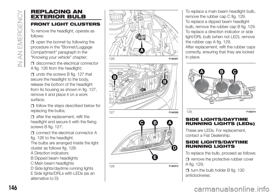
REPLACING AN
EXTERIOR BULB
FRONT LIGHT CLUSTERS
To remove the headlight, operate as
follows:
open the bonnet by following the
procedure in the "Bonnet/Luggage
Compartment" paragraph in the
"Knowing your vehicle" chapter;
disconnect the electrical connector
A fig. 126 from the headlight;
undo the screws B fig. 127 that
secure the headlight to the body,
release the bottom of the headlight
from its housing as shown in fig. 127,
remove it and place it on a work
surface;
follow the steps described below for
replacing the bulbs;
after the replacement, refit the
headlight and secure it with the fixing
screws B fig. 127;
connect the electrical connector A
fig. 126 to the headlight.
The bulbs are arranged inside the light
cluster as follows fig. 128:
A Direction indicators
B Dipped beam headlights
C Main beam headlights
D Side lights/daytime running lights
E Side lights/DRLs with LEDs (as an
alternative to D)To replace a main beam headlight bulb,
remove the rubber cap C fig. 129.
To replace a dipped beam headlight
bulb, remove the rubber cap B fig. 129.
To replace a direction indicator or side
light/DRL bulb (when not LED), remove
the rubber cap A fig. 129.
After replacement, refit the rubber caps
correctly, ensuring that they are locked
in place.
SIDE LIGHTS/DAYTIME
RUNNING LIGHTS (LEDs)
These are LEDs. For replacement,
contact a Fiat Dealership.
SIDE LIGHTS/DAYTIME
RUNNING LIGHTS
To replace the bulb, proceed as follows:
remove the protective rubber cover
A fig. 129;
turn the bulb holder B fig. 130
anticlockwise;
126F1A0337
127F1A0338
128F1A0313
129F1A0314
146
IN AN EMERGENCY
Page 149 of 296
 extract the bulb by pulling and
replace it;
remove the bulb by pushing it
slightly and turning it anticlockwise
(bayonet mount);
refit the bulb holder B by turning it
clockwise and making sure that it")
extract the bulb by pulling and
replace it;
remove the bulb by pushing it
slightly and turning it anticlockwise
(bayonet mount);
refit the bulb holder B by turning it
clockwise and making sure that it locks
correctly
refit the protective rubber cover A
fig. 129.
MAIN BEAM HEADLIGHTSTo replace the bulb, proceed as follows:
remove the protective rubber cover
C fig. 129;
free the bulb holder A fig. 131 from
the side clips B and remove it;
disconnect the electrical connector;
fit the new bulb, ensuring that the
outline of the metal part coincides with
the grooves on the curve of the
headlight, pressing to engage it with the
side clips;
reconnect the electrical connector;
refit the protective rubber cover
C fig. 129.
DIPPED BEAM
HEADLIGHTS
With incandescent bulbs
To replace the bulb, proceed as follows:
remove the protective rubber cover
B fig. 129;
free the bulb holder A fig. 132 from
the side clips B and remove it;
disconnect the electrical connector;
fit the new bulb, ensuring that the
outline of the metal part coincides with
the grooves on the curve of the
headlight, pressing to engage it with the
side clips;
reconnect the electrical connector;
refit the protective rubber cover
B fig. 129.
DIRECTION INDICATORS
To replace the bulb, proceed as follows:
remove the protective rubber cover
A fig. 129;
turn the bulb holder B fig. 133
anticlockwise;
extract the bulb by pulling and
replace it;
remove the bulb by pushing it
slightly and turning it anticlockwise
(bayonet mount);
refit the bulb holder B by turning it
clockwise and making sure that it locks
correctly
refit the protective rubber cover A
fig. 129.
130F1A0386
131F1A0315
132F1A0316
147
Page 181 of 296
 VERSIONS WITH
START&STOP SYSTEM
To recharge, proceed as follows:
disconnect the connector A
(pressing the button B) from the sensor
C monitoring the battery conditions,
on the negative pole D of the b")
VERSIONS WITH
START&STOP SYSTEM
To recharge, proceed as follows:
disconnect the connector A
(pressing the button B) from the sensor
C monitoring the battery conditions,
on the negative pole D of the battery;
connect the positive battery charger
lead to the positive battery terminal E
and the negative lead to the sensor
terminal F as in fig. 178;
turn on the charger;
at the end of the charging process,
switch the battery charger off;
after disconnecting the charger,
reconnect the connector A to the
sensor C as in fig. 178.
WARNING
168)Battery fluid is poisonous and
corrosive: avoid contact with your skin and
eyes. The battery should be charged in a
well ventilated place, away from naked
flames or possible sources of sparks:
danger of explosion and fire.
169)Do not attempt to charge a frozen
battery: it must be thawed first, otherwise it
may explode. If freezing has occurred, the
battery should be checked by skilled
personnel to make sure that the internal
elements are not damaged and that the
body is not cracked, with the risk of leaking
poisonous and corrosive acid.
FUEL CUT-OFF
SWITCH
The vehicle is fitted with a safety switch
that, in the event of a crash, comes
into operation by cutting off the fuel
supply and turning off the engine as a
consequence.
When the inertia switch cuts in, it cuts
off the fuel supply and also activates
the hazard warning lights, side lights
and courtesy lights while releasing
all the doors and displaying the relevant
message; they are deactivated by
pressing button A. On some versions,
there is also a safety relay that activates
in the event of impact to cut off the
electrical supply. In this way, fuel is
prevented from escaping if the pipes
are broken and the formation of sparks
or electrical discharges following
damage to the vehicle electrical
components is avoided.
170) 171)
IMPORTANT After an accident,
remember to remove the key from the
ignition device to prevent the battery
from running down. If no fuel leaks
or damage to vehicle's electrical
devices (e.g. headlights) are detected
after the impact and the vehicle is
able to set off again, reactivate the
automatic fuel cut-off switch.
178F1A0219
179
Page 182 of 296
 Restoring the fuel cut-off switch
Press button A fig. 179 to reactivate the
fuel cut off switch.
WARNING
170)If, after an impact, you smell fuel or
notice leaks from the fuel system, do
not reactivate")
Restoring the fuel cut-off switch
Press button A fig. 179 to reactivate the
fuel cut off switch.
WARNING
170)If, after an impact, you smell fuel or
notice leaks from the fuel system, do
not reactivate the switch to avoid the risk
of fire.
171)Before reactivating the fuel cut-off
switch, carefully check for fuel leaks or
damage to the vehicle's electrical devices
(e.g. headlights).
TOWING THE
VEHICLE
172) 173) 174) 175) 176) 177) 178) 179) 180)
The vehicle is equipped with two rings
for attaching the tow hook.
The front ring is located in the tool box
beneath the passenger side seat. On
versions with Fix&Go kit and without
spare wheel, the tool box is available
only on request for versions/markets
where provided.In the absence of the tool box the
vehicle front tow hook is housed in the
on-board documentation container,
together with the Owner Handbook.
To use it, proceed as follows:
Open the flap A and remove it as
illustrated in fig. 180;
turn retaining knob B fig. 180
anticlockwise and remove it to allow the
box fig. 181 to come out;
179F1A0086
180F1A0221
181F1A0222
182F1A0344
183F1A0223
180
IN AN EMERGENCY