stop start FIAT DUCATO BASE CAMPER 2017 Owner handbook (in English)
[x] Cancel search | Manufacturer: FIAT, Model Year: 2017, Model line: DUCATO BASE CAMPER, Model: FIAT DUCATO BASE CAMPER 2017Pages: 296, PDF Size: 14.44 MB
Page 92 of 296
vehicle direction getting constantly
closer to the lane demarcation lines (the
vehicle trajectory is within the lane
demarcation lines);
vehicle not constantly next to the
lane demarcation line.
ACTIVATING/
DEACTIVATING THE
SYSTEM
When the system is active, if the vehicle
gets close to one of the side
demarcation lines or one of the two
lane demarcation lines, the driver is
warned with an acoustic signal (coming
from the crossed line side if the vehicle
is equipped with the radio navigation
system) along with the corresponding
direction warning light (
or) lighting
up.
If the driver turns on the direction
indicator in order to change lanes or for
overtaking, then the system will switch
off the driver warning.
If the driver keeps deliberately with the
lane change manoeuvre, the system
interrupts the warning, remaining
enabled if the operating conditions are
not satisfied or active if the operating
conditions are exceeded (see the
dedicated paragraph).SWITCHING OFF THE
SYSTEM
Manual mode
The system can be switched off by
pressing button A fig. 85 on the
dashboard.
The LED on the button switches on and
a message appears on the display to
confirm that the system has been
switched off.
Automatic mode
If the Start&Stop is active the system
deactivates automatically. The system
will reactivate and check its operating
conditions again after the vehicle has
been started.
SYSTEM FAILURE
In the event of malfunction, the system
signals the fault to the driver with a
message on the display, an acoustic
warning and by turning on the
icon
on the display (for versions/markets,
where provided).
IMPORTANT NOTES
The Driving Advisor cannot operate due
to a not perfectly balanced and
excessive load.The operation of the system can be
adversely affected in some cases
by the morphology of the territory/road
being driven on (e.g. driving over
humps), poor visibility conditions (e.g.
fog, rain, snow), extreme light
conditions (e.g. glare of the sun,
darkness), lack of cleanliness
or damage, even partial, to the
windscreen in the area in front of the
camera.
The Driving Advisor cannot operate
following a malfunction of the following
safety systems: ABS, ESC, ASR and
Traction Plus.
The operation of the system can be
adversely affected by poor visibility
conditions (e.g. fog, rain, snow),
extreme light conditions (glare of the
sun, darkness), lack of cleaning or
damage, even partial, to the
windscreen in the area in front the
camera.
The area of the windscreen by the
camera must not be partly or totally
obscured by objects (e.g. stickers,
protective film, etc.).
90
SAFETY
Page 116 of 296
STARTING AND DRIVING
Let’s get to the "heart" of the vehicle:
seeing how you can exploit all of its
potential to the full.
We’ll look at how to drive it safely in any
situation, so that it can be a welcome
companion, with our comfort and
our wallets in mind.STARTING THE ENGINE .................115
WHEN PARKED ..............................116
MANUAL TRANSMISSION ..............117
COMFORT-MATIC GEARBOX .........117
START&STOP SYSTEM ..................119
CRUISE CONTROL (CONSTANT
SPEED REGULATOR) .....................119
SPEED BLOCK ...............................121
PARKING SENSORS.......................122
REAR CAMERA (PARKVIEW®
REAR BACK UP CAMERA) .............123
TRAFFIC SIGN RECOGNITION .......124
REFUELLING THE VEHICLE ...........125
ADDITIVE FOR DIESEL EMISSIONS
ADBLUE (UREA)..............................130
VERSION WITH METHANE
SYSTEM (NATURAL POWER) .........131
LOADING ADVICE...........................133
SAVING FUEL .................................134
TOWING TRAILERS ........................135
PROLONGED VEHICLE
INACTIVITY .....................................141
114
STARTING AND DRIVING
Page 118 of 296
16)If the engine fails to start with a gear
engaged, the potentially dangerous
situation due to the fact that the
transmission is automatically placed in
neutral will be signalled by a buzzer.
17)If the warning light
flashes for 60
seconds after starting or during an
extended towing period, this indicates a
problem in the glow plug preheating
system. Use the vehicle normally if the
engine starts, but contact a Fiat Dealership
as soon as possible.
18)Remember that the brake servo and
power steering are not operational until the
engine has been started, so you need to
apply much more force than usual to
the brake pedal and steering wheel.
19)Never bump start the engine by
pushing, towing or coasting downhill. This
could cause fuel to flow into the catalytic
converter and damage it beyond repair.
20)A quick burst on the accelerator before
stopping the engine serves no practical
purpose; it wastes fuel and is especially
damaging to turbocharged engines.
21)In some cases, when the engine
switches off, the fan could activate for max.
120 seconds.
WHEN PARKED
116)
22)
Proceed as follows when parking and
leaving the vehicle:
engage the gear (on a slope, engage
first gear if the vehicle is facing uphill
or reverse if it is facing downhill) and
leave the wheels steered;
stop the engine and engage the
handbrake;
always remove the ignition key.
If the vehicle is parked on a steep
slope, it is advisable to block the
wheels with a wedge or stone.
On versions equipped with automatic
transmission (Comfort matic), wait
for the letterPto appear on the display
before releasing the brake pedal.
IMPORTANTNEVERleave the vehicle
with the gearbox in neutral (or, on
versions equipped with automatic
(Comfort matic) transmission, before
putting the shift lever in thePposition).HANDBRAKE
Handbrake engagement:The
handbrake lever is located to the left of
the driver's seat. Pull the lever upwards
to engage the handbrake and ensure
that the vehicle does not move.
Handbrake disengagement:slightly
raise the lever, hold the button A
pressed and check that the
warning light switches off on the
instrument panel.
Press the brake pedal when carrying
out this operation to prevent the vehicle
from moving accidentally.
WARNING
116)Never leave children unattended in
the vehicle. Always remove the ignition key
when leaving the vehicle and take it out
with you.
WARNING
22)If the vehicle is equipped with
self-levelling air suspension, always check
that there is sufficient space above the roof
and around the vehicle when parking.
Indeed, the vehicle could raise (or lower)
automatically depending on load or
temperature changes.
116
STARTING AND DRIVING
Page 121 of 296
START&STOP
SYSTEM
IN BRIEF
The Start&Stop device automatically
stops the engine each time the
vehicle is stationary and all the
conditions for automatic switch-off
have been met, and starts it again
when the driver wants to move off.
This improves the efficiency of the
vehicle by reducing fuel consumption,
the emission of harmful gases and
noise pollution.
OPERATING MODE
Stopping the engine
Versions with mechanical gearbox
With the vehicle stationary, the engine
stops with the gearbox in neutral and
the clutch pedal released.
Restarting the engine
Versions with mechanical gearbox
Depress the clutch pedal to restart
the engine.MANUAL ACTIVATION
AND DEACTIVATION OF
THE SYSTEM
To activate/deactivate the system
manually, press the
button on the
dashboard control panel.
24)
118) 119)
WARNING
24)If the vehicle is equipped with manual
climate control, if you want to favour
climate comfort, the Start&Stop system
can be deactivated for continuous climate
control system operation.
WARNING
118)The vehicle should always be
evacuated after the key has been removed
or turned to the STOP position. When
refuelling, make sure that the car is
switched off with the key in the STOP
position.
119)If the battery needs to be replaced,
always contact a Fiat Dealership. The
replacement battery should be of the same
type (L6 105Ah/850A) and should have
the same characteristics.
CRUISE CONTROL
(constant speed
regulator)
(for versions/markets, where provided)
IN BRIEF
This is an electronic driving aid that
allows you to drive at a speed of
above 30 km/h on long and straight
dry roads with few driving changes
(e.g. motorways) at a preset speed
without having to press the
accelerator pedal. It is therefore not
recommended to use this device
on extra-urban roads with traffic. Do
not use the device in town.
Turning the device on
Turn the ring A fig. 110 - fig. 111 to the
ON position or
(depending on the
version).
The Cruise Control cannot be engaged
in 1st or reverse gear. It is advisable
to engage it in 4th or higher gears.
When travelling downhill with the device
engaged, the vehicle speed may
slightly exceed the stored one.
119
Page 124 of 296
PARKING SENSORS
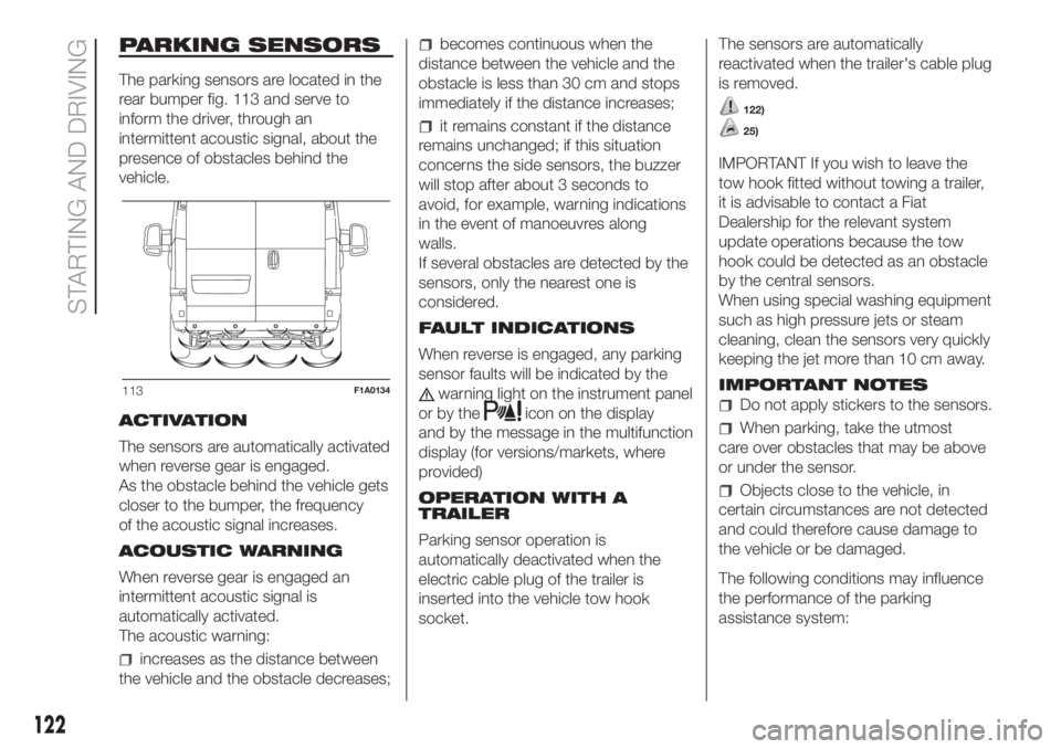
The parking sensors are located in the
rear bumper fig. 113 and serve to
inform the driver, through an
intermittent acoustic signal, about the
presence of obstacles behind the
vehicle.
ACTIVATION
The sensors are automatically activated
when reverse gear is engaged.
As the obstacle behind the vehicle gets
closer to the bumper, the frequency
of the acoustic signal increases.
ACOUSTIC WARNING
When reverse gear is engaged an
intermittent acoustic signal is
automatically activated.
The acoustic warning:
increases as the distance between
the vehicle and the obstacle decreases;
becomes continuous when the
distance between the vehicle and the
obstacle is less than 30 cm and stops
immediately if the distance increases;
it remains constant if the distance
remains unchanged; if this situation
concerns the side sensors, the buzzer
will stop after about 3 seconds to
avoid, for example, warning indications
in the event of manoeuvres along
walls.
If several obstacles are detected by the
sensors, only the nearest one is
considered.
FAULT INDICATIONS
When reverse is engaged, any parking
sensor faults will be indicated by the
warning light on the instrument panel
or by the
icon on the display
and by the message in the multifunction
display (for versions/markets, where
provided)
OPERATION WITH A
TRAILER
Parking sensor operation is
automatically deactivated when the
electric cable plug of the trailer is
inserted into the vehicle tow hook
socket.The sensors are automatically
reactivated when the trailer's cable plug
is removed.
122)
25)
IMPORTANT If you wish to leave the
tow hook fitted without towing a trailer,
it is advisable to contact a Fiat
Dealership for the relevant system
update operations because the tow
hook could be detected as an obstacle
by the central sensors.
When using special washing equipment
such as high pressure jets or steam
cleaning, clean the sensors very quickly
keeping the jet more than 10 cm away.
IMPORTANT NOTES
Do not apply stickers to the sensors.
When parking, take the utmost
care over obstacles that may be above
or under the sensor.
Objects close to the vehicle, in
certain circumstances are not detected
and could therefore cause damage to
the vehicle or be damaged.
The following conditions may influence
the performance of the parking
assistance system:
113F1A0134
122
STARTING AND DRIVING
Page 128 of 296
TANK CAPACITY
To ensure that you fill the tank
completely, top up twice after the first
click of the fuel supply gun. Further
top-ups could cause faults in the fuel
feeding system.
FUEL TANK CAP
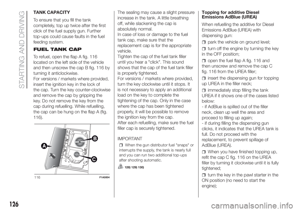
To refuel, open the flap A fig. 116
located on the left side of the vehicle
and then unscrew the cap B fig. 116 by
turning it anticlockwise.
For versions / markets where provided,
insert the ignition key in the lock of
the cap. Turn the key counter-clockwise
and remove the cap by gripping the
key. Do not remove the key from the
cap during refuelling. While refuelling,
the cap can be hung on the flap A (fig.
116).The sealing may cause a slight pressure
increase in the tank. A little breathing
off, while slackening the cap is
absolutely normal.
In case of loss or damage to the fuel
tank cap, make sure that the
replacement cap is for the appropriate
vehicle.
Tighten the cap of the fuel tank filler
until you hear a "click". This sound
shows that the cap of the fuel tank filler
is properly tightened.
For versions / markets where provided,
turn the key clockwise until it stops. It
is not necessary to apply an additional
load on the key to complete the
tightening of the cap. Only in the case
where the cap has been tightened
properly, it will be possible to remove
the ignition key from the cap.
After each refuelling, make sure the fuel
filler cap is securely tightened.
IMPORTANT
When the gun distributor fuel "snaps" or
interrupts the supply, the tank is nearly full
and you can run two additional top-ups
after shooting automatic.
128) 129) 130)
Topping for additive Diesel
Emissions AdBlue (UREA)
When refuelling the additive for Diesel
Emissions AdBlue (UREA) with
dispensing gun:
park the vehicle on ground level;
turn off the engine by turning the key
in the OFF position;
open the fuel flap A fig. 116 and
then unscrew and remove the cap C
fig. 116 from the UREA filler;
insert the dispensing gun for topping
up UREA in the filler neck;
immediately stop filling the tank
UREA if it shows one of the cases listed
below:
- if AdBlue is spilled out of the filler
neck, clean up well the area and
proceed to filling up again;
- if during filling the dispensing gun
clicks, it indicates that the UREA tank is
full. Do not proceed with the
replacement, to prevent spillage of
AdBlue (UREA).
When you have finished topping up,
refit the cap C fig. 116 on the UREA
filler by turning it clockwise until it is fully
tightened;
turn the key in the pawl starter in the
ON position (no need to start the
engine);116F1A5004
126
STARTING AND DRIVING
Page 136 of 296
SAVING FUEL
GENERAL INFORMATION
The general factors that affect fuel
consumption are listed below.
Vehicle maintenance
Tyres
Unnecessary loads
Roof rack/ski rack
Electric devices
Climate control system
Devices for aerodynamic control
DRIVING STYLE
The main driving styles that affect fuel
consumption are listed below.
Starting
Do not warm up the engine at low or
high revs when the vehicle is stationary;
this causes the engine to warm up
more slowly, thereby increasing fuel
consumption and emissions.
Unnecessary actions
Avoid accelerating when stopped at
traffic lights or before switching off the
engine.Gear selection
In the same way improper use of a high
gear increases consumption, emissions
and engine wear.
Top speed
Fuel consumption increases
considerably with speed.
Acceleration
Accelerating violently will greatly affect
consumption and emissions:
acceleration should be gradual.
CONDITIONS OF USE
The main usage conditions that
negatively affect fuel consumption are
listed below.
Cold starting
Short journeys and frequent cold starts
do not allow the engine to reach
optimum operating temperature.
Traffic and road conditions
Rather high consumption levels are
linked to situations with heavy traffic, for
instance when travelling in queues
with frequent use of the lower gears or
in cities with many traffic lights. Winding
mountain roads and rough road
surfaces also adversely affect
consumption.Stops in traffic
During prolonged hold-ups (e.g. level
crossings) the engine should be
switched off.
134
STARTING AND DRIVING
Page 142 of 296
Please note that the tow bar can be
installed only when in these conditions.
If the locking mechanism of the tow
bar is disengaged before the
installation, or at any other time, and is
in the locked position, it must be
pre-loaded. The locked position can be
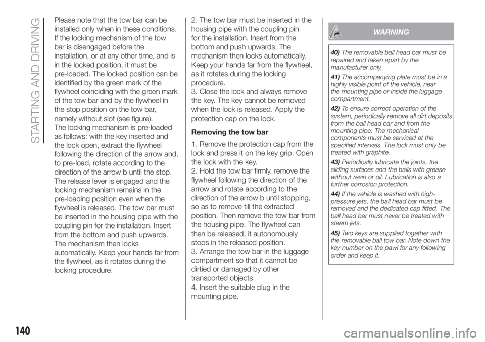
identified by the green mark of the
flywheel coinciding with the green mark
of the tow bar and by the flywheel in
the stop position on the tow bar,
namely without slot (see figure).
The locking mechanism is pre-loaded
as follows: with the key inserted and
the lock open, extract the flywheel
following the direction of the arrow and,
to pre-load, rotate according to the
direction of the arrow b until the stop.
The release lever is engaged and the
locking mechanism remains in the
pre-loading position even when the
flywheel is released. The tow bar must
be inserted in the housing pipe with the
coupling pin for the installation. Insert
from the bottom and push upwards.
The mechanism then locks
automatically. Keep your hands far from
the flywheel, as it rotates during the
locking procedure.2. The tow bar must be inserted in the
housing pipe with the coupling pin
for the installation. Insert from the
bottom and push upwards. The
mechanism then locks automatically.
Keep your hands far from the flywheel,
as it rotates during the locking
procedure.
3. Close the lock and always remove
the key. The key cannot be removed
when the lock is released. Apply the
protection cap on the lock.
Removing the tow bar
1. Remove the protection cap from the
lock and press it on the key grip. Open
the lock with the key.
2. Hold the tow bar firmly, remove the
flywheel following the direction of the
arrow and rotate according to the
direction of the arrow b until stopping,
so as to remove till the extracted
position. Then remove the tow bar from
the housing pipe. The flywheel can
then be released; it autonomously
stops in the released position.
3. Arrange the tow bar in the luggage
compartment so that it cannot be
dirtied or damaged by other
transported objects.
4. Insert the suitable plug in the
mounting pipe.
WARNING
40)The removable ball head bar must be
repaired and taken apart by the
manufacturer only.
41)The accompanying plate must be in a
highly visible point of the vehicle, near
the mounting pipe or inside the luggage
compartment.
42)To ensure correct operation of the
system, periodically remove all dirt deposits
from the ball head bar and from the
mounting pipe. The mechanical
components must be serviced at the
specified intervals. The lock must only be
treated with graphite.
43)Periodically lubricate the joints, the
sliding surfaces and the balls with grease
without resin or oil. Lubrication is also a
further corrosion protection.
44)If the vehicle is washed with high-
pressure jets, the ball head bar must be
removed and the dedicated cap fitted. The
ball head bar must never be treated with
steam jets.
45)Two keys are supplied together with
the removable ball tow bar. Note down the
key number on the pawl for any following
order and keep it.
140
STARTING AND DRIVING
Page 157 of 296
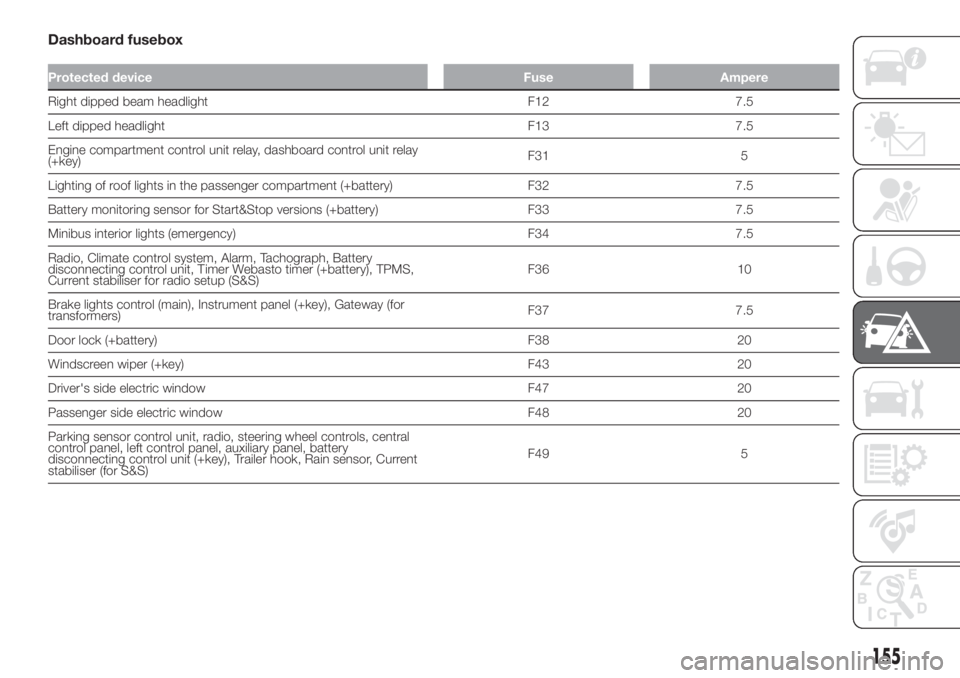
Dashboard fusebox
Protected device Fuse Ampere
Right dipped beam headlight F12 7.5
Left dipped headlight F13 7.5
Engine compartment control unit relay, dashboard control unit relay
(+key)F31 5
Lighting of roof lights in the passenger compartment (+battery) F32 7.5
Battery monitoring sensor for Start&Stop versions (+battery) F33 7.5
Minibus interior lights (emergency) F34 7.5
Radio, Climate control system, Alarm, Tachograph, Battery
disconnecting control unit, Timer Webasto timer (+battery), TPMS,
Current stabiliser for radio setup (S&S)F36 10
Brake lights control (main), Instrument panel (+key), Gateway (for
transformers)F37 7.5
Door lock (+battery) F38 20
Windscreen wiper (+key) F43 20
Driver's side electric window F47 20
Passenger side electric window F48 20
Parking sensor control unit, radio, steering wheel controls, central
control panel, left control panel, auxiliary panel, battery
disconnecting control unit (+key), Trailer hook, Rain sensor, Current
stabiliser (for S&S)F49 5
155
Page 178 of 296
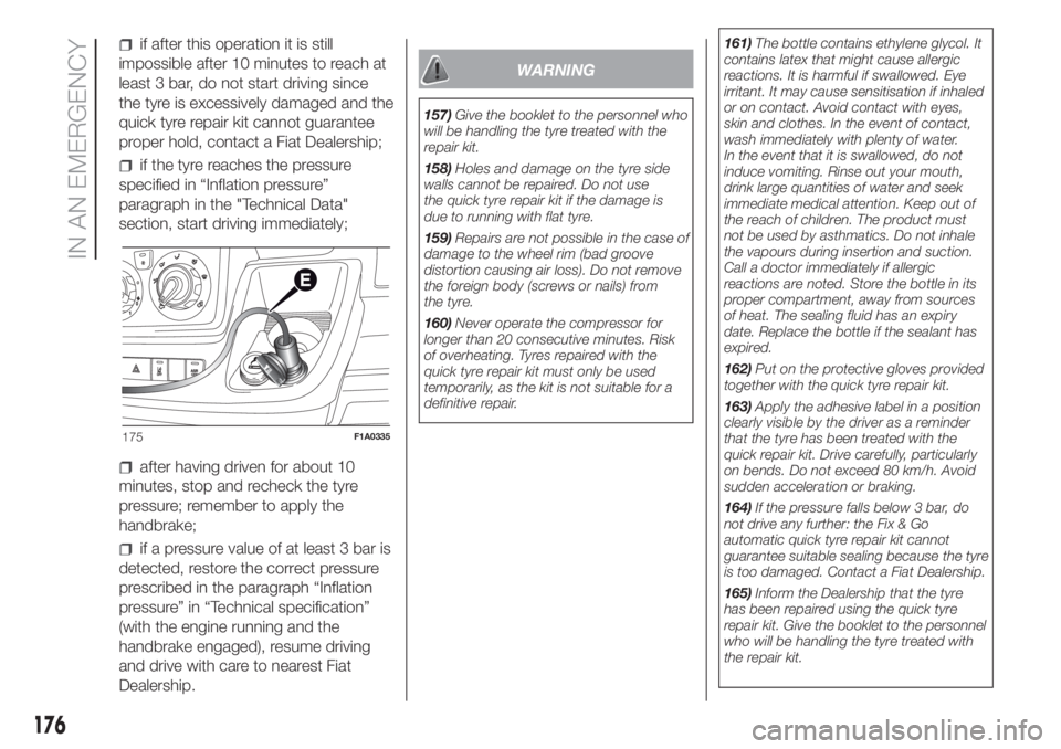
if after this operation it is still
impossible after 10 minutes to reach at
least 3 bar, do not start driving since
the tyre is excessively damaged and the
quick tyre repair kit cannot guarantee
proper hold, contact a Fiat Dealership;
if the tyre reaches the pressure
specified in “Inflation pressure”
paragraph in the "Technical Data"
section, start driving immediately;
after having driven for about 10
minutes, stop and recheck the tyre
pressure; remember to apply the
handbrake;
if a pressure value of at least 3 bar is
detected, restore the correct pressure
prescribed in the paragraph “Inflation
pressure” in “Technical specification”
(with the engine running and the
handbrake engaged), resume driving
and drive with care to nearest Fiat
Dealership.
WARNING
157)Give the booklet to the personnel who
will be handling the tyre treated with the
repair kit.
158)Holes and damage on the tyre side
walls cannot be repaired. Do not use
the quick tyre repair kit if the damage is
due to running with flat tyre.
159)Repairs are not possible in the case of
damage to the wheel rim (bad groove
distortion causing air loss). Do not remove
the foreign body (screws or nails) from
the tyre.
160)Never operate the compressor for
longer than 20 consecutive minutes. Risk
of overheating. Tyres repaired with the
quick tyre repair kit must only be used
temporarily, as the kit is not suitable for a
definitive repair.161)The bottle contains ethylene glycol. It
contains latex that might cause allergic
reactions. It is harmful if swallowed. Eye
irritant. It may cause sensitisation if inhaled
or on contact. Avoid contact with eyes,
skin and clothes. In the event of contact,
wash immediately with plenty of water.
In the event that it is swallowed, do not
induce vomiting. Rinse out your mouth,
drink large quantities of water and seek
immediate medical attention. Keep out of
the reach of children. The product must
not be used by asthmatics. Do not inhale
the vapours during insertion and suction.
Call a doctor immediately if allergic
reactions are noted. Store the bottle in its
proper compartment, away from sources
of heat. The sealing fluid has an expiry
date. Replace the bottle if the sealant has
expired.
162)Put on the protective gloves provided
together with the quick tyre repair kit.
163)Apply the adhesive label in a position
clearly visible by the driver as a reminder
that the tyre has been treated with the
quick repair kit. Drive carefully, particularly
on bends. Do not exceed 80 km/h. Avoid
sudden acceleration or braking.
164)If the pressure falls below 3 bar, do
not drive any further: the Fix & Go
automatic quick tyre repair kit cannot
guarantee suitable sealing because the tyre
is too damaged. Contact a Fiat Dealership.
165)Inform the Dealership that the tyre
has been repaired using the quick tyre
repair kit. Give the booklet to the personnel
who will be handling the tyre treated with
the repair kit.
175F1A0335
176
IN AN EMERGENCY