weight FIAT DUCATO BASE CAMPER 2017 Owner handbook (in English)
[x] Cancel search | Manufacturer: FIAT, Model Year: 2017, Model line: DUCATO BASE CAMPER, Model: FIAT DUCATO BASE CAMPER 2017Pages: 296, PDF Size: 14.44 MB
Page 106 of 296
CHILD RESTRAINT SYSTEMS RECOMMENDED BY FIAT PROFESSIONAL FOR
YOUR NEW DUCATO
Lineaccessori Fiat includes a complete range of child restraint systems to be fixed using the seat belt with three anchorage
points or the Isofix anchorages.
95) 96) 97) 98)
Weight group Child restraint systemType of child
restraint systemChild restraint system installation
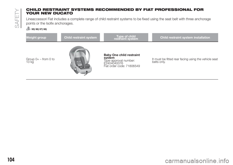
Group 0+ – from 0 to
13 kg
Baby One child restraint
system
Type-approval number:
E2404040076
Fiat order code: 71806549It must be fitted rear facing using the vehicle seat
belts only.
104
SAFETY
Page 107 of 296
Weight group Child restraint systemType of child
restraint systemChild restraint system installation
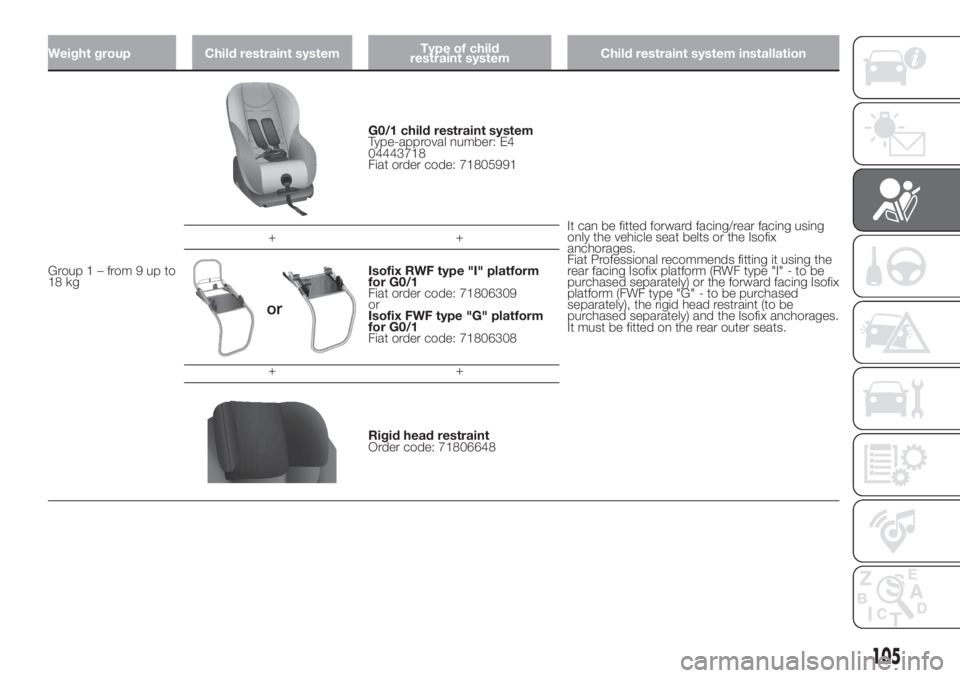
Group1–from9upto
18 kg
G0/1 child restraint system
Type-approval number: E4
04443718
Fiat order code: 71805991
It can be fitted forward facing/rear facing using
only the vehicle seat belts or the Isofix
anchorages.
Fiat Professional recommends fitting it using the
rear facing Isofix platform (RWF type "I" - to be
purchased separately) or the forward facing Isofix
platform (FWF type "G" - to be purchased
separately), the rigid head restraint (to be
purchased separately) and the Isofix anchorages.
It must be fitted on the rear outer seats. ++
Isofix RWF type "I" platform
for G0/1
Fiat order code: 71806309
or
Isofix FWF type "G" platform
for G0/1
Fiat order code: 71806308
++
Rigid head restraint
Order code: 71806648
105
Page 108 of 296
Weight group Child restraint systemType of child
restraint systemChild restraint system installation
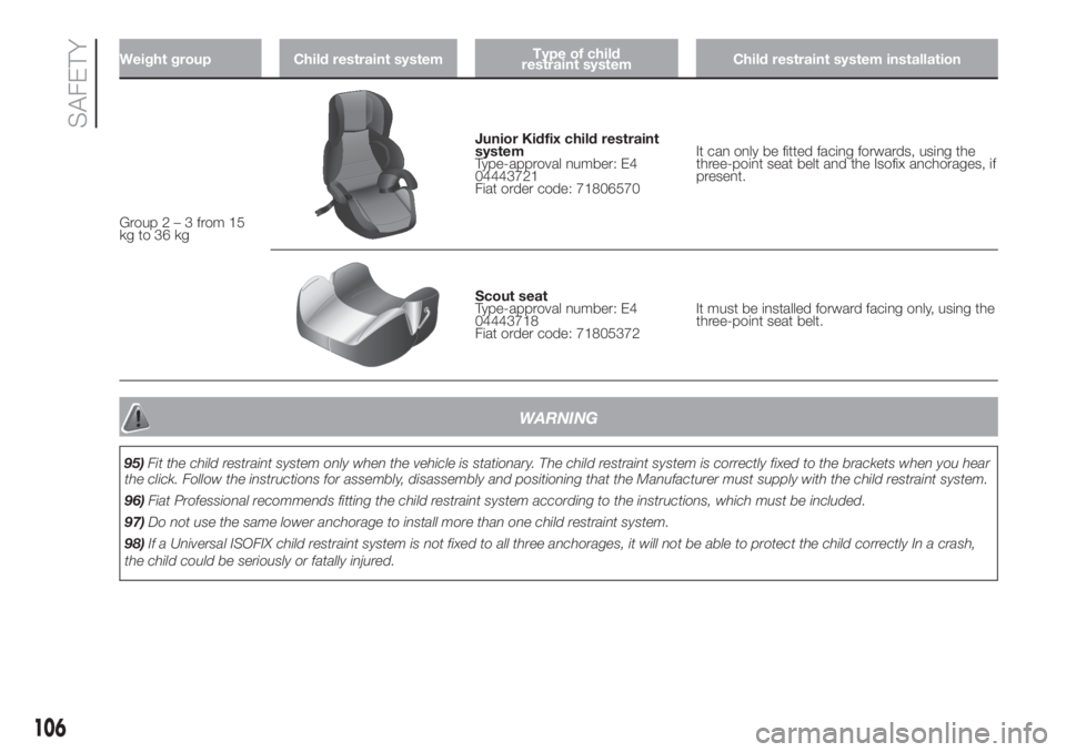
Group2–3from15
kg to 36 kg
Junior Kidfix child restraint
system
Type-approval number: E4
04443721
Fiat order code: 71806570It can only be fitted facing forwards, using the
three-point seat belt and the Isofix anchorages, if
present.
Scout seat
Type-approval number: E4
04443718
Fiat order code: 71805372It must be installed forward facing only, using the
three-point seat belt.
WARNING
95)Fit the child restraint system only when the vehicle is stationary. The child restraint system is correctly fixed to the brackets when you hear
the click. Follow the instructions for assembly, disassembly and positioning that the Manufacturer must supply with the child restraint system.
96)Fiat Professional recommends fitting the child restraint system according to the instructions, which must be included.
97)Do not use the same lower anchorage to install more than one child restraint system.
98)If a Universal ISOFIX child restraint system is not fixed to all three anchorages, it will not be able to protect the child correctly In a crash,
the child could be seriously or fatally injured.
106
SAFETY
Page 135 of 296
LOADING ADVICE
The Fiat Ducato version used by you
has been designed and type approved
on the basis of certain maximum
weights (see "Weights" table in the
"Technical Data" chapter): kerb weight,
payload, total weight, maximum weight
on front axle, maximum weight on
rear axle, towable weight.
IMPORTANT The maximum permitted
load on the floor fastenings is 500
kg; the maximum permitted load on the
side panel is 150 kg.
IMPORTANT For versions with right and
left side flaps, it is advisable to
reposition the release lever in the closed
position before lowering the sides.
133) 134) 135)
39)In addition to these general
precautions, some simple precautions
can improve driving safety, travelling
comfort and vehicle durability:
distribute the load evenly over the
platform: if it is necessary to
concentrate it in a single area, choose
an area mid-way between both axles;
lastly, remember that the vehicle’s
dynamic behaviour is affected by the
weight transported: in particular, the
stopping distances are longer,
especially at high speed.
WARNING
133)Bumpy roads and abrupt braking may
cause unexpected load shifting with
consequently hazardous situations for the
driver and passengers: before setting
off, secure the load tightly using the
partition and appropriate hooks, steel
cables, ropes or chains strong enough to
hold the items to be secured.
134)Even when the car is stopped on a
steep hill or side slope, opening the rear or
side doors could cause unsecured goods
to fall out.
135)If you wish to carry a reserve of petrol
in a can, observe the legal restrictions
and only use a can that is type-approved
and properly secured to the load
anchorage eyebolts. In the event of a
collision the fire risk is increased all the
same.
WARNING
39)Each of these must be strictly
observed and MUST NEVER BE
EXCEEDED in any case. In particular,
ensure that you never exceed the
maximum permitted weights on the front
and rear axles when arranging the load on
the vehicle (particularly if the vehicle is
equipped with a specific trim level).
133
Page 137 of 296
TOWING TRAILERS
IMPORTANT NOTES
The vehicle must be provided with a
type-approved tow hook and adequate
electrical system to tow caravans or
trailers. Installation should be carried
out by specialised personnel who
will issue the required papers for
travelling on roads.
Install any specific and/or additional
door mirrors as specified by the
Highway Code.
Remember that when towing a trailer,
steep hills are harder to climb, the
braking spaces increase and overtaking
takes longer depending on the overall
weight.
Engage a low gear when driving
downhill, rather than constantly using
the brake.
The weight of the trailer on the vehicle
tow hook will reduce the loading
capacity of the vehicle by the same
amount. Consider the weight of the
trailer fully laden, including accessories
and luggage, to make sure you do
not exceed the maximum towable
weight (shown on the vehicle
registration document).Do not exceed the speed limits specific
to each country you are driving in, in
the case of vehicles towing trailers.
In any case, the top speed must not
exceed 100 km/h.
You are advised to fit a suitable
stabiliser to the trailer drawbar.
In the vehicles equipped with parking
sensors, after fitting the tow hook
malfunctioning warnings may be
displayed, as some parts (tow bar, ball
tow hook) may be within the sensor
detection range. In this case the
detection range must be adjusted or
the parking assistance function must be
deactivated.
In vehicles equipped with "Comfort-
matic" transmission, make sure that the
gearbox is in neutral (N) (checking that
the vehicle moves when pushed) and
proceed in the same way as for towing
a normal vehicle with manual
transmission. If the gearbox cannot be
put in neutral, do not tow the vehicle
and contact a Fiat Dealership.
136) 137)
INSTALLING THE TOW
HOOK
The towing device should be fastened
to the body by specialised technicians
according to any additional and/or
integrative information supplied by the
Manufacturer of the device.
The towing device must meet current
regulations with reference to Directive
94/20/EC and subsequent
amendments.
For any version the towing device used
must match the towable weight of the
vehicle on which it is to be installed.
For the electric connection a standard
connector should be used which is
generally placed on a special bracket
normally fastened to the towing device,
and a special ECU for external trailer
light control must be installed on the
vehicle. For the electrical connection, 7
or 13 pin 12 V DC connections are to
be used (CUNA/UNI and ISO/DIN
Standards). Follow the instructions
provided by the vehicle manufacturer
and/or the tow hitch manufacturer.
Any electric brake (or electric winch,
etc.) should be supplied directly by the
battery through a cable with a section
of at least 2.5 mm
2.
IMPORTANT Electric brakes or other
devices must be used with engine
running.
135
Page 138 of 296
In addition to the electrical branches,
the vehicle's electric system can only
be connected to the supply cable for an
electric brake and to the cable for an
internal light, though not above 15
W. For connections use the preset
control unit with battery cable no less
than 2.5 mm
2.
IMPORTANT The trailer tow hook
contributes to the length of the vehicle.
When installing on long wheelbase
versions, it is only possible to install
removable tow hooks because the total
vehicle length limit of 6 metres is
exceeded.
If no trailer is fitted, the hook must be
removed from the attachment base and
it must not exceed the vehicle's
original length.
IMPORTANT If you wish to leave the
tow hook fitted without towing a trailer,
it is advisable to contact a Fiat
Dealership for the relevant system
update operations because the tow
hook could be detected as an obstacle
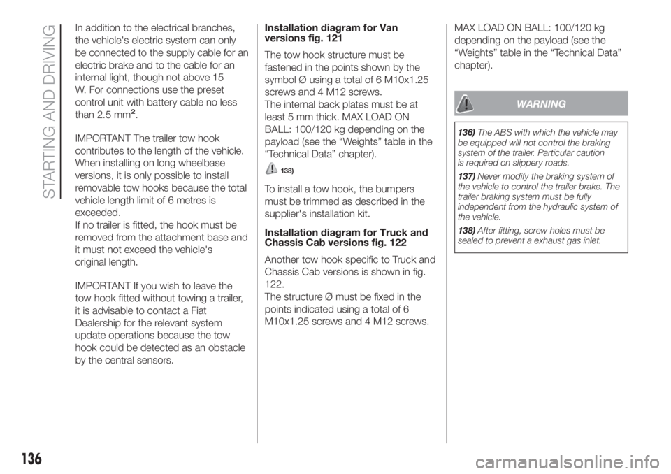
by the central sensors.Installation diagram for Van
versions fig. 121
The tow hook structure must be
fastened in the points shown by the
symbol Ø using a total of 6 M10x1.25
screws and 4 M12 screws.
The internal back plates must be at
least 5 mm thick. MAX LOAD ON
BALL: 100/120 kg depending on the
payload (see the “Weights” table in the
“Technical Data” chapter).
138)
To install a tow hook, the bumpers
must be trimmed as described in the
supplier's installation kit.
Installation diagram for Truck and
Chassis Cab versions fig. 122
Another tow hook specific to Truck and
Chassis Cab versions is shown in fig.
122.
The structure Ø must be fixed in the
points indicated using a total of 6
M10x1.25 screws and 4 M12 screws.MAX LOAD ON BALL: 100/120 kg
depending on the payload (see the
“Weights” table in the “Technical Data”
chapter).
WARNING
136)The ABS with which the vehicle may
be equipped will not control the braking
system of the trailer. Particular caution
is required on slippery roads.
137)Never modify the braking system of
the vehicle to control the trailer brake. The
trailer braking system must be fully
independent from the hydraulic system of
the vehicle.
138)After fitting, screw holes must be
sealed to prevent a exhaust gas inlet.
.
136
STARTING AND DRIVING
Page 172 of 296
CHANGING A WHEEL
GENERAL
INSTRUCTIONS
Wheel replacement and correct use of
the jack and spare wheel (for
versions/markets, where provided) call
for some precautions, which are listed
below.
145) 146) 147) 148) 149)
Please note that:
the jack weight is 4.5 kg;
the jack requires no adjustment;
the jack cannot be repaired: in the
event of a fault it must be replaced
by another original one;
no tool other than its cranking
device may be fitted on the jack.
150)
To change a wheel, proceed as
follows:
stop the vehicle in a position that is
not dangerous for oncoming traffic
where you can change the wheel safely.
The ground must be flat and sufficiently
compact;
switch off the engine and pull the
handbrake;
engage first gear or reverse;
put on the reflective safety jacket
(compulsory by law in certain countries)
before getting out of the vehicle;
indicate that the vehicle has broken
down using the devices required by
the law in the current country (e.g.
warning triangle, hazard lights, etc.);
In the event of a wheel change on a
slope or on unsurfaced roads, put
any object as stop under the wheels;
take the tool bag from under the
passenger seat (see "Compartment
under the front passenger side seat" in
the "Internal equipment" chapter in
"Knowing the vehicle").
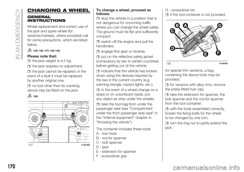
The container includes these tools:
A - tow hook
B - rod for spanner
C - bolt spanner
D - jack
E - extension for spanner
F - screwdriver gripG - screwdriver bit
if the tool container is not provided,
for special trim versions, a bag
containing the above tools may be
provided;
for versions with alloy rims, remove
the press-fitted hub cap;
take the extension for spanner, the
bolt spanner and the rod for spanner
from the tool container;
with the tools assembled correctly,
loosen the fixing bolts for the wheel
to be changed by one turn;
turn the ring nut to partly extend the
jack;
157F1A0168
158F1A0420
170
IN AN EMERGENCY
Page 210 of 296
TECHNICAL DATA
Everything you may find useful for
understanding how your vehicle
is made and works is contained in this
chapter and illustrated with data, tables
and graphics. For the enthusiasts and
the technician, but also just for those
who want to know every detail of their
vehicle.IDENTIFICATION DATA....................209
ENGINE CODES - BODYWORK
VERSION ........................................211
ENGINE ..........................................213
STEERING SYSTEM .......................216
WHEELS .........................................217
DIMENSIONS ..................................222
PERFORMANCE .............................232
WEIGHTS AND LOADS...................234
REFUELLING ..................................237
FLUIDS AND LUBRICANTS ............242
FUEL CONSUMPTION ....................245
CO2 EMISSIONS ...........................252
208
TECHNICAL DATA
Page 211 of 296
IDENTIFICATION
DATA
It is advisable to take note of the
identification codes. Identification codes
are printed and shown on the plates
as indicated below, together with the
positions:
VIN plate.
Chassis marking.
Bodywork paint identification plate.
Engine marking.
VEHICLE IDENTIFICATION
NUMBER (VIN) PLATE
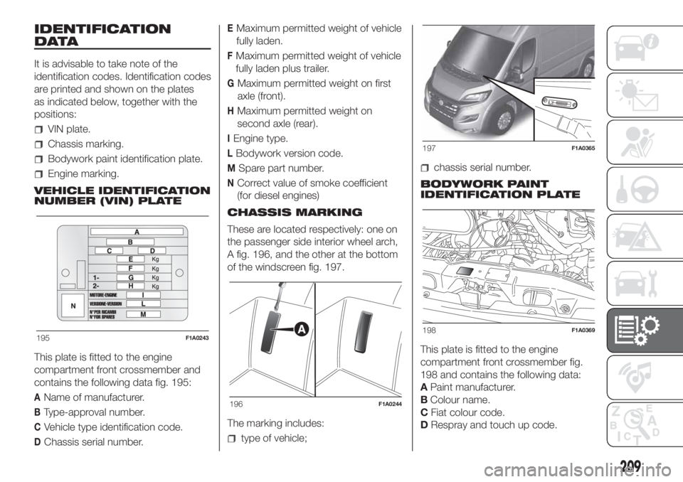
This plate is fitted to the engine
compartment front crossmember and
contains the following data fig. 195:
AName of manufacturer.
BType-approval number.
CVehicle type identification code.
DChassis serial number.
EMaximum permitted weight of vehicle
fully laden.
FMaximum permitted weight of vehicle
fully laden plus trailer.
GMaximum permitted weight on first
axle (front).
HMaximum permitted weight on
second axle (rear).
IEngine type.
LBodywork version code.
MSpare part number.
NCorrect value of smoke coefficient
(for diesel engines)
CHASSIS MARKING
These are located respectively: one on
the passenger side interior wheel arch,
A fig. 196, and the other at the bottom
of the windscreen fig. 197.
The marking includes:
type of vehicle;
chassis serial number.
BODYWORK PAINT
IDENTIFICATION PLATE
This plate is fitted to the engine
compartment front crossmember fig.
198 and contains the following data:
APaint manufacturer.
BColour name.
CFiat colour code.
DRespray and touch up code.
195F1A0243
196F1A0244
197F1A0365
198F1A0369
209
Page 223 of 296
COLD TYRE INFLATION PRESSURE (bar)
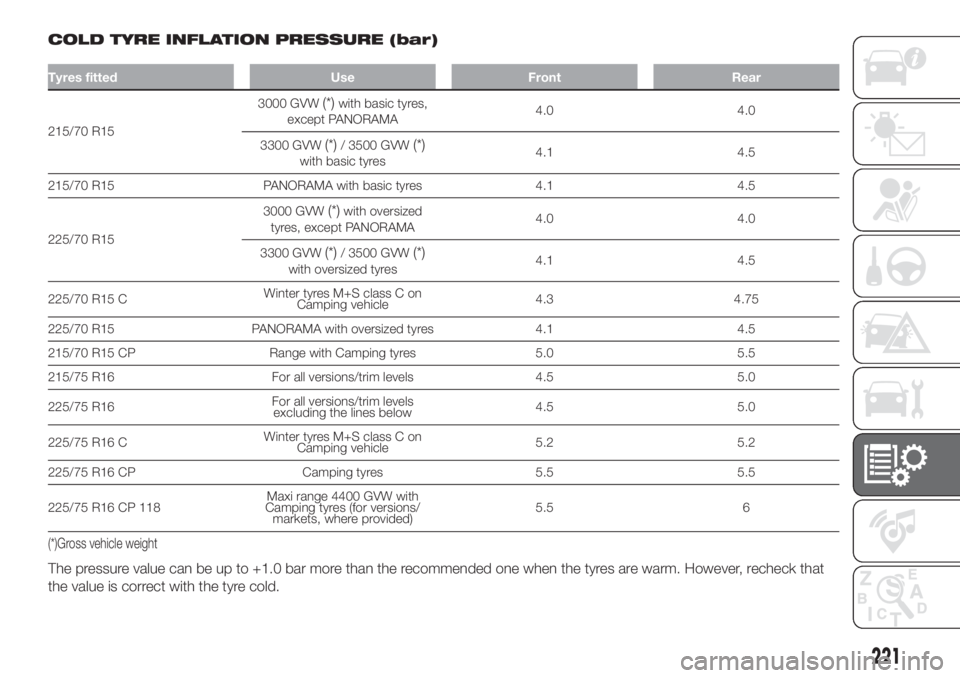
Tyres fitted Use Front Rear
215/70 R153000 GVW
(*)with basic tyres,
except PANORAMA4.0 4.0
3300 GVW
(*)/ 3500 GVW(*)with basic tyres4.1 4.5
215/70 R15 PANORAMA with basic tyres 4.1 4.5
225/70 R153000 GVW
(*)with oversized
tyres, except PANORAMA4.0 4.0
3300 GVW
(*)/ 3500 GVW(*)with oversized tyres4.1 4.5
225/70 R15 CWinter tyres M+S class C on
Camping vehicle4.3 4.75
225/70 R15 PANORAMA with oversized tyres 4.1 4.5
215/70 R15 CP Range with Camping tyres 5.0 5.5
215/75 R16 For all versions/trim levels 4.5 5.0
225/75 R16For all versions/trim levels
excluding the lines below4.5 5.0
225/75 R16 CWinter tyres M+S class C on
Camping vehicle5.2 5.2
225/75 R16 CP Camping tyres 5.5 5.5
225/75 R16 CP 118Maxi range 4400 GVW with
Camping tyres (for versions/
markets, where provided)5.5 6
(*)Gross vehicle weight
The pressure value can be up to +1.0 bar more than the recommended one when the tyres are warm. However, recheck that
the value is correct with the tyre cold.
221