display FIAT DUCATO BASE CAMPER 2017 Owner handbook (in English)
[x] Cancel search | Manufacturer: FIAT, Model Year: 2017, Model line: DUCATO BASE CAMPER, Model: FIAT DUCATO BASE CAMPER 2017Pages: 296, PDF Size: 14.44 MB
Page 118 of 296
16)If the engine fails to start with a gear
engaged, the potentially dangerous
situation due to the fact that the
transmission is automatically placed in
neutral will be signalled by a buzzer.
17)If the warning light
flashes for 60
seconds after starting or during an
extended towing period, this indicates a
problem in the glow plug preheating
system. Use the vehicle normally if the
engine starts, but contact a Fiat Dealership
as soon as possible.
18)Remember that the brake servo and
power steering are not operational until the
engine has been started, so you need to
apply much more force than usual to
the brake pedal and steering wheel.
19)Never bump start the engine by
pushing, towing or coasting downhill. This
could cause fuel to flow into the catalytic
converter and damage it beyond repair.
20)A quick burst on the accelerator before
stopping the engine serves no practical
purpose; it wastes fuel and is especially
damaging to turbocharged engines.
21)In some cases, when the engine
switches off, the fan could activate for max.
120 seconds.
WHEN PARKED
116)
22)
Proceed as follows when parking and
leaving the vehicle:
engage the gear (on a slope, engage
first gear if the vehicle is facing uphill
or reverse if it is facing downhill) and
leave the wheels steered;
stop the engine and engage the
handbrake;
always remove the ignition key.
If the vehicle is parked on a steep
slope, it is advisable to block the
wheels with a wedge or stone.
On versions equipped with automatic
transmission (Comfort matic), wait
for the letterPto appear on the display
before releasing the brake pedal.
IMPORTANTNEVERleave the vehicle
with the gearbox in neutral (or, on
versions equipped with automatic
(Comfort matic) transmission, before
putting the shift lever in thePposition).HANDBRAKE
Handbrake engagement:The
handbrake lever is located to the left of
the driver's seat. Pull the lever upwards
to engage the handbrake and ensure
that the vehicle does not move.
Handbrake disengagement:slightly
raise the lever, hold the button A
pressed and check that the
warning light switches off on the
instrument panel.
Press the brake pedal when carrying
out this operation to prevent the vehicle
from moving accidentally.
WARNING
116)Never leave children unattended in
the vehicle. Always remove the ignition key
when leaving the vehicle and take it out
with you.
WARNING
22)If the vehicle is equipped with
self-levelling air suspension, always check
that there is sufficient space above the roof
and around the vehicle when parking.
Indeed, the vehicle could raise (or lower)
automatically depending on load or
temperature changes.
116
STARTING AND DRIVING
Page 120 of 296
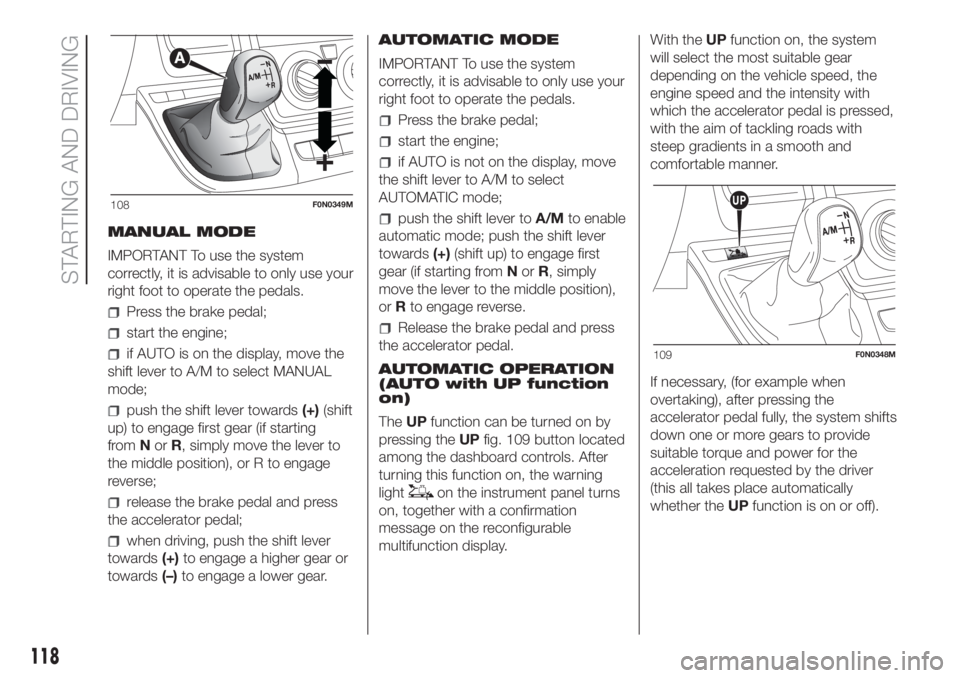
MANUAL MODE
IMPORTANT To use the system
correctly, it is advisable to only use your
right foot to operate the pedals.
Press the brake pedal;
start the engine;
if AUTO is on the display, move the
shift lever to A/M to select MANUAL
mode;
push the shift lever towards(+)(shift
up) to engage first gear (if starting
fromNorR, simply move the lever to
the middle position), or R to engage
reverse;
release the brake pedal and press
the accelerator pedal;
when driving, push the shift lever
towards(+)to engage a higher gear or
towards(–)to engage a lower gear.AUTOMATIC MODE
IMPORTANT To use the system
correctly, it is advisable to only use your
right foot to operate the pedals.
Press the brake pedal;
start the engine;
if AUTO is not on the display, move
the shift lever to A/M to select
AUTOMATIC mode;
push the shift lever toA/Mto enable
automatic mode; push the shift lever
towards(+)(shift up) to engage first
gear (if starting fromNorR, simply
move the lever to the middle position),
orRto engage reverse.
Release the brake pedal and press
the accelerator pedal.
AUTOMATIC OPERATION
(AUTO with UP function
on)
TheUPfunction can be turned on by
pressing theUPfig. 109 button located
among the dashboard controls. After
turning this function on, the warning
light
on the instrument panel turns
on, together with a confirmation
message on the reconfigurable
multifunction display.With theUPfunction on, the system
will select the most suitable gear
depending on the vehicle speed, the
engine speed and the intensity with
which the accelerator pedal is pressed,
with the aim of tackling roads with
steep gradients in a smooth and
comfortable manner.
If necessary, (for example when
overtaking), after pressing the
accelerator pedal fully, the system shifts
down one or more gears to provide
suitable torque and power for the
acceleration requested by the driver
(this all takes place automatically
whether theUPfunction is on or off).
108F0N0349M
109F0N0348M
118
STARTING AND DRIVING
Page 123 of 296
When the device is active, the vehicle
speed depends on the accelerator
pedal, until the programmed speed limit
is reached (see "Speed limit
programming" paragraph).
If necessary (in the event of overtaking
for example), the set speed limit can
be exceeded by fully depressing the
accelerator pedal.
By gradually reducing the pressure on
the accelerator pedal, the function
will be reactivated as soon as the
vehicle speed drops below the
programmed speed.
Turning the device on
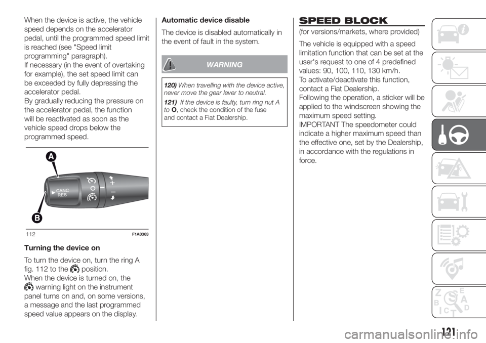
To turn the device on, turn the ring A
fig. 112 to the
position.
When the device is turned on, the
warning light on the instrument
panel turns on and, on some versions,
a message and the last programmed
speed value appears on the display.Automatic device disable
The device is disabled automatically in
the event of fault in the system.
WARNING
120)When travelling with the device active,
never move the gear lever to neutral.
121)If the device is faulty, turn ring nut A
toO, check the condition of the fuse
and contact a Fiat Dealership.
SPEED BLOCK
(for versions/markets, where provided)
The vehicle is equipped with a speed
limitation function that can be set at the
user's request to one of 4 predefined
values: 90, 100, 110, 130 km/h.
To activate/deactivate this function,
contact a Fiat Dealership.
Following the operation, a sticker will be
applied to the windscreen showing the
maximum speed setting.
IMPORTANT The speedometer could
indicate a higher maximum speed than
the effective one, set by the Dealership,
in accordance with the regulations in
force.
112F1A0363
121
Page 124 of 296
PARKING SENSORS
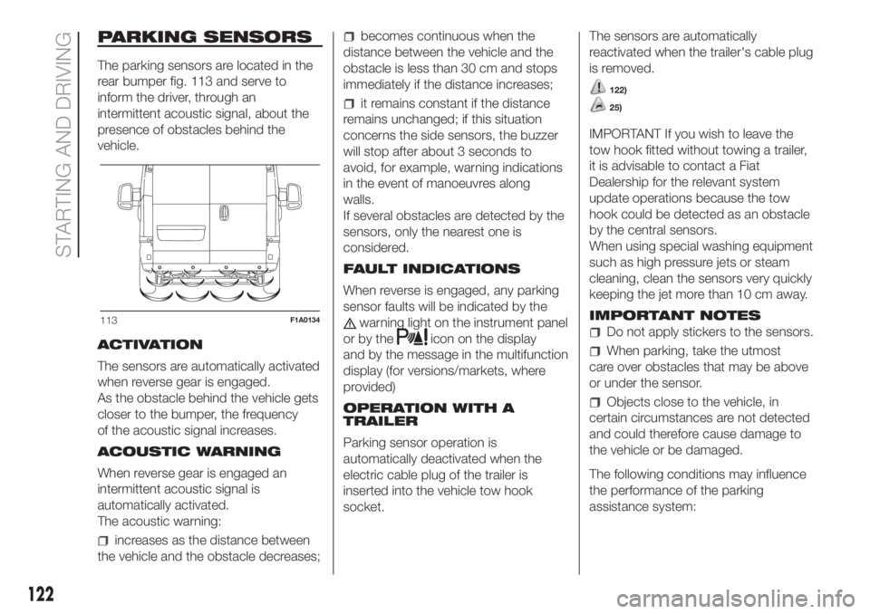
The parking sensors are located in the
rear bumper fig. 113 and serve to
inform the driver, through an
intermittent acoustic signal, about the
presence of obstacles behind the
vehicle.
ACTIVATION
The sensors are automatically activated
when reverse gear is engaged.
As the obstacle behind the vehicle gets
closer to the bumper, the frequency
of the acoustic signal increases.
ACOUSTIC WARNING
When reverse gear is engaged an
intermittent acoustic signal is
automatically activated.
The acoustic warning:
increases as the distance between
the vehicle and the obstacle decreases;
becomes continuous when the
distance between the vehicle and the
obstacle is less than 30 cm and stops
immediately if the distance increases;
it remains constant if the distance
remains unchanged; if this situation
concerns the side sensors, the buzzer
will stop after about 3 seconds to
avoid, for example, warning indications
in the event of manoeuvres along
walls.
If several obstacles are detected by the
sensors, only the nearest one is
considered.
FAULT INDICATIONS
When reverse is engaged, any parking
sensor faults will be indicated by the
warning light on the instrument panel
or by the
icon on the display
and by the message in the multifunction
display (for versions/markets, where
provided)
OPERATION WITH A
TRAILER
Parking sensor operation is
automatically deactivated when the
electric cable plug of the trailer is
inserted into the vehicle tow hook
socket.The sensors are automatically
reactivated when the trailer's cable plug
is removed.
122)
25)
IMPORTANT If you wish to leave the
tow hook fitted without towing a trailer,
it is advisable to contact a Fiat
Dealership for the relevant system
update operations because the tow
hook could be detected as an obstacle
by the central sensors.
When using special washing equipment
such as high pressure jets or steam
cleaning, clean the sensors very quickly
keeping the jet more than 10 cm away.
IMPORTANT NOTES
Do not apply stickers to the sensors.
When parking, take the utmost
care over obstacles that may be above
or under the sensor.
Objects close to the vehicle, in
certain circumstances are not detected
and could therefore cause damage to
the vehicle or be damaged.
The following conditions may influence
the performance of the parking
assistance system:
113F1A0134
122
STARTING AND DRIVING
Page 125 of 296
Reduced sensor sensitivity and a
reduction in the parking assistance
system performance could be due to
the presence on the surface of the
sensor of: ice, snow, mud, thick paint.
The sensor may detect a non-
existent obstacle (echo noise) due to
mechanical noises, for example when
washing the vehicle, in case of rain,
strong wind, hail.
The warnings sent by the sensor
can also be altered by the presence of
ultrasonic systems (e.g. pneumatic
brakes of trucks or pneumatic drills)
near the car.
The performance of the parking
assistance system may also be affected
by the position of the sensors. For
example by a change in the ride setting
(caused by the wear of the shock
absorbers, suspension), changing the
tyres, overloading the vehicle and
carrying out specific tuning operations
that require the vehicle to be lowered.
Detection of obstacles in the upper
part of the vehicle (particularly in the
case of vans or chassis cabs) may not
be guaranteed because the system
detects obstacles that could strike the
lower part of the vehicle.
WARNING
122)The driver is always responsible for
parking and other dangerous manoeuvres.
While carrying out these manoeuvres,
always make sure that no people
(especially children) or animals are in the
area concerned. The parking sensors
are used to assist the driver, who must
never allow his attention to lapse during
potentially dangerous manoeuvres, even
those executed at low speeds.
WARNING
25)For correct operation of the system,
sensors must always be clean from mud,
dirt, snow or ice. Be careful not to scratch
or damage the sensors while cleaning
them. Avoid using dry, rough or hard
cloths. The sensors must be washed using
clean water, with the addition of vehicle
shampoo if necessary.
REAR CAMERA
(PARKVIEW® REAR
BACK UP CAMERA)
(for versions/markets, where provided)
123)
26)
The vehicle may be equipped with a
ParkView® Rear Back Up Camera,
which allows the driver to see the
surrounding area behind the vehicle on
the display when reverse is engaged
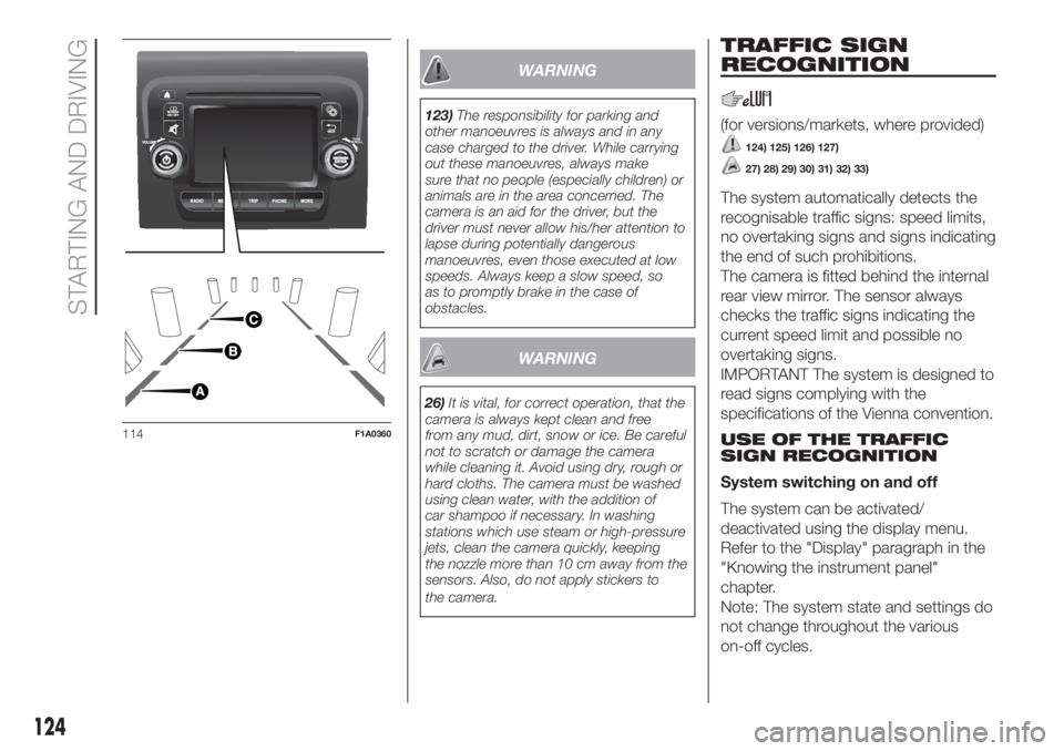
or the tailgate is opened fig. 114.
SYMBOLS AND
MESSAGES ON THE
DISPLAY
When displayed, the static line grid
shows the width of the vehicle.
The grid shows separate areas,
allowing you to see the distance from
the rear of the vehicle.
The table below shows the
approximate distances for each area:
Area (reference
fig. 114)Distance from the
rear of the vehicle
Red (A) 0–30 cm
Yellow (B) 30–100 cm
Green (C) 1 m or more
123
Page 126 of 296
WARNING
123)The responsibility for parking and
other manoeuvres is always and in any
case charged to the driver. While carrying
out these manoeuvres, always make
sure that no people (especially children) or
animals are in the area concerned. The
camera is an aid for the driver, but the
driver must never allow his/her attention to
lapse during potentially dangerous
manoeuvres, even those executed at low
speeds. Always keep a slow speed, so
as to promptly brake in the case of
obstacles.
WARNING
26)It is vital, for correct operation, that the
camera is always kept clean and free
from any mud, dirt, snow or ice. Be careful
not to scratch or damage the camera
while cleaning it. Avoid using dry, rough or
hard cloths. The camera must be washed
using clean water, with the addition of
car shampoo if necessary. In washing
stations which use steam or high-pressure
jets, clean the camera quickly, keeping
the nozzle more than 10 cm away from the
sensors. Also, do not apply stickers to
the camera.
TRAFFIC SIGN
RECOGNITION
(for versions/markets, where provided)
124) 125) 126) 127)
27) 28) 29) 30) 31) 32) 33)
The system automatically detects the
recognisable traffic signs: speed limits,
no overtaking signs and signs indicating
the end of such prohibitions.
The camera is fitted behind the internal
rear view mirror. The sensor always
checks the traffic signs indicating the
current speed limit and possible no
overtaking signs.
IMPORTANT The system is designed to
read signs complying with the
specifications of the Vienna convention.
USE OF THE TRAFFIC
SIGN RECOGNITION
System switching on and off
The system can be activated/
deactivated using the display menu.
Refer to the "Display" paragraph in the
"Knowing the instrument panel"
chapter.
Note: The system state and settings do
not change throughout the various
on-off cycles.
114F1A0360
124
STARTING AND DRIVING
Page 133 of 296
These two systems ensure compliance
with the diesel emissions requirements;
at the same it maintains fuel saving
levels, driveability, torque and power.
For the system messages and warnings
refer to the "Warning lights and
messages" paragraph in the "Knowing
the instrument panel" section.
Notes
When you stop the vehicle you
could hear a distinct click coming from
under the vehicle due to the UREA
injection system, this is normal.
The UREA injection system pump
continues to operate for a short period
of time after the engine is switched
off, to purge the circuit. This is normal,
and you can still hear its noise from
under the vehicle.
VERSION WITH
METHANE SYSTEM
(Natural Power)
37) 38)
INTRODUCTION
The "Natural Power" version of the Fiat
Ducato features two fuel system, one
primary natural gas (methane) system
and one emergency petrol system.
METHANE CYLINDERS
The vehicle is equipped with five
cylinders (total capacity of about 218
litres) located under the vehicle floor
and protected by two special shields.
The cylinders are the tank that contains
the methane in its compressed
gaseous state (nominal pressure of 200
bar at 15°C). The methane, stored in
the cylinders at high pressure, flows
through a dedicated pipe to reach the
pressure regulator/reduction unit which
supplies the 4 methane injectors at
low pressure (about 6 bar).
IMPORTANT If gas is smelled, switch
from methane operation to petrol
operation and immediately go to a Fiat
Dealership to have the vehicle checked
and possible system faults excluded.FUEL SWITCHING
LOGICS
Management of switching between the
two different fuel supplies is fully
automatic, and carried out by the
engine control unit.
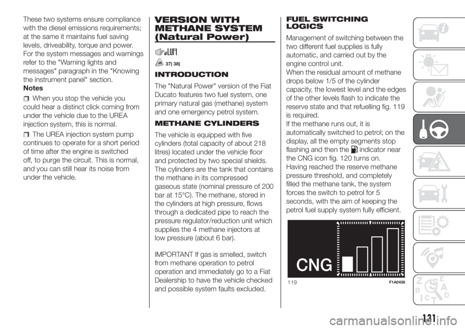
When the residual amount of methane
drops below 1/5 of the cylinder
capacity, the lowest level and the edges
of the other levels flash to indicate the
reserve state and that refuelling fig. 119
is required.
If the methane runs out, it is
automatically switched to petrol; on the
display, all the empty segments stop
flashing and then the
indicator near
the CNG icon fig. 120 turns on.
Having reached the reserve methane
pressure threshold, and completely
filled the methane tank, the system
forces the switch to petrol for 5
seconds, with the aim of keeping the
petrol fuel supply system fully efficient.
119F1A0436
131
Page 137 of 296
TOWING TRAILERS
IMPORTANT NOTES
The vehicle must be provided with a
type-approved tow hook and adequate
electrical system to tow caravans or
trailers. Installation should be carried
out by specialised personnel who
will issue the required papers for
travelling on roads.
Install any specific and/or additional
door mirrors as specified by the
Highway Code.
Remember that when towing a trailer,
steep hills are harder to climb, the
braking spaces increase and overtaking
takes longer depending on the overall
weight.
Engage a low gear when driving
downhill, rather than constantly using
the brake.
The weight of the trailer on the vehicle
tow hook will reduce the loading
capacity of the vehicle by the same
amount. Consider the weight of the
trailer fully laden, including accessories
and luggage, to make sure you do
not exceed the maximum towable
weight (shown on the vehicle
registration document).Do not exceed the speed limits specific
to each country you are driving in, in
the case of vehicles towing trailers.
In any case, the top speed must not
exceed 100 km/h.
You are advised to fit a suitable
stabiliser to the trailer drawbar.
In the vehicles equipped with parking
sensors, after fitting the tow hook
malfunctioning warnings may be
displayed, as some parts (tow bar, ball
tow hook) may be within the sensor
detection range. In this case the
detection range must be adjusted or
the parking assistance function must be
deactivated.
In vehicles equipped with "Comfort-
matic" transmission, make sure that the
gearbox is in neutral (N) (checking that
the vehicle moves when pushed) and
proceed in the same way as for towing
a normal vehicle with manual
transmission. If the gearbox cannot be
put in neutral, do not tow the vehicle
and contact a Fiat Dealership.
136) 137)
INSTALLING THE TOW
HOOK
The towing device should be fastened
to the body by specialised technicians
according to any additional and/or
integrative information supplied by the
Manufacturer of the device.
The towing device must meet current
regulations with reference to Directive
94/20/EC and subsequent
amendments.
For any version the towing device used
must match the towable weight of the
vehicle on which it is to be installed.
For the electric connection a standard
connector should be used which is
generally placed on a special bracket
normally fastened to the towing device,
and a special ECU for external trailer
light control must be installed on the
vehicle. For the electrical connection, 7
or 13 pin 12 V DC connections are to
be used (CUNA/UNI and ISO/DIN
Standards). Follow the instructions
provided by the vehicle manufacturer
and/or the tow hitch manufacturer.
Any electric brake (or electric winch,
etc.) should be supplied directly by the
battery through a cable with a section
of at least 2.5 mm
2.
IMPORTANT Electric brakes or other
devices must be used with engine
running.
135
Page 170 of 296
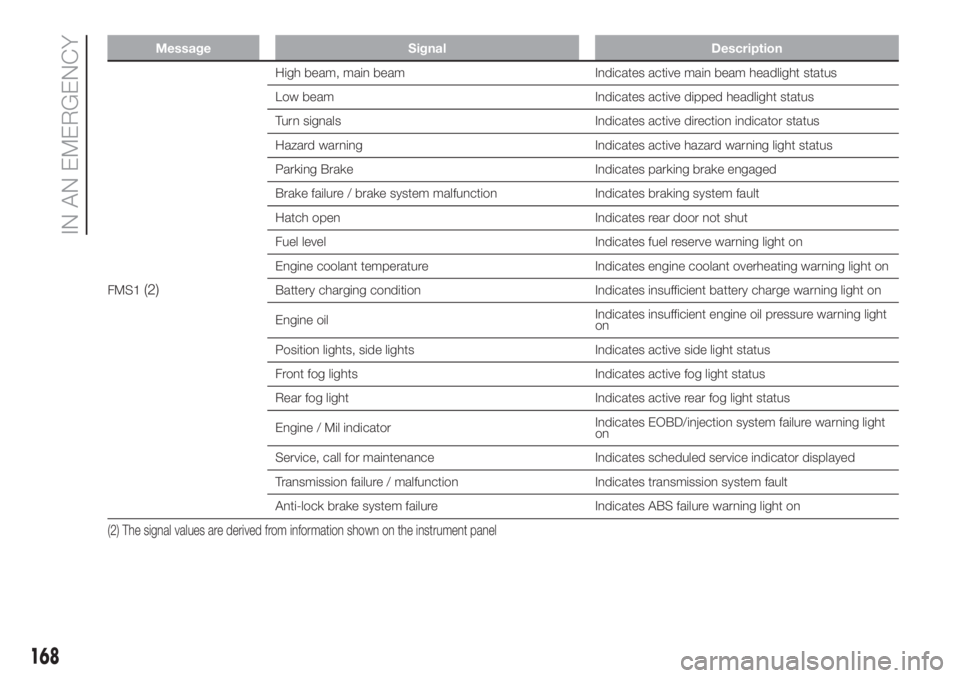
Message Signal Description
FMS1(2)
High beam, main beam Indicates active main beam headlight status
Low beam Indicates active dipped headlight status
Turn signals Indicates active direction indicator status
Hazard warning Indicates active hazard warning light status
Parking Brake Indicates parking brake engaged
Brake failure / brake system malfunction Indicates braking system fault
Hatch open Indicates rear door not shut
Fuel level Indicates fuel reserve warning light on
Engine coolant temperature Indicates engine coolant overheating warning light on
Battery charging condition Indicates insufficient battery charge warning light on
Engine oilIndicates insufficient engine oil pressure warning light
on
Position lights, side lights Indicates active side light status
Front fog lights Indicates active fog light status
Rear fog light Indicates active rear fog light status
Engine / Mil indicatorIndicates EOBD/injection system failure warning light
on
Service, call for maintenance Indicates scheduled service indicator displayed
Transmission failure / malfunction Indicates transmission system fault
Anti-lock brake system failure Indicates ABS failure warning light on
(2) The signal values are derived from information shown on the instrument panel
168
IN AN EMERGENCY
Page 171 of 296
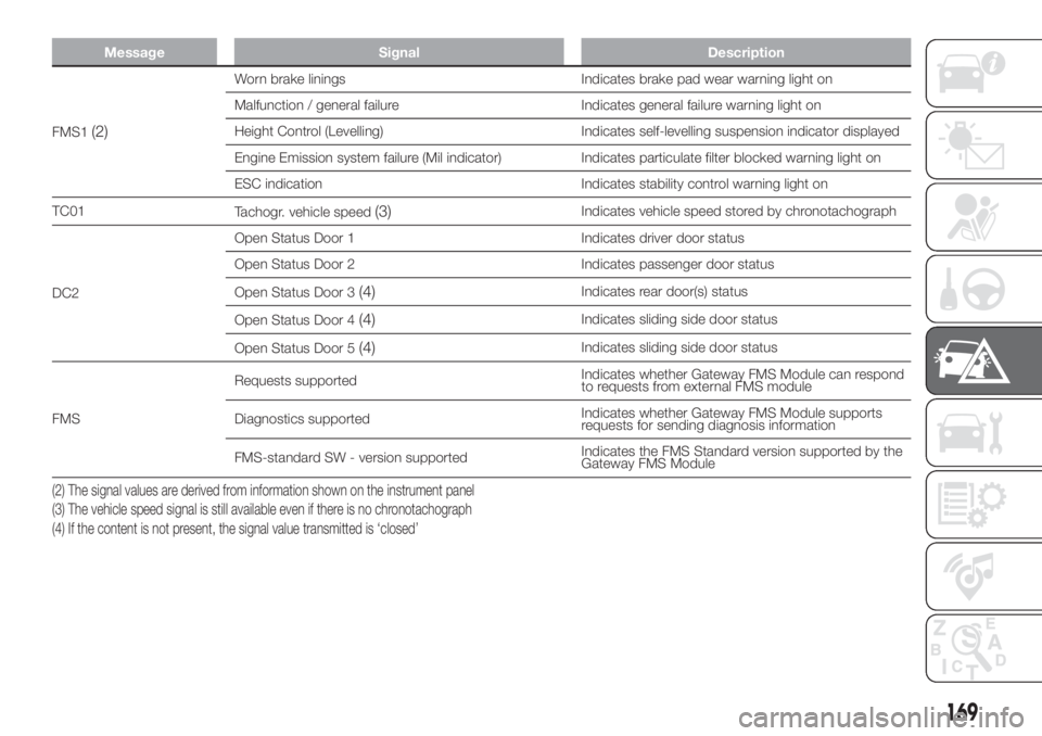
Message Signal Description
FMS1(2)
Worn brake linings Indicates brake pad wear warning light on
Malfunction / general failure Indicates general failure warning light on
Height Control (Levelling) Indicates self-levelling suspension indicator displayed
Engine Emission system failure (Mil indicator) Indicates particulate filter blocked warning light on
ESC indication Indicates stability control warning light on
TC01
Tachogr. vehicle speed
(3)Indicates vehicle speed stored by chronotachograph
DC2Open Status Door 1 Indicates driver door status
Open Status Door 2 Indicates passenger door status
Open Status Door 3
(4)Indicates rear door(s) status
Open Status Door 4
(4)Indicates sliding side door status
Open Status Door 5
(4)Indicates sliding side door status
FMSRequests supportedIndicates whether Gateway FMS Module can respond
to requests from external FMS module
Diagnostics supportedIndicates whether Gateway FMS Module supports
requests for sending diagnosis information
FMS-standard SW - version supportedIndicates the FMS Standard version supported by the
Gateway FMS Module
(2) The signal values are derived from information shown on the instrument panel
(3) The vehicle speed signal is still available even if there is no chronotachograph
(4) If the content is not present, the signal value transmitted is ‘closed’
169