fuse index FIAT FIORINO 2012 Owner handbook (in English)
[x] Cancel search | Manufacturer: FIAT, Model Year: 2012, Model line: FIORINO, Model: FIAT FIORINO 2012Pages: 210, PDF Size: 4.9 MB
Page 12 of 210
11
SAFETY
STARTING
AND DRIVING
WARNING
LIGHTS AND
MESSAGES
IN AN
EMERGENCY
MAINTENANCE
AND CARE
TECHNICAL
SPECIFICATIONS
INDEX
DASHBOARD
AND CONTROLS
ALARM
(for versions/markets, where provided)
In addition to all the remote control func-
tions described above, an alarm has been
installed, which is controlled by a receiv-
er unit located under the dashboard near
the fuse box.
ALARM TRIPPING
The alarm trips in the following cases:
❒when one of the doors or bonnet is
opened illegitimately (perimeter pro-
tection);
❒when the ignition system is started up
(ignition key rotated to MAR);
❒when the battery cables are cut;
❒when someone is moving inside the
passenger compartment (volumetric
protection);
❒when the vehicle is unusually lift-
ed/tilted.
Depending on the markets where the ve-
hicle is sold, alarm tripping causes either
a siren or direction indicators to go on
(for approx. 26 seconds). Alarm tripping
and the number of cycles depend on the
sales market.Provision has been made for a maximum
number of acoustic/visual cycles, after
which the system resumes its standard
control function.
Volumetric and anti-lift protections are
disabled by pressing the control button in-
stalled on the front dashboard (see para-
graph “Anti-lift protections).
IMPORTANT The engine stop function is
guaranteed by the Fiat CODE, which is au-
tomatically activated when the ignition key
is extracted from the starter device.
ENABLING THE ALARM
Keep the doors and bonnets closed and
either turn the ignition key to STOPor
remove it. Direct the key with the remote
control towards the vehicle and press but-
ton
Á, then release it.
Excluding some versions for specific mar-
kets, the system produces a sound warn-
ing (beep) and enables door locking.
Before the alarm is enabled, a self-test is
run. If a failure is detected, the system pro-
duces a new acoustic signal and shows a
message on the display (see section
“Warning lights and messages”). If this is the case, disable the alarm by
pressing button Æ, check correct locking
of the doors, bonnet and boot, and enable
the alarm again by pressing button
Á.
If a door or the bonnet is not correctly
closed, it will be excluded from the test-
ing by the alarm system.
If the alarm produces an acoustic signal
even when the doors, bonnet and boot
are correctly closed, a failure has occurred
in system operation. Go to a Fiat Dealer-
ship.
IMPORTANT If the central door locking
system is engaged using the metal insert
of the key, the alarm is not enabled.
IMPORTANT Originally, the alarm is con-
figured in compliance with the regulations
existing in the different countries.
001-035 Fiorino GB 1ed:001-035 Fiorino GB 1ed 2-12-2009 16:14 Pagina 11
Page 121 of 210
120
SAFETY
IN AN
EMERGENCY
MAINTENANCE
AND CARE
TECHNICAL
SPECIFICATIONS
INDEX
DASHBOARDAND CONTROLS
STARTING
AND DRIVING
WARNING
LIGHTS AND
MESSAGES
GENERIC FAILURE
INDICATION
(amber)
The warning light turns on in the follow-
ing circumstances.
Engine oil pressure sensor failure
The warning light turns on when a failure
is detected by the engine oil pressure sen-
sor.
Go to a Fiat Dealership to have the fault
fixed as soon as possible.
External light failure
(for versions/markets, where provided)
See description of warning light 6.
Fuel cut-off switch tripped
The warning light comes on when the in-
ertial fuel cut-off switch is triggered.
The display will show the dedicated mes-
sage.
Parking sensor failure
(for versions/markets, where provided)
See description of warning light t.BRAKE PAD WEAR
(amber)
The warning light on the dial
turns on if the front brake pads are worn;
in this case have them changed as soon
as possible.
On certain versions the dedicated mes-
sage is displayed.
èd
EXTERNAL LIGHTS
FAILURE
(amber)
The warning light comes on (on some ver-
sions only) when a failure is detected in
one of the following lights:
– side/taillights
– stop lights
– rear fog lights
– direction indicators
– plate lights.
The fault identified in the lights above may
be due to: one or more burnt lamps, a
blown protection fuse or interruption of
the electrical connection.
On certain versions warning light èturns
on as an alternative.
On certain versions the dedicated mes-
sage is displayed.
W
111-122 Fiorino GB 1ed:111-122 Fiorino GB 1ed 2-12-2009 16:18 Pagina 120
Page 124 of 210
123
SAFETY
MAINTENANCE
AND CARE
TECHNICAL
SPECIFICATIONS
INDEX
DASHBOARDAND CONTROLS
STARTING
AND DRIVING
WARNING
LIGHTS AND
MESSAGES
IN AN
EMERGENCY
STARTING THE ENGINE ................................................. 124
IF A TYRE IS PUNCTURED............................................... 125
QUICK TYRE REPAIR KIT
AUTOMATIC FIX & GO ................................................... 130
WHEN NEEDING TO CHANGE A BULB ................... 134
IF AN EXTERIOR LIGHT BURNS OUT.......................... 137
IF AN INTERIOR LIGHT BURNS OUT ......................... 142
IF A FUSE BLOWS ............................................................... 145
IF THE BATTERY IS FLAT ................................................. 153
IF THE VEHICLE NEEDS TO BE LIFTED ....................... 153
IF THE VEHICLE NEEDS TO BE TOWED .................... 154
I I
N N
A A
N N
E E
M M
E E
R R
G G
E E
N N
C C
Y Y
In an emergency we recommend that you call the toll-free number found on the
Warranty Booklet. You can also connect to the site www.fiat.com
to search for the nearest Fiat Dealership point
123-154 Fiorino GB 1ed:123-154 Fiorino GB 1ed 3-12-2009 15:33 Pagina 123
Page 128 of 210
127
SAFETY
MAINTENANCE
AND CARE
TECHNICAL
SPECIFICATIONS
INDEX
DASHBOARDAND CONTROLS
STARTING
AND DRIVING
WARNING
LIGHTS AND
MESSAGES
IN AN
EMERGENCY
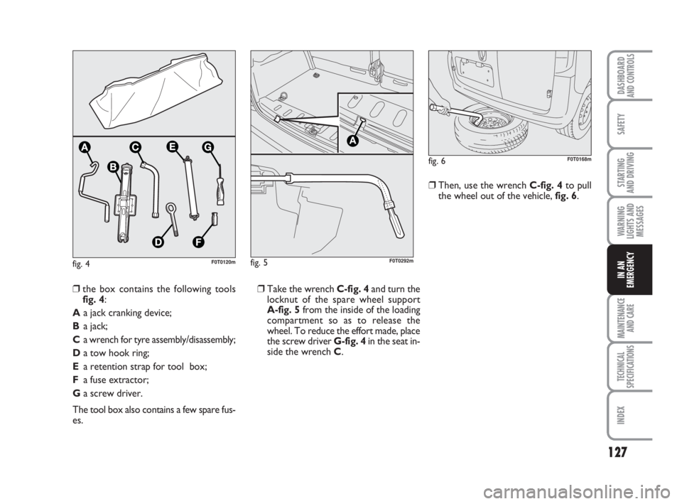
fig. 4F0T0120m
❒Take the wrench C-fig. 4and turn the
locknut of the spare wheel support
A-fig. 5from the inside of the loading
compartment so as to release the
wheel. To reduce the effort made, place
the screw driver G-fig. 4in the seat in-
side the wrench C.❒Then, use the wrench C-fig. 4to pull
the wheel out of the vehicle, fig. 6.
❒the box contains the following tools
fig. 4:
Aa jack cranking device;
Ba jack;
Ca wrench for tyre assembly/disassembly;
Da tow hook ring;
Ea retention strap for tool box;
Fa fuse extractor;
Ga screw driver.
The tool box also contains a few spare fus-
es.
fig. 6F0T0168m
fig. 5
A
F0T0292m
123-154 Fiorino GB 1ed:123-154 Fiorino GB 1ed 3-12-2009 15:33 Pagina 127
Page 131 of 210
130
SAFETY
MAINTENANCE
AND CARE
TECHNICAL
SPECIFICATIONS
INDEX
DASHBOARDAND CONTROLS
STARTING
AND DRIVING
WARNING
LIGHTS AND
MESSAGES
IN AN
EMERGENCY
QUICK TYRE REPAIR
KIT FIX & GO automatic
The automatic fast tyre repair kit Fix & Go
automatic is placed in a container in the
boot.
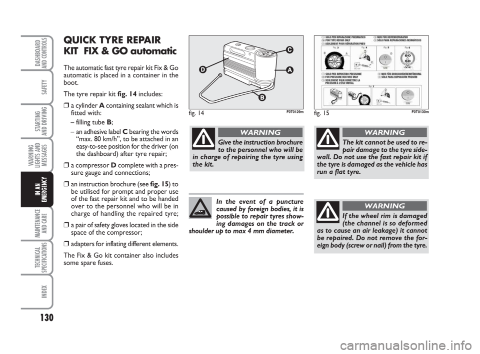
The tyre repair kit fig. 14includes:
❒a cylinder A containing sealant which is
fitted with:
– filling tube B;
– an adhesive label Cbearing the words
“max. 80 km/h”, to be attached in an
easy-to-see position for the driver (on
the dashboard) after tyre repair;
❒a compressor Dcomplete with a pres-
sure gauge and connections;
❒an instruction brochure (see fig. 15) to
be utilised for prompt and proper use
of the fast repair kit and to be handed
over to the personnel who will be in
charge of handling the repaired tyre;
❒a pair of safety gloves located in the side
space of the compressor;
❒adapters for inflating different elements.
The Fix & Go kit container also includes
some spare fuses.
fig. 14F0T0129mfig. 15F0T0130m
Give the instruction brochure
to the personnel who will be
in charge of repairing the tyre using
the kit.
WARNING
The kit cannot be used to re-
pair damage to the tyre side-
wall. Do not use the fast repair kit if
the tyre is damaged as the vehicle has
run a flat tyre.
WARNING
If the wheel rim is damaged
(the channel is so deformed
as to cause an air leakage) it cannot
be repaired. Do not remove the for-
eign body (screw or nail) from the tyre.
WARNINGIn the event of a puncture
caused by foreign bodies, it is
possible to repair tyres show-
ing damages on the track or
shoulder up to max 4 mm diameter.
123-154 Fiorino GB 1ed:123-154 Fiorino GB 1ed 3-12-2009 15:33 Pagina 130
Page 135 of 210
134
SAFETY
MAINTENANCE
AND CARE
TECHNICAL
SPECIFICATIONS
INDEX
DASHBOARDAND CONTROLS
STARTING
AND DRIVING
WARNING
LIGHTS AND
MESSAGES
IN AN
EMERGENCY
WHEN NEEDING
TO CHANGE A BULB
GENERAL INSTRUCTIONS
❒Before changing a bulb check the con-
tacts for oxidation.
❒Burnt bulbs must be replaced by oth-
ers of the same type and power.
❒Always check the height of the head-
light beam after changing a bulb.
❒When a bulb is not working, check that
the corresponding fuse is intact before
replacing it: refer to the “If a fuse
blows” paragraph in this section for the
location of fuses.IMPORTANT A slight misting may appear
on the internal surface of the headlight:
this does not indicate a fault. It is a natur-
al event caused by the low temperature
and the degree of humidity in the air. It will
rapidly disappear when the headlights are
switched on. The presence of drops inside
the headlights indicates infiltration of wa-
ter. Go to a Fiat Dealership.
Modifications or repairs to
the electrical system that are
not carried out properly or do not
take the system technical specifica-
tions into account can cause mal-
functions leading to the risk of fire.
WARNING
Halogen bulbs contain pres-
surised gas which may cause
small fragments of glass to be pro-
jected outwards if the bulb is broken.
WARNING
Halogen lamps must be han-
dled holding the metallic part
only. Touching the transpar-
ent part of the bulb with your
fingers may reduce the intensity of the
emitted light and even compromise du-
ration of the lamp. In case of acciden-
tal contact, rub the lamp with a cloth
and spirit and leave to dry.
If possible, we recommend
that you let the Fiat Dealer-
ship replace the bulbs. Prop-
er operation and orientation
of the external lights are essential for
the safety of the running vehicle, and
for avoiding legal sanctions.
123-154 Fiorino GB 1ed:123-154 Fiorino GB 1ed 3-12-2009 15:33 Pagina 134
Page 146 of 210
145
SAFETY
MAINTENANCE
AND CARE
TECHNICAL
SPECIFICATIONS
INDEX
DASHBOARDAND CONTROLS
STARTING
AND DRIVING
WARNING
LIGHTS AND
MESSAGES
IN AN
EMERGENCY
IF A FUSE BLOWS
GENERAL
Fuses are protective devices for the elec-
tric system: they come into action (i.e. cut
off) mainly due to a fault or improper ac-
tion on the system.
When a specific device does not work cor-
rectly, check the efficiency of the corre-
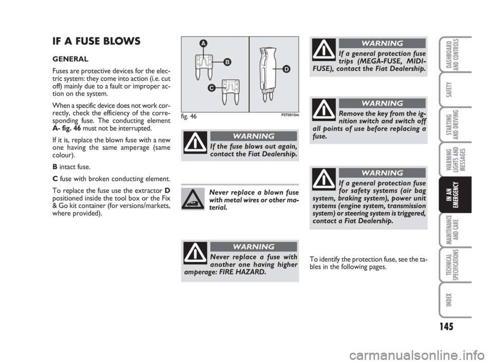
sponding fuse. The conducting element
A- fig. 46must not be interrupted.
If it is, replace the blown fuse with a new
one having the same amperage (same
colour).
Bintact fuse.
Cfuse with broken conducting element.
To replace the fuse use the extractor D
positioned inside the tool box or the Fix
& Go kit container (for versions/markets,
where provided).
If the fuse blows out again,
contact the Fiat Dealership.
WARNING
Never replace a fuse with
another one having higher
amperage: FIRE HAZARD.
WARNING
If a general protection fuse
trips (MEGA-FUSE, MIDI-
FUSE), contact the Fiat Dealership.
WARNING
If a general protection fuse
for safety systems (air bag
system, braking system), power unit
systems (engine system, transmission
system) or steering system is triggered,
contact a Fiat Dealership.
WARNING
Never replace a blown fuse
with metal wires or other ma-
terial.
fig. 46F0T0015m
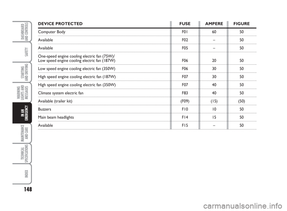
To identify the protection fuse, see the ta-
bles in the following pages.
Remove the key from the ig-
nition switch and switch off
all points of use before replacing a
fuse.
WARNING
123-154 Fiorino GB 1ed:123-154 Fiorino GB 1ed 3-12-2009 15:33 Pagina 145
Page 147 of 210
146
SAFETY
MAINTENANCE
AND CARE
TECHNICAL
SPECIFICATIONS
INDEX
DASHBOARDAND CONTROLS
STARTING
AND DRIVING
WARNING
LIGHTS AND
MESSAGES
IN AN
EMERGENCY
FUSES INSTALLED ON ENGINE
WIRED BOX
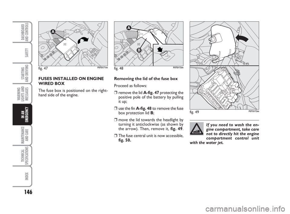
The fuse box is positioned on the right-
hand side of the engine.Removing the lid of the fuse box
Proceed as follows:
❒remove the lid A-fig. 47protecting the
positive pole of the battery by pulling
it up;
❒use the fin A-fig. 48to remove the fuse
box protection lid B;
❒move the lid towards the headlight by
turning it anticlockwise (as shown by
the arrow). Then, remove it, fig. 49.
❒The fuse central unit is now accessible,
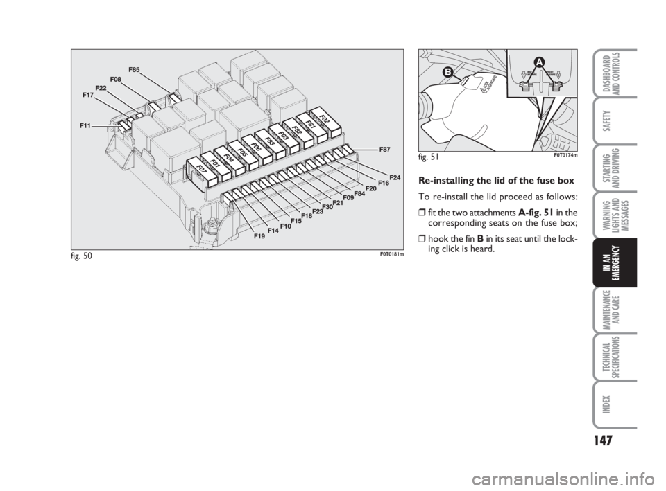
fig. 50.
fig. 47F0T0171mfig. 48F0T0172m
fig. 49F0T0173m
If you need to wash the en-
gine compartment, take care
not to directly hit the engine
compartment control unit
with the water jet.
123-154 Fiorino GB 1ed:123-154 Fiorino GB 1ed 3-12-2009 15:33 Pagina 146
Page 148 of 210
147
SAFETY
MAINTENANCE
AND CARE
TECHNICAL
SPECIFICATIONS
INDEX
DASHBOARDAND CONTROLS
STARTING
AND DRIVING
WARNING
LIGHTS AND
MESSAGES
IN AN
EMERGENCY
Re-installing the lid of the fuse box
To re-install the lid proceed as follows:
❒fit the two attachments A-fig. 51in the
corresponding seats on the fuse box;
❒hook the fin Bin its seat until the lock-
ing click is heard.
fig. 50F0T0181m
fig. 51F0T0174m
123-154 Fiorino GB 1ed:123-154 Fiorino GB 1ed 3-12-2009 15:33 Pagina 147
Page 149 of 210
148
SAFETY
MAINTENANCE
AND CARE
TECHNICAL
SPECIFICATIONS
INDEX
DASHBOARDAND CONTROLS
STARTING
AND DRIVING
WARNING
LIGHTS AND
MESSAGES
IN AN
EMERGENCY
DEVICE PROTECTED FUSE AMPERE FIGURE
Computer Body F01 60 50
Available F02 – 50
Available F05 – 50
One-speed engine cooling electric fan (75W)/
Low speed engine cooling electric fan (187W) F06 20 50
Low speed engine cooling electric fan (350W) F06 30 50
High speed engine cooling electric fan (187W) F07 30 50
High speed engine cooling electric fan (350W) F07 40 50
Climate system electric fan F83 40 50
Available (trailer kit) (F09) (15) (50)
Buzzers F10 10 50
Main beam headlights F14 15 50
Available F15 – 50
123-154 Fiorino GB 1ed:123-154 Fiorino GB 1ed 3-12-2009 15:33 Pagina 148