key FIAT FIORINO 2014 Owner handbook (in English)
[x] Cancel search | Manufacturer: FIAT, Model Year: 2014, Model line: FIORINO, Model: FIAT FIORINO 2014Pages: 210, PDF Size: 4.9 MB
Page 56 of 210
55
SAFETY
STARTING
AND DRIVING
WARNING
LIGHTS AND
MESSAGES
IN AN
EMERGENCY
MAINTENANCE
AND CARE
TECHNICAL
SPECIFICATIONS
INDEX
DASHBOARD
AND CONTROLS
CONTROLS
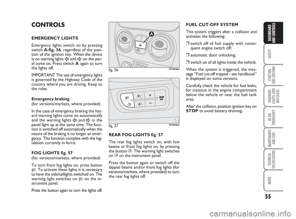
EMERGENCY LIGHTS
Emergency lights switch on by pressing
switch A-fig. 56, regardless of the posi-
tion of the ignition key. When the device
is on warning lights
Îand ¥on the pan-
el come on. Press switch Aagain to turn
the lights off.
IMPORTANT The use of emergency lights
is governed by the Highway Code of the
country where you are driving. Keep to
the rules.
Emergency braking
(for versions/markets, where provided)
In the case of emergency braking the haz-
ard warning lights come on automatically
and the warning lights
Îand ¥in the
panel light up at the same time. The func-
tion is switched off automatically when the
nature of the braking is no longer an emer-
gency. This function complies with the leg-
islation currently in force.
FOG LIGHTS fig. 57
(for versions/markets, where provided)
To turn front fog lights on, press button
5. To activate these lights it is necessary
to have the side/taillights switched on. The
warning light switches on
5on the in-
strument panel.
Press the button again to turn the lights off.REAR FOG LIGHTS fig. 57
The rear fog lights switch on, with low
beams or front fog lights on, by pressing
the button 4. The warning light switches
on 4on the instrument panel.
Press the button again or switch off the
dipped beams and/or front fog lights (for
versions/markets, where provided) to turn
the rear fog lights off.
fig. 56
A
F0T0049m
fig. 57F0T0036m
FUEL CUT-OFF SYSTEM
This system triggers after a collision and
activates the following:
❒switch off of fuel supply with conse-
quent engine switch off;
❒automatic door unlocking;
❒switch on of all lights inside the vehicle.
When the system is triggered, the mes-
sage “Fuel cut-off tripped - see handbook”
is displayed on some versions.
Carefully check the vehicle for fuel leaks,
for instance in the engine compartment
below the vehicle or near the fuel tank
area.
After the collision, position ignition key on
STOPto avoid battery draining.
036-082 Fiorino GB 1ed:036-082 Fiorino GB 1ed 30-11-2009 15:47 Pagina 55
Page 57 of 210
56
SAFETY
STARTING
AND DRIVING
WARNING
LIGHTS AND
MESSAGES
IN AN
EMERGENCY
MAINTENANCE
AND CARE
TECHNICAL
SPECIFICATIONS
INDEX
DASHBOARD
AND CONTROLS
To reset vehicle operation, follow this
procedure:
❒turn the ignition key to MAR;
❒activate the right-hand indicator;
❒deactivate the right-hand indicator;
❒activate the left-hand indicator;
❒deactivate the left-hand indicator;
❒activate the right-hand indicator;
❒deactivate the right-hand indicator;
❒activate the left-hand indicator;
❒deactivate the left-hand indicator;
❒turn the ignition key to STOP.
If, after a crash, you smell fu-
el or notice leaks from the
fuel system, do not reset the system
to avoid fire risk.
WARNING
INTERIOR FITTINGS
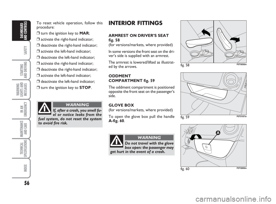
ARMREST ON DRIVER’S SEAT
fig. 58
(for versions/markets, where provided)
In some versions the front seat on the dri-
ver’s side is supplied with an armrest.
The armrest is lowered/lifted as illustrat-
ed by the arrows.
ODDMENT
COMPARTMENT fig. 59
The oddment compartment is positioned
opposite the front seat on the passenger’s
side.
GLOVE BOX
(for versions/markets, where provided)
To open the glove box pull the handle
A-fig. 60.
Do not travel with the glove
box open: the passenger may
get hurt in the event of a crash.
WARNING
fig. 58F0T0056m
fig. 59F0T0187m
fig. 60F0T0069m
036-082 Fiorino GB 1ed:036-082 Fiorino GB 1ed 30-11-2009 15:47 Pagina 56
Page 58 of 210
57
SAFETY
STARTING
AND DRIVING
WARNING
LIGHTS AND
MESSAGES
IN AN
EMERGENCY
MAINTENANCE
AND CARE
TECHNICAL
SPECIFICATIONS
INDEX
DASHBOARD
AND CONTROLS
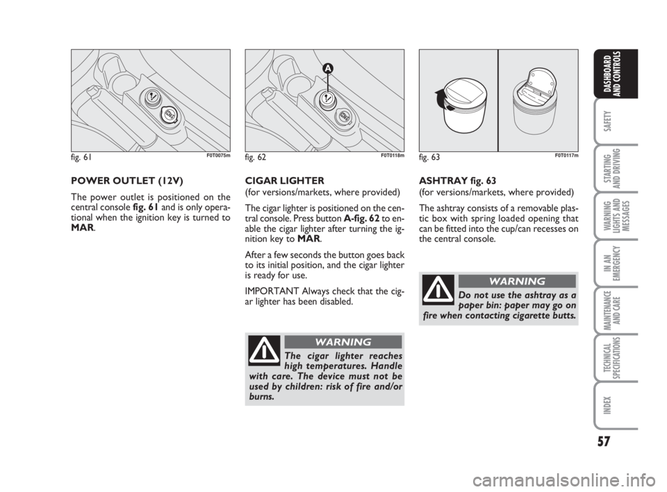
POWER OUTLET (12V)
The power outlet is positioned on the
central console fig. 61and is only opera-
tional when the ignition key is turned to
MAR. CIGAR LIGHTER
(for versions/markets, where provided)
The cigar lighter is positioned on the cen-
tral console. Press button A-fig. 62to en-
able the cigar lighter after turning the ig-
nition key to MAR.
After a few seconds the button goes back
to its initial position, and the cigar lighter
is ready for use.
IMPORTANT Always check that the cig-
ar lighter has been disabled.
fig. 61F0T0075mfig. 62
A
F0T0118m
The cigar lighter reaches
high temperatures. Handle
with care. The device must not be
used by children: risk of fire and/or
burns.
WARNING
fig. 63F0T0117m
ASHTRAY fig. 63
(for versions/markets, where provided)
The ashtray consists of a removable plas-
tic box with spring loaded opening that
can be fitted into the cup/can recesses on
the central console.
Do not use the ashtray as a
paper bin: paper may go on
fire when contacting cigarette butts.
WARNING
036-082 Fiorino GB 1ed:036-082 Fiorino GB 1ed 30-11-2009 15:47 Pagina 57
Page 61 of 210
60
SAFETY
STARTING
AND DRIVING
WARNING
LIGHTS AND
MESSAGES
IN AN
EMERGENCY
MAINTENANCE
AND CARE
TECHNICAL
SPECIFICATIONS
INDEX
DASHBOARD
AND CONTROLS
While refuelling, if the flap is
open, the right-hand side
sliding door cannot be opened.
WARNING
When the vehicle is parked
on a slope, do not block the
sliding door open: any accidental
shock may release the door, thus
leaving it free to move forward.
WARNING
Before leaving the vehicle
parked with sliding doors
open, always check that the latch is
engaged.
WARNING
In Cargo versions the side sliding door is
supplied with a spring loaded latch that
stops the door at the end of its stroke
during opening. Block the door by simply
pushing it to the end of its stroke; release
it by pulling forwards with energy.
In any case, make sure that the door is
properly hooked to the system which
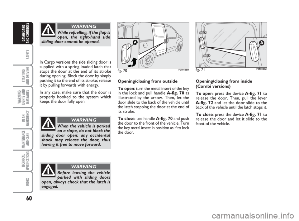
keeps the door fully open.Opening/closing from outside
To open: turn the metal insert of the key
in the lock and pull handle A-fig. 70as
illustrated by the arrow. Then, let the
door slide to the back of the vehicle until
the latch stopping the door at the end of
its stroke.
To close: use handle A-fig. 70and push
the door to the front of the vehicle. Turn
the key metal insert in position as if to lock
the door.
fig. 70F0T0136mfig. 71
A
Opening/closing from inside
(Combi versions)
To open: press the device A-fig. 71to
release the door. Then, pull the lever
A-fig. 72and let the door slide to the
back of the vehicle until the latch stops it.
To close: press the device A-fig. 71to
release the door and let it slide to the
front of the vehicle.
F0T0197m
036-082 Fiorino GB 1ed:036-082 Fiorino GB 1ed 30-11-2009 15:47 Pagina 60
Page 63 of 210
62
SAFETY
STARTING
AND DRIVING
WARNING
LIGHTS AND
MESSAGES
IN AN
EMERGENCY
MAINTENANCE
AND CARE
TECHNICAL
SPECIFICATIONS
INDEX
DASHBOARD
AND CONTROLS
This spring loaded system
has activation forces which
were designed for optimised comfort.
Accidental shocks or a strong wind-
blast may release the springs and let
the door sides close spontaneously.
WARNING
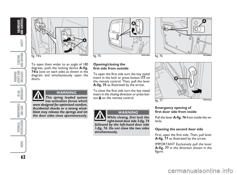
Emergency opening of
first door side from inside
Pull the lever A-fig. 76from inside the ve-
hicle.
Opening the second door side
First, open the first side. Then, pull lever
A-fig. 77 as illustrated by the arrow.
IMPORTANT Exclusively pull the lever
A-fig. 77in the direction shown in the
figure.
fig. 76F0T0060m
Opening/closing the
first side from outside
To open the first side turn the key metal
insert in the lock or press button ∞on
the remote control. Then, pull the lever
A-fig. 75as illustrated by the arrow.
To close the first side turn the key metal
insert in the closing direction or press but-
ton Áon the remote control.
fig. 75F0T0140m
While closing, first lock the
right-hand door side 2-fig. 74
followed by the left-hand door side
1-fig. 74. Do not close the two sides
simultaneously.
WARNING
fig. 77F0T0142m
fig. 74/aF0T0375m
To open them wider to an angle of 180
degrees, push the locking device A-fig.
74/a(one on each side) as shown in the
diagram and simultaneously open the
doors.
036-082 Fiorino GB 1ed:036-082 Fiorino GB 1ed 30-11-2009 15:47 Pagina 62
Page 64 of 210
63
SAFETY
STARTING
AND DRIVING
WARNING
LIGHTS AND
MESSAGES
IN AN
EMERGENCY
MAINTENANCE
AND CARE
TECHNICAL
SPECIFICATIONS
INDEX
DASHBOARD
AND CONTROLS
WINDOW WINDERS
FRONT POWER
WINDOWS
(for versions/markets, where provided)
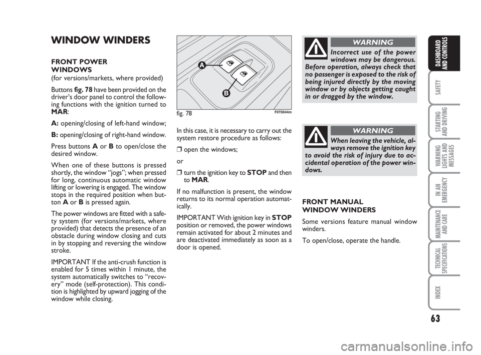
Buttons fig. 78have been provided on the
driver’s door panel to control the follow-
ing functions with the ignition turned to
MAR:
A:opening/closing of left-hand window;
B:opening/closing of right-hand window.
Press buttons Aor Bto open/close the
desired window.
When one of these buttons is pressed
shortly, the window “jogs”; when pressed
for long, continuous automatic window
lifting or lowering is engaged. The window
stops in the required position when but-
ton Aor Bis pressed again.
The power windows are fitted with a safe-
ty system (for versions/markets, where
provided) that detects the presence of an
obstacle during window closing and cuts
in by stopping and reversing the window
stroke.
IMPORTANT If the anti-crush function is
enabled for 5 times within 1 minute, the
system automatically switches to “recov-
ery” mode (self-protection). This condi-
tion is highlighted by upward jogging of the
window while closing.In this case, it is necessary to carry out the
system restore procedure as follows:
❒open the windows;
or
❒turn the ignition key to STOPand then
to MAR.
If no malfunction is present, the window
returns to its normal operation automat-
ically.
IMPORTANT With ignition key in STOP
position or removed, the power windows
remain activated for about 2 minutes and
are deactivated immediately as soon as a
door is opened.
fig. 78F0T0044m
Incorrect use of the power
windows may be dangerous.
Before operation, always check that
no passenger is exposed to the risk of
being injured directly by the moving
window or by objects getting caught
in or dragged by the window.
WARNING
When leaving the vehicle, al-
ways remove the ignition key
to avoid the risk of injury due to ac-
cidental operation of the power win-
dows.
WARNING
FRONT MANUAL
WINDOW WINDERS
Some versions feature manual window
winders.
To open/close, operate the handle.
036-082 Fiorino GB 1ed:036-082 Fiorino GB 1ed 30-11-2009 15:47 Pagina 63
Page 71 of 210
70
SAFETY
STARTING
AND DRIVING
WARNING
LIGHTS AND
MESSAGES
IN AN
EMERGENCY
MAINTENANCE
AND CARE
TECHNICAL
SPECIFICATIONS
INDEX
DASHBOARD
AND CONTROLS
HEADLIGHTS
DIRECTING THE BEAM
Correct direction of the headlights is es-
sential for the comfort and safety of the
driver and the other road users. To en-
sure the best visibility conditions during
travel with the headlights on the vehicle
must have beams aimed correctly. Con-
tact the Fiat Dealership to have the head-
lights checked and properly adjusted.
HEADLIGHT AIMING DEVICE
This device works with the key at MAR
and the dipped beam headlights on.
The vehicle slants backwards when it is
loaded, raising the beam. The beams must
therefore be directed again in this case.FOG LIGHT AIMING DEVICE
(for versions/markets, where provided)
Contact the Fiat Dealership to have the
fog lights checked and properly adjusted.
REGULATING THE BEAMS
ABROAD
Dipped beams factory adjustment depends
on the country where the vehicle is pur-
chased. In countries driving on the left, the
beams are aimed by affixing a purposeful-
ly studied adhesive film in order not to
dazzle the vehicles travelling in the oppo-
site direction. This adhesive film is pro-
vided in Lineaccessori Fiat and is available
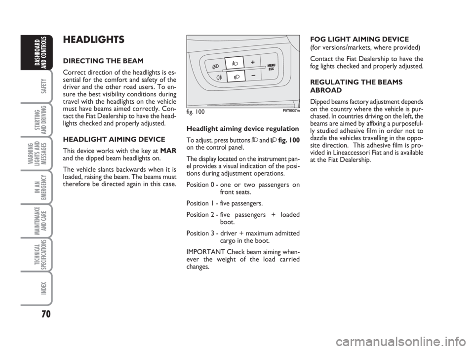
at the Fiat Dealership. Headlight aiming device regulation
To adjust, press buttons Òand
fig. 100
on the control panel.
The display located on the instrument pan-
el provides a visual indication of the posi-
tions during adjustment operations.
Position 0 - one or two passengers on
front seats.
Position 1 - five passengers.
Position 2 - five passengers + loaded
boot.
Position 3 - driver + maximum admitted
cargo in the boot.
IMPORTANT Check beam aiming when-
ever the weight of the load carried
changes.
fig. 100F0T0037m
036-082 Fiorino GB 1ed:036-082 Fiorino GB 1ed 30-11-2009 15:47 Pagina 70
Page 77 of 210
76
SAFETY
STARTING
AND DRIVING
WARNING
LIGHTS AND
MESSAGES
IN AN
EMERGENCY
MAINTENANCE
AND CARE
TECHNICAL
SPECIFICATIONS
INDEX
DASHBOARD
AND CONTROLS
SPEED BLOCK
(for versions/markets, where provided)
The vehicle is available with a speed re-
striction function that can be set, by the
user, at one of 4 pre-set levels: 90, 100,
110, 130 km/h.
To activate/deactivate this function, go to
a Fiat Dealership.
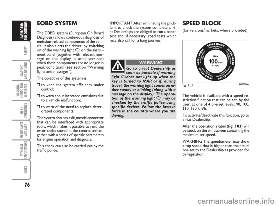
After the operation a label (fig. 103) will
be stuck on the windscreen containing the
maximum set speed.
WARNING The speedometer may show
a top speed that is higher than the actual
one set by the Dealership as provided for
by legislation.
EOBD SYSTEM
The EOBD system (European On Board
Diagnosis) allows continuous diagnosis of
emission-related components of the vehi-
cle. It also alerts the driver, by switching
on of the warning light Uon the instru-
ment panel (together with relevant mes-
sage on the display in some versions)
when these components are no longer in
peak conditions (see section “Warning
lights and messages”).
The objective of this system is:
❒to keep the system efficiency under
control;
❒to warn about increased emissions due
to a vehicle malfunction;
❒to warn of the need to replace deteri-
orated components.
The system also has a diagnostic connector
that can be interfaced with appropriate
tools, which makes it possible to read the
error codes stored in the control unit to-
gether with a series of specific parameters
for engine operation and diagnosis.
This check can also be carried out by the
traffic police.IMPORTANT After eliminating the prob-
lem, to check the system completely, Fi-
at Dealerships are obliged to run a bench
test and, if necessary, road tests which
may also call for a long journey.
Go to a Fiat Dealership as
soon as possible if warning
light Udoes not light up when the
key is turned to MAR or if, during
travel, the warning light comes on ei-
ther steady or blinking (along with a
message on the display). The opera-
tion of the warning light Umay be
checked by the traffic police using
specific devices. Follow the laws in
force in the country where you are
driving.
WARNING
fig. 103F0T0330m
036-082 Fiorino GB 1ed:036-082 Fiorino GB 1ed 30-11-2009 15:47 Pagina 76
Page 82 of 210
81
SAFETY
STARTING
AND DRIVING
WARNING
LIGHTS AND
MESSAGES
IN AN
EMERGENCY
MAINTENANCE
AND CARE
TECHNICAL
SPECIFICATIONS
INDEX
DASHBOARD
AND CONTROLS
DIESEL ENGINES
Operation at low temperatures
If the outside temperature is very low, the
diesel thickens due to the formation of
paraffin clots with consequent anomalous
operation of the fuel supply system.
In order to avoid these problems, different
types of diesel are distributed according to
the season: summer type, winter type and
arctic type (cold, mountain areas). If refu-
elling with diesel fuel whose features are not
suitable to the temperature of use, it is ad-
visable to mix TUTELA DIESEL ART addi-
tive in the proportions shown on the con-
tainer with the fuel. Pour the additive in-
to the tank before the fuel.
When using or parking the vehicle for a
long time in the mountains or cold areas,
it is advisable to refuel using locally avail-
able fuel.
In this case, it is also advisable to keep the
tank over 50% full.For diesel engines, use diesel
fuel for motor vehicles com-
pliant with EN590 European
specifications only. The use of
other products or mixtures may dam-
age the engine beyond repair and con-
sequently cause lapse of warranty in
relation to the damage caused. If you
accidentally introduce other types of
fuel in the tank, do not start the engine
and empty the tank. If the engine has
run also for a very short time, you will
need to have the entire fuel feed sys-
tem emptied in addition to the tank.
REFUELLING CAPACITY
To fill the tank completely, top-up twice
after the pump switches off. Further top-
ups could cause faults in the fuel feeding
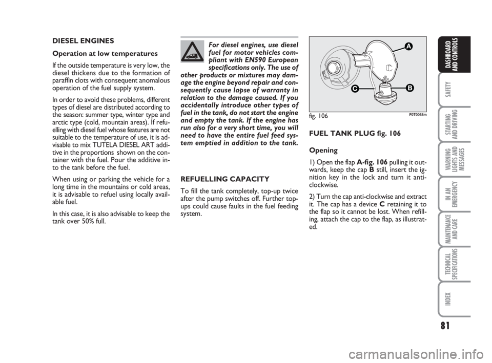
system.FUEL TANK PLUG fig. 106
Opening
1) Open the flap A-fig. 106pulling it out-
wards, keep the cap Bstill, insert the ig-
nition key in the lock and turn it anti-
clockwise.
2) Turn the cap anti-clockwise and extract
it. The cap has a device Cretaining it to
the flap so it cannot be lost. When refill-
ing, attach the cap to the flap, as illustrat-
ed.
fig. 106
C
A
F0T0068m
036-082 Fiorino GB 1ed:036-082 Fiorino GB 1ed 30-11-2009 15:47 Pagina 81
Page 83 of 210
82
SAFETY
STARTING
AND DRIVING
WARNING
LIGHTS AND
MESSAGES
IN AN
EMERGENCY
MAINTENANCE
AND CARE
TECHNICAL
SPECIFICATIONS
INDEX
DASHBOARD
AND CONTROLS
ENVIRONMENTAL
PROTECTION
The devices for curtailing petrol engine
emissions are the following:
❒three-way catalytic converter;
❒Lambda sensors;
❒fuel evaporation prevention system.
In addition, do not let the engine run, even
for a test, with one or more spark plugs
disconnected.
The devices for curtailing diesel fuel en-
gine emissions are the following:
❒oxidising catalytic converter;
❒exhaust gas recirculation system
(E.G.R.);
❒diesel particulate filter (DPF) (for ver-
sions/markets, where provided). Do not place free flames or lit
cigarettes near to the fuel
filler: this may pose a risk of
fire. Keep your face away
from the fuel filler to prevent breath-
ing in harmful vapours.
DIESEL PARTICULATE
FILTER DPF
(Diesel Particulate Filter)
(for versions/markets, where provided)
The Diesel Particulate Filter is a mechan-
ical filter integral with the exhaust system
that physically traps carbon particles pre-
sent in the exhaust gases of Diesel engines.
The diesel particulate filter has been
adopted to eliminate particulates almost
totally in compliance with current / future
law regulations. During normal use of the
vehicle, the engine control unit records a
set of data (e.g.: travel time, type of route,
temperatures, etc.) and it will then calcu-
late the amount of particles trapped by the
filter.
Since this filter physically traps particulates,
it shall be cleaned (reclaimed) at regular
intervals by burning carbon particles. The
regeneration procedure is controlled au-
tomatically by the engine control unit ac-
cording to the filter conditions and the
conditions of use of the vehicle.
During the regeneration procedure, the
following situations may occur: limited in-
crease of idle speed, activation of electric
fan, limited increase of smoke, high tem-
peratures at the exhaust. These events
must not be considered as a malfunction-
ing: they do not impair vehicle behaviour
and the environment. If the dedicated
message is displayed, refer to section
“Warning lights and messages”. Closing
1) Fit the cap (complete with key) and turn
it clockwise until it clicks once or more.
2) Turn the key clockwise and extract it,
then close the flap.
The hermetic seal may cause a slight in-
crease in pressure in the tank. A suction
noise when you release the cap is there-
fore entirely normal.
036-082 Fiorino GB 1ed:036-082 Fiorino GB 1ed 30-11-2009 15:47 Pagina 82