key FIAT FREEMONT 2013 Owner handbook (in English)
[x] Cancel search | Manufacturer: FIAT, Model Year: 2013, Model line: FREEMONT, Model: FIAT FREEMONT 2013Pages: 352, PDF Size: 5.22 MB
Page 145 of 352
SERVICE THE PARKSENSE
®REAR PARK
ASSIST SYSTEM
When the ParkSense
®
Rear Park Assist system is
malfunctioning, the Electronic Vehicle Information
Center (EVIC) will actuate a single chime, once per
ignition cycle, and it will display the “CLEAN PARK
ASSIST”, “SERVICE PARK ASSIST” or “SERVICE PARK
ASSIST SYSTEM” message. Refer to “Electronic Vehicle
Information Center (EVIC)” for further information.
When the shift lever is moved to REVERSE and the
system has detected a fault condition, the EVIC will
display the “CLEAN PARK ASSIST”, “SERVICE PARK
ASSIST” or “SERVICE PARK ASSIST SYSTEM” mes-
sage for as long as the vehicle is in REVERSE. Under this
condition, ParkSense
®will not operate.
If “CLEAN PARK ASSIST” appears in the Electronic
Vehicle Information Center (EVIC) make sure the
outer surface and the underside of the rear fascia/
bumper is clean and clear of snow, ice, mud, dirt or
other obstruction and then cycle the ignition. If the
message continues to appear see an authorized dealer.
If “SERVICE PARK ASSIST SYSTEM” or “SERVICE
PARK ASSIST SYSTEM” appears in the EVIC, see your
authorized dealer.
CLEANING THE PARKSENSE
®SYSTEM
Clean the ParkSense
®
sensors with water, car wash
soap and a soft cloth. Do not use rough or hard cloths. Do not scratch or poke the sensors. Otherwise, you
could damage the sensors.
PARKSENSE
®SYSTEM USAGE
PRECAUTIONS
NOTE:
Ensure that the rear bumper is free of snow, ice,
mud, dirt and debris to keep the ParkSense
®system
operating properly.
Jackhammers, large trucks, and other vibrations could affect the performance of ParkSense®.
When you turn ParkSense
®off, the EVIC will display
“PARK ASSIST SYSTEM OFF.” Furthermore, once
you turn ParkSense
®off, it remains off until you turn
it on again, even if you cycle the ignition key.
When you move the shift lever to the REVERSE position and ParkSense®is turned off, the EVIC will
display the “PARK ASSIST SYSTEM OFF” message
for as long as the vehicle is in REVERSE.
Clean the ParkSense
®sensors regularly, taking care
not to scratch or damage them. The sensors must
not be covered with ice, snow, slush, mud, dirt or
debris. Failure to do so can result in the system not
working properly. The ParkSense
®system might not
detect an obstacle behind the fascia/bumper, or it
139
KNOWING
YOUR
VEHICLE
SAFETY
STARTING
AND
DRIVING
WARNING
LIGHTS
AND
MESSAGES
IN AN
EMERGENCY
SERVICING
AND
CARETECHNICAL
SPECIFICATIONSCONTENTS
Page 148 of 352
WARNING!
Drivers must be careful when backing up
e
ven when using the ParkView
®
Rear
Back Up Camera. Always check carefully behind
your vehicle, and be sure to check for pedestri-
ans, animals, other vehicles, obstructions, or blind
spots before backing up. You are responsible for
the safety of your surroundings and must con-
tinue to pay attention while backing up. Failure
to do so can result in serious injury or death.
To avoid vehicle damage, ParkView
®
should only be used as a parking aid.The
ParkView
®camera is unable to view ev-
ery obstacle or object in your drive path.
To avoid vehicle damage, the vehicle must be
driven slowly when using ParkView
®to be able to
stop in time when an obstacle is seen. It is recom-
mended that the driver look frequently over his/
her shoulder when using ParkView®. NOTE:
If snow, ice, mud, or any foreign substance
builds up on the camera lens, clean the lens, rinse with
water, and dry with a soft cloth. Do not cover the lens.
TURNING PARKVIEW
®ON OR OFF —
WITH TOUCH SCREEN RADIO
1. Turn the Radio on.
2. Press the “More” soft-key.
3. Press the “Settings” soft-key.
4. Press the “Safety & Driving Assistance” soft-key.
5. Press the check box soft key next to “Parkview
®
Backup Camera” to enable/disable.
142
KNOWING YOUR
VEHICLE
SAFETY
S
TARTING AND
DRIVING
WARNING LIGHTSAND
MESSAGES
IN AN
EMERGENCY
SERVICING AND
CARETECHNICAL
SPECIFICATIONSCONTENTS
Page 161 of 352
wear over time through normal use, are specifically not
covered (replacement foam is available for a nominal
charge). UNWIRED TECHNOLOGY IS NOT LIABLE
FOR ANY INJURIES OR DAMAGES TO PERSONS
OR PROPERTY RESULTING FROM THE USE OF, OR
ANY FAILURE OR DEFECT IN, THE PRODUCT,
NOR IS UNWIRED LIABLE FOR ANY GENERAL,
SPECIAL, DIRECT, INDIRECT, INCIDENTAL, CON-
SEQUENTIAL, EXEMPLARY, PUNITIVE OR OTHER
DAMAGES OF ANY KIND OR NATURE WHATSO-
EVER. Some states and jurisdictions may not allow the
exclusion or limitation of incidental or consequential
damages, so the above limitation may not apply to you.
This warranty gives you specific legal rights. You may
also have other rights, which vary from jurisdiction to
jurisdiction.
What Will Unwired
®Do?Unwired
®, at its option,
will repair or replace any defective Product. Unwired
®
reserves the right to replace any discontinued Product
with a comparable model. THIS WARRANTY IS THE
SOLE WARRANTY FOR THIS PRODUCT, SETS
FORTH YOUR EXCLUSIVE REMEDY REGARDING
DEFECTIVE PRODUCTS, AND IS IN LIEU OF ALL
OTHER WARRANTIES (EXPRESS OR IMPLIED), IN-
CLUDING ANY WARRANTY OR MERCHANTABIL-
ITY OR FITNESS FOR A PARTICULAR PURPOSE. Video Screen Operation
Displaying Video
The video screen has two different operating modes, a
video mode (when displaying video such as DVD video,
Aux video, etc.) and an information mode. Because the
VES™ is a dual channel system, Information Mode is
displayed in a split screen format. When in Information
Mode, the left side of the screen is referred to as
Channel 1 and the right side of the screen is referred to
as Channel 2.
Only Channel 1 displays video images. When in video
mode the image is displayed on the full screen, however
Channel 2’s functionality is still available. A popup
banner at the bottom of the screen is displayed mo-
mentarily over the video image. While in video mode
and Channel 2 is selected on the remote control
selector switch, the first remote control key press will
activate the popup banner indicating Channel 2’s sta-
tus. While the banner is still visible, any subsequent
remote control key press for Channel 2 shall initiate
the requested remote control command. (fig. 110)
In a two-screen system, the video for Channel 1 is
displayed on the first rear seat screen and the video for
Channel 2 is displayed on the second rear seat screen.
Information Mode is displayed in split screen, the left
side of the screen (Channel 1) shows the status/mode
of the first rear seat screen and the right side of the
155
KNOWING
YOUR
VEHICLE
SAFETY
S
TARTING
AND
DRIVING
WARNING
LIGHTS
AND
MESSAGES
IN AN
EMERGENCY
SERVICING
AND
CARETECHNICAL
SPECIFICATIONSCONTENTS
Page 164 of 352
audio for Channel 1 has been muted using the
remote control’s MUTE button.
3. Channel 2 Audio Only/Mute — Audio: Only in a single screen system: The audio only icon is dis-
played on Channel 2 when Channel 1 is in a video
mode. Mute: when the Mute icon is displayed, the
audio for Channel 2 has been muted using the
remote control’s MUTE button.
4. Channel 2 Mode — Displays the current source for Channel 2.
5. Channel 2 ENTER Button Action — When the ENTER button on the remote control is pressed
with the "INPUT FILE #" button visible on the
screen, the screen shows a numeric entry keypad
which allows you to enter a specific track number
on data discs and HDD (see Numeric Keypad Menu
section of this manual). Also, Enter Button Action –
“INPUT TRK #” to enter a specific track number on
audio discs.
6. Remote Locked Out — When the icon is displayed, the remote control functions are disabled.
7. Clock — Displays the time.
8. Channel 1 Shared Status — When the icon is displayed, the audio for Channel 1 is also shared
with the radio and playing through the cabin speak-
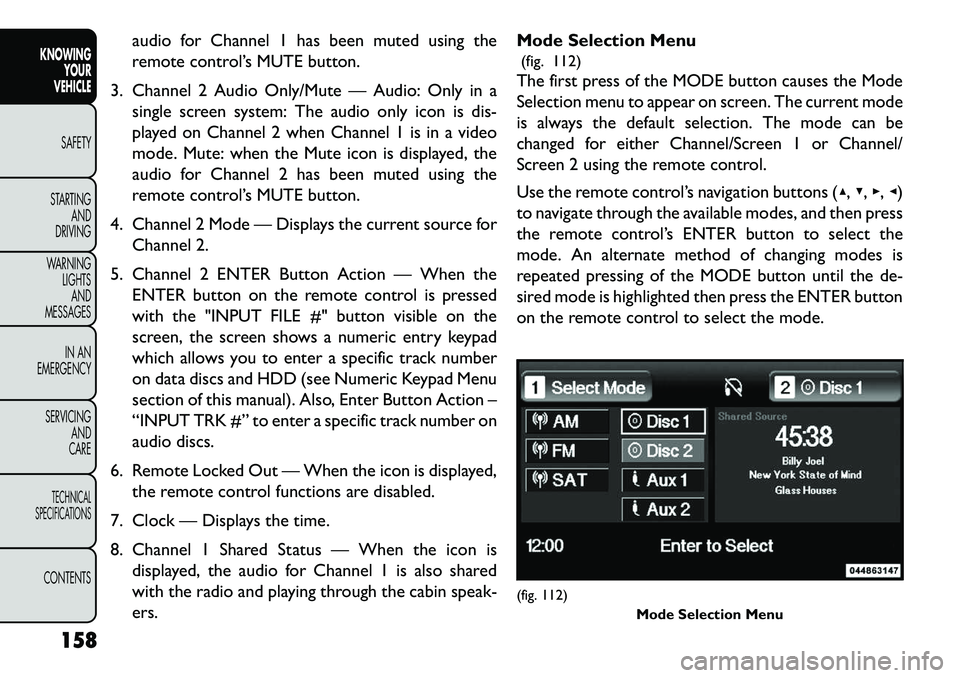
ers. Mode Selection Menu
(fig. 112)
The first press of the MODE button causes the Mode
Selection menu to appear on screen. The current mode
is always the default selection. The mode can be
changed for either Channel/Screen 1 or Channel/
Screen 2 using the remote control.
Use the remote control’s navigation buttons (▴, ▾,▸,◂)
to navigate through the available modes, and then press
the remote control’s ENTER button to select the
mode. An alternate method of changing modes is
repeated pressing of the MODE button until the de-
sired mode is highlighted then press the ENTER button
on the remote control to select the mode.
(fig. 112) Mode Selection Menu
158
KNOWING YOUR
VEHICLE
SAFETY
S
TARTING AND
DRIVING
WARNING LIGHTSAND
MESSAGES
IN AN
EMERGENCY
SERVICING AND
CARETECHNICAL
SPECIFICATIONSCONTENTS
Page 165 of 352
In a single screen system, when a video mode (such as
DVD-video, Aux video, etc.) is active and Channel/
Screen 1 is selected using the remote control selector
switch, the first press of the remote control’s MODE
button causes the Mode Selection menu to appear.
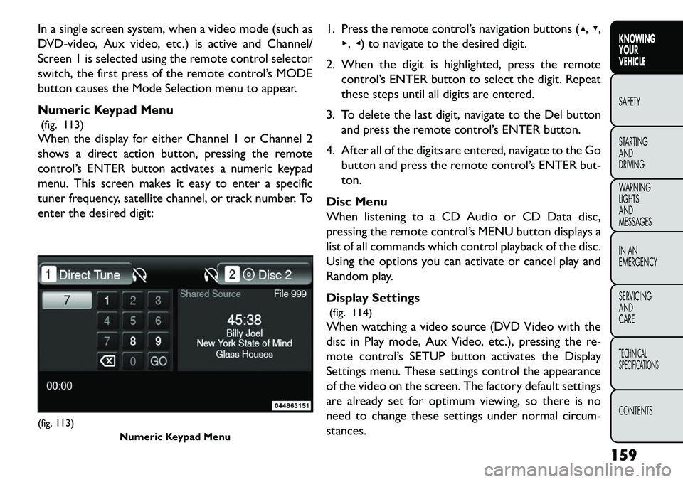
Numeric Keypad Menu(fig. 113)
When the display for either Channel 1 or Channel 2
shows a direct action button, pressing the remote
control’s ENTER button activates a numeric keypad
menu. This screen makes it easy to enter a specific
tuner frequency, satellite channel, or track number. To
enter the desired digit: 1. Press the remote control’s navigation buttons (▴,
▾,
▸, ◂) to navigate to the desired digit.
2. When the digit is highlighted, press the remote control’s ENTER button to select the digit. Repeat
these steps until all digits are entered.
3. To delete the last digit, navigate to the Del button and press the remote control’s ENTER button.
4. After all of the digits are entered, navigate to the Go button and press the remote control’s ENTER but-
ton.
Disc Menu
When listening to a CD Audio or CD Data disc,
pressing the remote control’s MENU button displays a
list of all commands which control playback of the disc.
Using the options you can activate or cancel play and
Random play.
Display Settings (fig. 114)
When watching a video source (DVD Video with the
disc in Play mode, Aux Video, etc.), pressing the re-
mote control’s SETUP button activates the Display
Settings menu. These settings control the appearance
of the video on the screen. The factory default settings
are already set for optimum viewing, so there is no
need to change these settings under normal circum-
stances.(fig. 113) Numeric Keypad Menu
159
KNOWING
YOUR
VEHICLE
SAFETY
S
TARTING
AND
DRIVING
WARNING
LIGHTS
AND
MESSAGES
IN AN
EMERGENCY
SERVICING
AND
CARETECHNICAL
SPECIFICATIONSCONTENTS
Page 169 of 352
RADIO OPERATION AND MOBILE
PHONES
Under certain conditions, the mobile phone being on in
your vehicle can cause erratic or noisy performance
from your radio. This condition may be lessened or
eliminated by relocating the mobile phone antenna.
This condition is not harmful to the radio. If your radio
performance does not satisfactorily “clear” by the
repositioning of the antenna, it is recommended that
the radio volume be turned down or off during mobile
phone operation.ADDING FUEL
FUEL FILLER CAP (GAS CAP) (for
versions/markets, where provided)
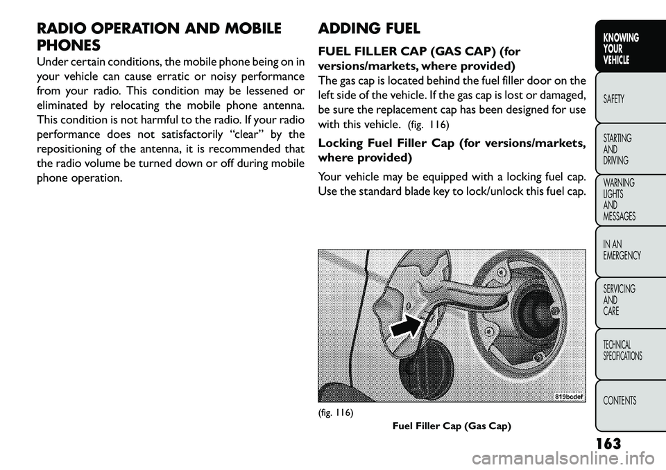
The gas cap is located behind the fuel filler door on the
left side of the vehicle. If the gas cap is lost or damaged,
be sure the replacement cap has been designed for use
with this vehicle.
(fig. 116)
Locking Fuel Filler Cap (for versions/markets,
where provided)
Your vehicle may be equipped with a locking fuel cap.
Use the standard blade key to lock/unlock this fuel cap.
(fig. 116) Fuel Filler Cap (Gas Cap)
163
KNOWING
YOUR
VEHICLE
SAFETY
S
TARTING
AND
DRIVING
WARNING
LIGHTS
AND
MESSAGES
IN AN
EMERGENCY
SERVICING
AND
CARETECHNICAL
SPECIFICATIONSCONTENTS
Page 180 of 352
ACTIVE HOOD SYSTEM (for versions/
markets, where provided)
The Active Hood system is intended to enhance pe-
destrian protection by elevating the vehicle’s hood
upon an impact with a pedestrian or other object. The
system is automatically activated when the vehicle is
moving within a specified vehicle speed range. In order
to detect a range of pedestrians, other objects that are
impacted may result in an Active Hood deployment.
Deployment Sensors And Controls
The Electronic Pedestrian Protection Module (EPPM)
determines if deployment of the actuators in a frontal
impact is required. Based on the impact sensors signals,
the EPPM determines when to deploy the actuators.
The impact sensors are located within the front bum-
per area.
The EPPM monitors the readiness of the electronic
parts of the Active Hood system whenever the ignition
switch is in the START or ON/RUN position. If the key
is in the LOCK position, in the ACC position, or not in
the ignition, the Active Hood system is not on and the
Active Hood will not deploy.
The EPPM contains a backup power supply system that
may deploy the actuators even if the battery loses
power or it becomes disconnected prior to deploy-
ment.Service Active Hood System
If the EPPM has deployed the Active Hood, or if it
detects a malfunction in any part of the system, it turns
on the Air Bag Warning Light and it will display the
“SERVICE ACTIVE HOOD” message in the Electronic
Vehicle Information Center (EVIC), for versions/
markets, where provided. A single chime will sound if
the Air Bag Warning Light comes on again after initial
startup. It also includes diagnostics that will illuminate
the Air Bag Warning Light if a malfunction is noted that
could affect the Active Hood system. The diagnostics
also record the nature of the malfunction. If the Air Bag
Warning Light is illuminated, or if “SERVICE ACTIVE
HOOD” appears in the EVIC, see your authorized
dealer.
In the event of an Active Hood deployment, the vehicle
should be serviced by an authorized dealer. The hood
hinges must be serviced and the actuator assemblies
replaced to restore system functionality.
Following an Active Hood deployment, the hood posi-
tion can be temporarily reset by pushing down at the
rear edge over the hood hinges as the internal pressure
of each actuator is relieved. The temporary hood reset
position is intended to improve forward driving visibil-
ity over the hood until the vehicle can be serviced. The
temporary hood reset position will leave the hood
174
KNOWING YOUR
VEHICLE
SAFETY
STARTING AND
DRIVING
W
ARNING LIGHTS AND
MESSAGES
IN AN
EMERGENCY
SERVICING AND
CARETECHNICAL
SPECIFICATIONSCONTENTS
Page 184 of 352
Mass GroupSeating Position (or other site)
Front
Passenger Rear Outboard Rear Center Intermediate
Outboard Intermediate
Center
Group — up to 10 kg X*U N/A**UU
Group 0+ — up to 13 kg X*U N/A**UU
Group 1 – 9 to 18 kg X*U N/A**UU
Group II – 15 to 25 kg X*U N/A**UU
Group III — 22 to 36 kg X*U N/A**UU
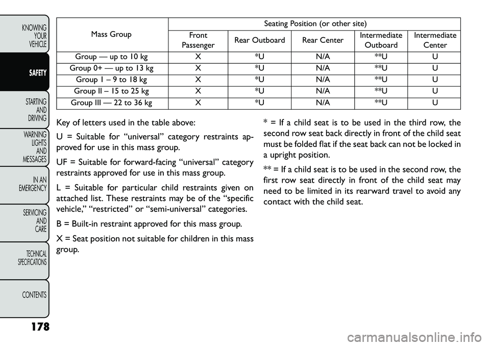
Key of letters used in the table above:
U = Suitable for “universal” category restraints ap-
proved for use in this mass group.
UF = Suitable for forward-facing “universal” category
restraints approved for use in this mass group.
L = Suitable for particular child restraints given on
attached list. These restraints may be of the “specific
vehicle,” “restricted” or “semi-universal” categories.
B = Built-in restraint approved for this mass group.
X = Seat position not suitable for children in this mass
group. * = If a child seat is to be used in the third row, the
second row seat back directly in front of the child seat
must be folded flat if the seat back can not be locked in
a upright position.
** = If a child seat is to be used in the second row, the
first row seat directly in front of the child seat may
need to be limited in its rearward travel to avoid any
contact with the child seat.
178
KNOWING YOUR
VEHICLE
SAFETY
STARTING AND
DRIVING
W
ARNING LIGHTS AND
MESSAGES
IN AN
EMERGENCY
SERVICING AND
CARETECHNICAL
SPECIFICATIONSCONTENTS
Page 186 of 352
Key of letters used in the table above:
(1) = For the CRS which do not carry the ISO/XX size
class identification (A to G), for the applicable mass
group, the car manufacturer shall indicate the vehicle
specific ISOFIX child restraint system(s) recommended
for each position.
IUF = Suitable for ISOFIX forward child restraints
systems of universal category approved for use in the
mass group.
IL = Suitable for particular ISOFIX child restraint sys-
tems (CRS) given in the attached list. These ISOFIX
CRS are those of the “specific vehicle”, “restricted” or
“semi-universal” catagories.
X = ISOFIX position not suitable for ISOFIX child
restraint systems in this mass group and / or this size
class.
* = Seats in front of child restraint seats may need to be
adjusted forward to install the child restraint seat.
** = No access to 3rd row seating positions if Carrycot
is installed in vehicle.
There are different sizes and types of restraints for
children from newborn size to the child almost large
enough for an adult safety belt. Always check the child
seat Owner's Manual to ensure you have the correctseat for your child. Use the restraint that is correct for
your child.
Infants And Child Restraints
Safety experts recommend that children ride
rearward-facing in the vehicle until they are two years
old or until they reach either the height or weight limit
of their rear facing child safety seat. Two types of child
restraints can be used rearward-facing: infant carriers
and convertible child seats.
The infant carrier is only used rearward-facing in the
vehicle. It is recommended for children from birth until
they reach the weight or height limit of the infant
carrier. Convertible child seats can be used either
rearward-facing or forward-facing in the vehicle. Con-
vertible child seats often have a higher weight limit in
the rearward-facing direction than infant carriers do, so
they can be used rearward-facing by children who have
outgrown their infant carrier but are still less than at
least two years old. Children should remain rearward-
facing until they reach the highest weight or height
allowed by their convertible child seat. Both types of
child restraints are held in the vehicle by the lap/
shoulder belt or the ISOFIX child restraint anchor
system. Refer to “ISOFIX — Child Seat Anchorage
System”.
180
KNOWING YOUR
VEHICLE
SAFETY
STARTING AND
DRIVING
W
ARNING LIGHTS AND
MESSAGES
IN AN
EMERGENCY
SERVICING AND
CARETECHNICAL
SPECIFICATIONSCONTENTS
Page 201 of 352
NOTE:In a rollover the pretensioners and/or SAB
and SABIC air bags may deploy on both sides of the
vehicle.
Front And Side Impact Sensors
In front and side impacts, impact sensors can aid the
ORC in determining appropriate response to impact
events.
Enhanced Accident Response System
In the event of an impact causing air bag deployment, if
the communication network remains intact, and the
power remains intact, depending on the nature of the
event the ORC will determine whether to have the
Enhanced Accident Response System perform the fol-
lowing functions:
Cut off fuel to the engine.
Flash hazard lights as long as the battery has power or until the ignition is cycled off.
Turn on the interior lights, which remain on as long as the battery has power or until the ignition key is
removed.
Unlock the doors automatically.
In order to reset the Enhanced Accident Response
System functions after an event, the ignition switch
must be changed from IGN ON to IGN OFF. If A Deployment Occurs
The Advanced Front Air Bags are designed to deflate
immediately after deployment.
NOTE:
Front and/or side air bags will not deploy in
all collisions. This does not mean something is wrong
with the air bag system.
If you do have a collision which deploys the air bags, any
or all of the following may occur:
The nylon air bag material may sometimes cause abrasions and/or skin reddening to the driver and
front passenger as the air bags deploy and unfold.
The abrasions are similar to friction rope burns or
those you might get sliding along a carpet or gymna-
sium floor. They are not caused by contact with
chemicals. They are not permanent and normally
heal quickly. However, if you haven't healed signifi-
cantly within a few days, or if you have any blistering,
see your doctor immediately.
As the air bags deflate, you may see some smoke-like particles. The particles are a normal by-product of
the process that generates the non-toxic gas used for
air bag inflation. These airborne particles may irritate
the skin, eyes, nose, or throat. If you have skin or eye
irritation, rinse the area with cool water. For nose or
throat irritation, move to fresh air. If the irritation
continues, see your doctor. If these particles settle
195
KNOWING
YOUR
VEHICLE
SAFETY
STARTING
AND
DRIVING
W
ARNING
LIGHTS
AND
MESSAGES
IN AN
EMERGENCY
SERVICING
AND
CARETECHNICAL
SPECIFICATIONSCONTENTS