battery FIAT FREEMONT 2013 Owner handbook (in English)
[x] Cancel search | Manufacturer: FIAT, Model Year: 2013, Model line: FREEMONT, Model: FIAT FREEMONT 2013Pages: 352, PDF Size: 5.22 MB
Page 15 of 352
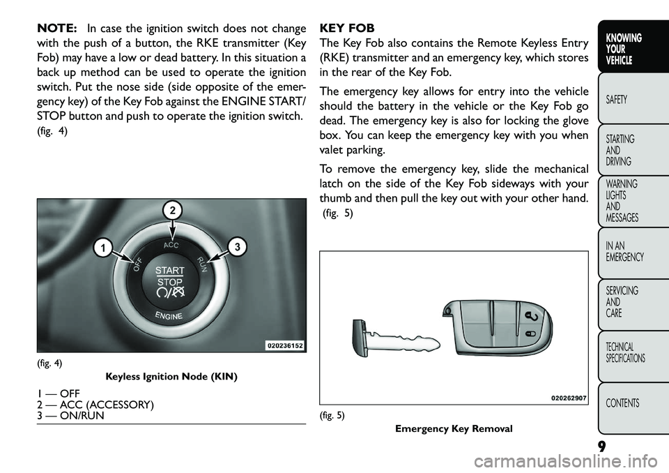
NOTE:In case the ignition switch does not change
with the push of a button, the RKE transmitter (Key
Fob) may have a low or dead battery. In this situation a
back up method can be used to operate the ignition
switch. Put the nose side (side opposite of the emer-
gency key) of the Key Fob against the ENGINE START/
STOP button and push to operate the ignition switch.
(fig. 4) KEY FOB
The Key Fob also contains the Remote Keyless Entry
(RKE) transmitter and an emergency key, which stores
in the rear of the Key Fob.
The emergency key allows for entry into the vehicle
should the battery in the vehicle or the Key Fob go
dead. The emergency key is also for locking the glove
box. You can keep the emergency key with you when
valet parking.
To remove the emergency key, slide the mechanical
latch on the side of the Key Fob sideways with your
thumb and then pull the key out with your other hand.
(fig. 5)(fig. 4) Keyless Ignition Node (KIN)1 — OFF
2 — ACC (ACCESSORY)
3 — ON/RUN
(fig. 5)
Emergency Key Removal
9
KNOWING
YOUR
VEHICLE
SAFETY
S
TARTING
AND
DRIVING
WARNING
LIGHTS
AND
MESSAGES
IN AN
EMERGENCY
SERVICING
AND
CARETECHNICAL
SPECIFICATIONSCONTENTS
Page 19 of 352
turn signal lights will flash to acknowledge the unlock
signal. The illuminated entry system will also turn on.
If the vehicle is equipped with Passive Entry, refer to
“Keyless EnterNGo™ (for versions/markets, where
provided)” under “Knowing Your Vehicle” for further
information.
Remote Key Unlock, Driver Door/All Doors
1st Press
This feature lets you program the system to unlock
either the driver's door or all doors on the first press of
the UNLOCK button on the RKE transmitter. To
change the current setting, refer to “Uconnect
Touch™ Settings” in “Knowing Your Vehicle” for fur-
ther information.
Flash Lights With Lock
This feature will cause the turn signal lights to flash
when the doors are locked or unlocked with the RKE
transmitter. This feature can be turned on or turned
off. To change the current setting, refer to “Uconnect
Touch™ Settings” in “Knowing Your Vehicle” for fur-
ther information.
Turn Headlights On With Remote Key Unlock
This feature activates the headlights for up to 90
seconds when the doors are unlocked with the RKE
transmitter. The time for this feature is programmable
on vehicles equipped through Uconnect Touch™. Tochange the current setting, refer to “Uconnect
Touch™ Settings” in “Knowing Your Vehicle” for fur-
ther information.
TO LOCK THE DOORS AND LIFTGATE
Press and release the LOCK button on the RKE trans-
mitter to lock all doors and liftgate. The turn signal
lights will flash to acknowledge the signal.
If the vehicle is equipped with Passive Entry, refer to
“Keyless EnterNGo™ (for versions/markets, where
provided)” under “Knowing Your Vehicle” for further
information.
Programming Additional Transmitters
Programming Key Fobs or RKE transmitters may be
performed at an authorized dealer.
TRANSMITTER BATTERY REPLACEMENT
The recommended replacement battery is one
CR2032 battery.
NOTE:
Perchlorate Material — special handling may apply.
Batteries could contain dangerous materials. Please
dispose of them according to respect for environ-
ment and local laws.
Used batteries are harmful to the environment. You can dispose of them either in the correct containers
13
KNOWING
YOUR
VEHICLE
SAFETY
STARTING
AND
DRIVING
WARNING
LIGHTS
AND
MESSAGES
IN AN
EMERGENCY
SERVICING
AND
CARETECHNICAL
SPECIFICATIONSCONTENTS
Page 20 of 352
as specified by law or by taking them to a FIAT
Dealership, which will deal with their disposal.
Do not touch the battery terminals that are on the back housing or the printed circuit board.
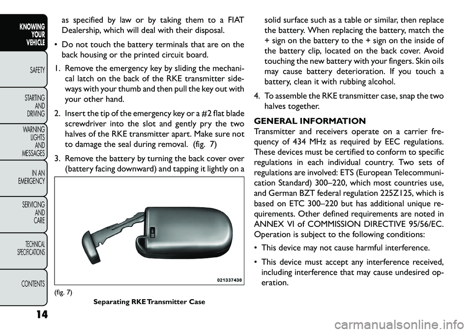
1. Remove the emergency key by sliding the mechani- cal latch on the back of the RKE transmitter side-
ways with your thumb and then pull the key out with
your other hand.
2. Insert the tip of the emergency key or a #2 flat blade screwdriver into the slot and gently pry the two
halves of the RKE transmitter apart. Make sure not
to damage the seal during removal. (fig. 7)
3. Remove the battery by turning the back cover over (battery facing downward) and tapping it lightly on a solid surface such as a table or similar, then replace
the battery. When replacing the battery, match the
+ sign on the battery to the + sign on the inside of
the battery clip, located on the back cover. Avoid
touching the new battery with your fingers. Skin oils
may cause battery deterioration. If you touch a
battery, clean it with rubbing alcohol.
4. To assemble the RKE transmitter case, snap the two halves together.
GENERAL INFORMATION
Transmitter and receivers operate on a carrier fre-
quency of 434 MHz as required by EEC regulations.
These devices must be certified to conform to specific
regulations in each individual country. Two sets of
regulations are involved: ETS (European Telecommuni-
cation Standard) 300–220, which most countries use,
and German BZT federal regulation 225Z125, which is
based on ETC 300–220 but has additional unique re-
quirements. Other defined requirements are noted in
ANNEX VI of COMMISSION DIRECTIVE 95/56/EC.
Operation is subject to the following conditions:
This device may not cause harmful interference.
This device must accept any interference received, including interference that may cause undesired op-
eration.(fig. 7) Separating RKE Transmitter Case
14
KNOWING YOUR
VEHICLE
SAFETY
S
TARTING AND
DRIVING
WARNING LIGHTSAND
MESSAGES
IN AN
EMERGENCY
SERVICING AND
CARETECHNICAL
SPECIFICATIONSCONTENTS
Page 21 of 352
If your RKE transmitter fails to operate from a normal
distance, check for these two conditions:
1. A weak battery in the transmitter. The expected lifeof the battery is a minimum of three years.
2. Closeness to a radio transmitter such as a radio station tower, airport transmitter, and some mobile
or CB radios. VEHICLE SECURITY ALARM
The Vehicle Security Alarm (VSA) system monitors the
vehicle doors, hood, and liftgate for unauthorized en-
try and the ignition switch for unauthorized operation.
If something triggers the alarm, the system will sound
the horn intermittently, flash the headlights and tail-
lights, and flash the Vehicle Security Light in the instru-
ment cluster.
REARMING OF THE SYSTEM
If something triggers the alarm, and no action is taken
to disarm it, the system will turn off the horn after
approximately 29 seconds, turn off all of the visual
signals after one minute, and then the system will
rearm itself.
TO ARM THE SYSTEM
Follow these steps to arm the Vehicle Security Alarm:
1. Make sure the vehicle ignition system is "OFF".
(refer to "Starting Procedures" in "Starting And
Driving" for further information).
2. Perform one of the following methods to lock the vehicle:
Press LOCK on the interior power door lock
switch with the driver and/or passenger door open.
Press the LOCK button on the exterior Passive
Entry Door Handle with a valid Key Fob available in
15
KNOWING
YOUR
VEHICLE
SAFETY
S
TARTING
AND
DRIVING
WARNING
LIGHTS
AND
MESSAGES
IN AN
EMERGENCY
SERVICING
AND
CARETECHNICAL
SPECIFICATIONSCONTENTS
Page 22 of 352
the same exterior zone (refer to "Keyless Enter-N-
Go™" in "Knowing Your Vehicle" for further infor-
mation).
Press the LOCK button on the Remote Keyless
Entry (RKE) transmitter.
3. If any doors are open, close them.
TO DISARM THE SYSTEM
The Vehicle Security Alarm can be disarmed using any
of the following methods:
Press the UNLOCK button on the Remote Keyless Entry (RKE) transmitter.
Grasp the Passive Entry Unlock Door Handle with a valid key fob available in the same exterior zone
(refer to "Keyless EnterNGo™" in "Knowing Your
Vehicle" for further information).
Cycle the vehicle ignition system out of the OFF position by pressing the Keyless EnterNGo™
Start/Stop button (requires at least one valid Key Fob
in the vehicle).
NOTE:
The driver's door key cylinder and the liftgate button on the RKE transmitter cannot arm or disarm the
Vehicle Security Alarm. The Vehicle Security Alarm remains armed during
power liftgate entry. Pressing the liftgate button will
not disarm the Vehicle Security Alarm. If someone
enters the vehicle through the liftgate and opens any
door the alarm will sound.
When the Vehicle Security Alarm is armed, the interior power door lock switches will not unlock
the doors.
The Vehicle Security Alarm is designed to protect your
vehicle; however, you can create conditions where the
system will give you a false alarm. If one of the previ-
ously described arming sequences has occurred, the
Vehicle Security Alarm will arm regardless of whether
you are in the vehicle or not. If you remain in the
vehicle and open a door, the alarm will sound. If this
occurs, disarm the Vehicle Security Alarm.
If the Vehicle Security Alarm is armed and the battery
becomes disconnected, the Vehicle Security Alarm will
remain armed when the battery is reconnected; the
exterior lights will flash, the horn will sound. If this
occurs, disarm the Vehicle Security Alarm.
SECURITY SYSTEM MANUAL OVERRIDE
The Vehicle Security Alarm will not arm if you lock the
doors using the manual door lock plunger.
16
KNOWING YOUR
VEHICLE
SAFETY
S
TARTING AND
DRIVING
WARNING LIGHTSAND
MESSAGES
IN AN
EMERGENCY
SERVICING AND
CARETECHNICAL
SPECIFICATIONSCONTENTS
Page 24 of 352
TO DISARM THE SYSTEM
The Vehicle Security Alarm can be disarmed using any
of the following methods:
Press the UNLOCK button on the Remote KeylessEntry (RKE) transmitter.
Grasp the Passive Entry Unlock Door Handle with a valid key fob available in the same exterior zone
(refer to "Keyless EnterNGo™" in "Knowing Your
Vehicle" for further information).
Cycle the vehicle ignition system out of the OFF position by pressing the Keyless EnterNGo™
Start/Stop button (requires at least one valid Key Fob
in the vehicle).
NOTE:
The driver's door key cylinder and the liftgate button on the RKE transmitter cannot arm or disarm the
Vehicle Security Alarm.
When the Vehicle Security Alarm is armed, the interior power door lock switches will not unlock
the doors. The Vehicle Security Alarm is designed to protect your
vehicle; however, you can create conditions where the
system will give you a false alarm. If one of the previ-
ously described arming sequences has occurred, the
Vehicle Security Alarm will arm regardless of whether
you are in the vehicle or not. If you remain in the
vehicle and open a door, the alarm will sound. If this
occurs, disarm the Vehicle Security Alarm.
If the Vehicle Security Alarm is armed and the battery
becomes disconnected, the Vehicle Security Alarm will
remain armed when the battery is reconnected; the
exterior lights will flash, the horn will sound. If this
occurs, disarm the Vehicle Security Alarm.
SECURITY SYSTEM MANUAL OVERRIDE
The system will not arm if you lock the doors using the
manual door lock plunger.
18
KNOWING YOUR
VEHICLE
SAFETY
S
TARTING AND
DRIVING
WARNING LIGHTSAND
MESSAGES
IN AN
EMERGENCY
SERVICING AND
CARETECHNICAL
SPECIFICATIONSCONTENTS
Page 27 of 352

menu. The main display area also displays "pop up"
messages that consist of approximately 60 possible
warning or information messages. These pop up mes-
sages fall into several categories:
Five Second Stored Messages
When the appropriate conditions occur, this type of
message takes control of the main display area for five
seconds and then returns to the previous screen. Most
of the messages of this type are then stored (as long as
the condition that activated it remains active) and can
be reviewed from the "Messages" main menu item. As
long as there is a stored message, an "i" will be displayed
in the EVIC's compass/outside temp line. Examples of
this message type are "Right Front Turn Signal Lamp
Out" and "Low Tire Pressure".
Unstored Messages
This message type is displayed indefinitely or until the
condition that activated the message is cleared. Ex-
amples of this message type are "Turn Signal On" (if a
turn signal is left on) and "Lights On" (if driver leaves
the vehicle).
Unstored Messages Until RUN
This message type is displayed until the ignition is in the
RUN state. Example of this message type is "Press
Brake Pedal and Push Button to Start". Five Second Unstored Messages
When the appropriate conditions occur, this type of
message takes control of the main display area for five
seconds and then returns to the previous screen.
Examples of this message type are "Memory System
Unavailable - Not in Park" and "Automatic High Beams
On".
The Reconfigurable Telltales section is divided into the
white telltales area on the right, amber telltales in the
middle, and red telltales on the left.
When the appropriate conditions exist, the EVIC dis-
plays the following messages:
Turn Signal On (with a continuous warning chime if
the vehicle is driven more than 1.6 km with either
turn signal on)
Left Front Turn Signal Light Out (with a single chime)
Left Rear Turn Signal Light Out (with a single chime)
Right Front Turn Signal Light Out (with a single chime)
Right Rear Turn Signal Light Out (with a single chime)
RKE Battery Low (with a single chime)
Personal Settings Not Available – Vehicle Not in PARK (for versions/markets, where provided)
21
KNOWING
YOUR
VEHICLE
SAFETY
STARTING
AND
DRIVING
WARNING
LIGHTS
AND
MESSAGES
IN AN
EMERGENCY
SERVICING
AND
CARETECHNICAL
SPECIFICATIONSCONTENTS
Page 84 of 352
INTERIOR LIGHTS
The interior lights come on when a door is opened.
To protect the battery, the interior lights will turn off
automatically 10 minutes after the ignition switch is
moved to the LOCK position. This will occur if the
interior lights were switched on manually or are on
because a door is open. This includes the glove box
light, but not the trunk light. To restore interior light
operation, either turn the ignition switch ON or cycle
the light switch.
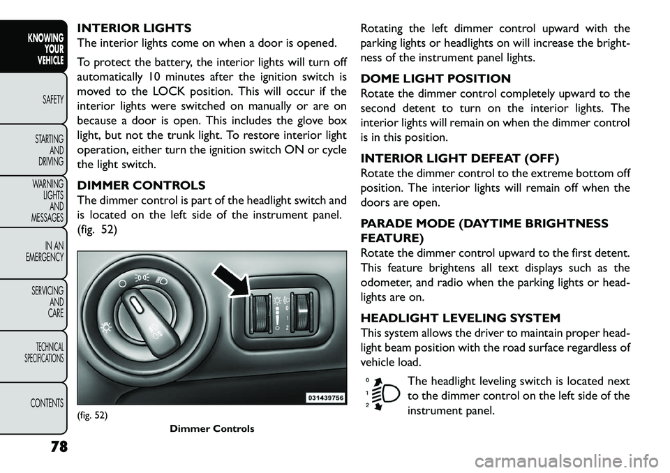
DIMMER CONTROLS
The dimmer control is part of the headlight switch and
is located on the left side of the instrument panel.
(fig. 52)Rotating the left dimmer control upward with the
parking lights or headlights on will increase the bright-
ness of the instrument panel lights.
DOME LIGHT POSITION
Rotate the dimmer control completely upward to the
second detent to turn on the interior lights. The
interior lights will remain on when the dimmer control
is in this position.
INTERIOR LIGHT DEFEAT (OFF)
Rotate the dimmer control to the extreme bottom off
position. The interior lights will remain off when the
doors are open.
PARADE MODE (DAYTIME BRIGHTNESS
FEATURE)
Rotate the dimmer control upward to the first detent.
This feature brightens all text displays such as the
odometer, and radio when the parking lights or head-
lights are on.
HEADLIGHT LEVELING SYSTEM
This system allows the driver to maintain proper head-
light beam position with the road surface regardless of
vehicle load.
The headlight leveling switch is located next
to the dimmer control on the left side of the
instrument panel.(fig. 52) Dimmer Controls
78
KNOWINGYOUR
VEHICLE
SAFETY
S
TARTING AND
DRIVING
WARNING LIGHTSAND
MESSAGES
IN AN
EMERGENCY
SERVICING AND
CARETECHNICAL
SPECIFICATIONSCONTENTS
Page 90 of 352
Turn the rear wiper off when driving
through an automatic car wash. Damage
to the rear wiper may result if the rear
wiper switch is left in the on position.
In cold weather, always turn off the rear wiper
switch and allow the rear wiper to return to the
park position before turning off the engine. If the
rear wiper switch is left on and the rear wiper
freezes to the window, damage to the rear wiper
motor may occur when the vehicle is restarted.
Always remove any buildup of snow that pre-
vents the rear wiper blade from returning to the
park position. If the rear wiper control is turned
off and the blade cannot return to the park
position, damage to the rear wiper motor may
occur.
REAR WINDOW DEFROSTER
The rear window defroster button is located on
the climate control panel. Press this button to
turn on the rear window defroster and the heated
outside mirrors (for versions/markets, where pro-
vided). An indicator in the button will illuminate when
the rear window defroster is on. The rear window
defroster automatically turns off after approximately
10 minutes. NOTE:
To prevent excessive battery drain, use the
rear window defroster only when the engine is oper-
ating.
Failure to follow these cautions can
cause damage to the heating elements:
Use care when washing the inside of
the rear window. Do not use abrasive window
cleaners on the interior surface of the window.
Use a soft cloth and a mild washing solution,
wiping parallel to the heating elements. Labels
can be peeled off after soaking with warm water.
Do not use scrapers, sharp instruments, or
abrasive window cleaners on the interior surface
of the window.
Keep all objects a safe distance from the win-
dow.
84
KNOWING YOUR
VEHICLE
SAFETY
S
TARTING AND
DRIVING
WARNING LIGHTSAND
MESSAGES
IN AN
EMERGENCY
SERVICING AND
CARETECHNICAL
SPECIFICATIONSCONTENTS
Page 95 of 352
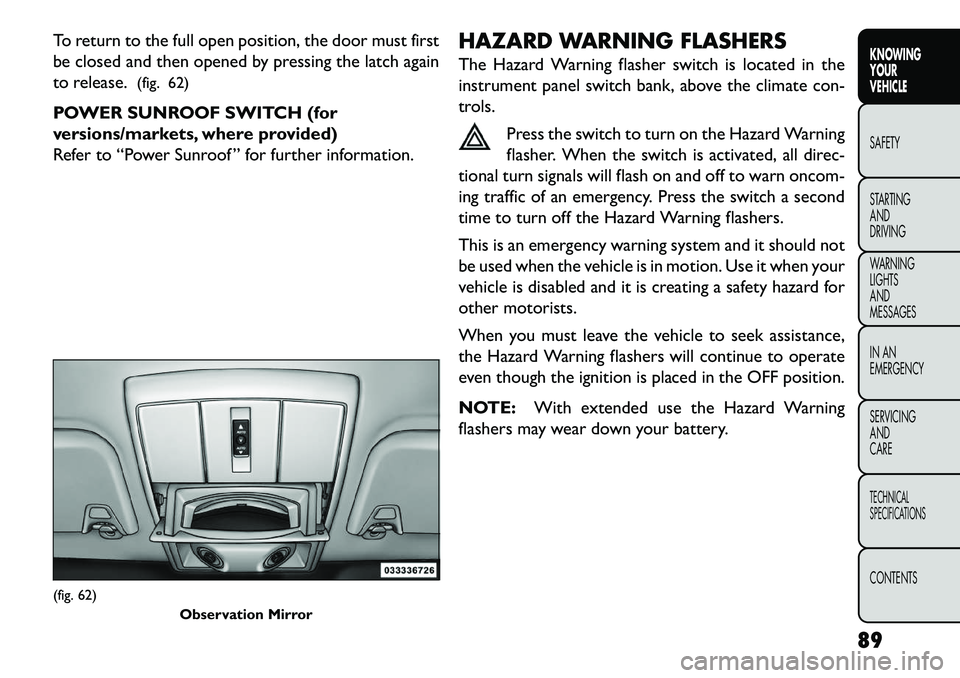
To return to the full open position, the door must first
be closed and then opened by pressing the latch again
to release.(fig. 62)
POWER SUNROOF SWITCH (for
versions/markets, where provided)
Refer to “Power Sunroof ” for further information. HAZARD WARNING FLASHERS
The Hazard Warning flasher switch is located in the
instrument panel switch bank, above the climate con-
trols.
Press the switch to turn on the Hazard Warning
flasher. When the switch is activated, all direc-
tional turn signals will flash on and off to warn oncom-
ing traffic of an emergency. Press the switch a second
time to turn off the Hazard Warning flashers.
This is an emergency warning system and it should not
be used when the vehicle is in motion. Use it when your
vehicle is disabled and it is creating a safety hazard for
other motorists.
When you must leave the vehicle to seek assistance,
the Hazard Warning flashers will continue to operate
even though the ignition is placed in the OFF position.
NOTE: With extended use the Hazard Warning
flashers may wear down your battery.(fig. 62) Observation Mirror
89KNOWING
YOUR
VEHICLE
SAFETY
S
TARTING
AND
DRIVING
WARNING
LIGHTS
AND
MESSAGES
IN AN
EMERGENCY
SERVICING
AND
CARETECHNICAL
SPECIFICATIONSCONTENTS