technical data FIAT FREEMONT 2013 Owner handbook (in English)
[x] Cancel search | Manufacturer: FIAT, Model Year: 2013, Model line: FREEMONT, Model: FIAT FREEMONT 2013Pages: 352, PDF Size: 5.22 MB
Page 1 of 352

OWNER HANDBOOK
FIATFREEMONT
ENGLISH
The data contained in this publication is intended merely as a guide. FIAT reserves the right to modify the models and
versions described in this booklet at any time for technical and commercial reasons.
If you have any further questions please consult your FIAT dealer.
Printed in recycled paper without chlorine.
Page 141 of 352
pressure values. Upon the next ignition switch cycle,
the TPMS will no longer chime or turn on the Tire
Pressure Monitoring Telltale Light, or display the text
message in the EVIC. However, the graphic will still
display “- -.“
To reactivate the TPMS, first, replace all four wheel and
tire assemblies (road tires) with those equipped with
TPM Sensors. Then, drive the vehicle for up to 20
minutes above 25 km/h. The TPMS will chime, the Tire
Pressure Monitoring Telltale Light will flash on and off
for 75 seconds, the EVIC will display a “CHECK TPM
SYSTEM” text message, and the graphic will display tire
pressure values to show that the TPMS is receiving
sensor data.GENERAL INFORMATION
Transmitter and receivers operate on a carrier fre-
quency of 433.92 MHz as required by EEC regulations.
These devices must be certified to conform to specific
regulations in each individual country. Two sets of
regulations are involved: ETS (European Telecommuni-
cation Standard) 300–220, which most countries use,
and German BZT federal regulation 225Z125, which is
based on ETC 300–220 but has additional unique re-
quirements. Other defined requirements are noted in
ANNEX VI of COMMISSION DIRECTIVE 95/56/EC.
Operation is subject to the following two conditions:
This device may not cause harmful interference.
This device must accept any interference received,
including interference that may cause undesired op-
eration.
135
KNOWING
YOUR
VEHICLE
SAFETY
STARTING
AND
DRIVING
WARNING
LIGHTS
AND
MESSAGES
IN AN
EMERGENCY
SERVICING
AND
CARETECHNICAL
SPECIFICATIONSCONTENTS
Page 157 of 352
4. Channel/Screen Selector Switch - Indicates whichchannel is being controlled by the remote control.
When the selector switch is in the Channel 1
position, the remote controls the functionality of
headphone Channel 1 (right side of the screen).
When the selector switch is in the Channel 2,
position the remote controls the functionality of
headphone Channel 2 (left side of the screen).
5. ▸▸ – In radio modes, press to seek the next tunable
station. In disc modes, press and hold to fast for-
ward through the current audio track or video
chapter. In menu modes use to navigate in the menu.
6. ▾/ Prev – In radio modes, press to select to the
previous station. In disc modes, press to advance to
the start of the current or previous audio track or
video chapter. In menu modes, use to navigate in the
menu.
7. MENU – Press to return to the main menu of a DVD disc, to select a satellite audio channel from the
Station list, or select playback modes (RANDOM
for a CD).
8. ▸/||
(Play/Pause) – Begin/resume or pause disc play.
9. ▪(Stop) – Stops disc play
10. PROG Up/Down – When listening to a radio mode, pressing PROG Up selects the next preset
and pressing PROG Down selects the previous preset stored in the radio. When listening to com-
pressed audio on a data disc, PROG Up selects the
next directory and PROG Down selects the pre-
vious directory. When listening to a disc in a radio
with a multiple-disc changer, PROG Up selects the
next disc and PROG Down selects the previous
disc.
11. MUTE – Press to mute the headphone audio out- put for the selected channel.
12. SLOW – Press to slow playback of a DVD disc. Press play (▸) to resume normal play.
13. STATUS – Press to display the current status.
14. MODE – Press to change the mode of the selected channel. See the Mode Selection section of this
manual for details on changing modes.
15. SETUP – When in a video mode, press the SETUP button to access the display settings (see the
display settings section) to access the DVD setup
menu, select the menu button on the radio. When
a disc is loaded in the DVD player (for versions/
markets, where provided) and the VES™ mode is
selected and the disc is stopped, press the SETUP
button to access the DVD Setup menu. (see the
DVD Setup Menu of this manual.)
151
KNOWING
YOUR
VEHICLE
SAFETY
STARTING
AND
DRIVING
WARNING
LIGHTS
AND
MESSAGES
IN AN
EMERGENCY
SERVICING
AND
CARETECHNICAL
SPECIFICATIONSCONTENTS
Page 164 of 352
audio for Channel 1 has been muted using the
remote control’s MUTE button.
3. Channel 2 Audio Only/Mute — Audio: Only in a single screen system: The audio only icon is dis-
played on Channel 2 when Channel 1 is in a video
mode. Mute: when the Mute icon is displayed, the
audio for Channel 2 has been muted using the
remote control’s MUTE button.
4. Channel 2 Mode — Displays the current source for Channel 2.
5. Channel 2 ENTER Button Action — When the ENTER button on the remote control is pressed
with the "INPUT FILE #" button visible on the
screen, the screen shows a numeric entry keypad
which allows you to enter a specific track number
on data discs and HDD (see Numeric Keypad Menu
section of this manual). Also, Enter Button Action –
“INPUT TRK #” to enter a specific track number on
audio discs.
6. Remote Locked Out — When the icon is displayed, the remote control functions are disabled.
7. Clock — Displays the time.
8. Channel 1 Shared Status — When the icon is displayed, the audio for Channel 1 is also shared
with the radio and playing through the cabin speak-
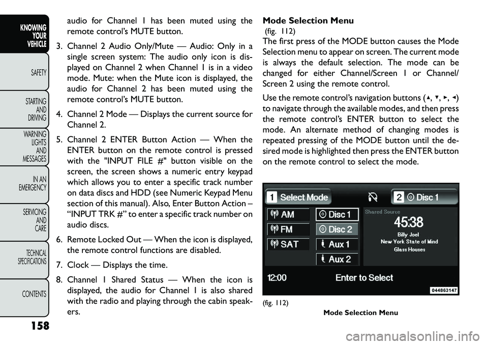
ers. Mode Selection Menu
(fig. 112)
The first press of the MODE button causes the Mode
Selection menu to appear on screen. The current mode
is always the default selection. The mode can be
changed for either Channel/Screen 1 or Channel/
Screen 2 using the remote control.
Use the remote control’s navigation buttons (▴, ▾,▸,◂)
to navigate through the available modes, and then press
the remote control’s ENTER button to select the
mode. An alternate method of changing modes is
repeated pressing of the MODE button until the de-
sired mode is highlighted then press the ENTER button
on the remote control to select the mode.
(fig. 112) Mode Selection Menu
158
KNOWING YOUR
VEHICLE
SAFETY
S
TARTING AND
DRIVING
WARNING LIGHTSAND
MESSAGES
IN AN
EMERGENCY
SERVICING AND
CARETECHNICAL
SPECIFICATIONSCONTENTS
Page 165 of 352
In a single screen system, when a video mode (such as
DVD-video, Aux video, etc.) is active and Channel/
Screen 1 is selected using the remote control selector
switch, the first press of the remote control’s MODE
button causes the Mode Selection menu to appear.
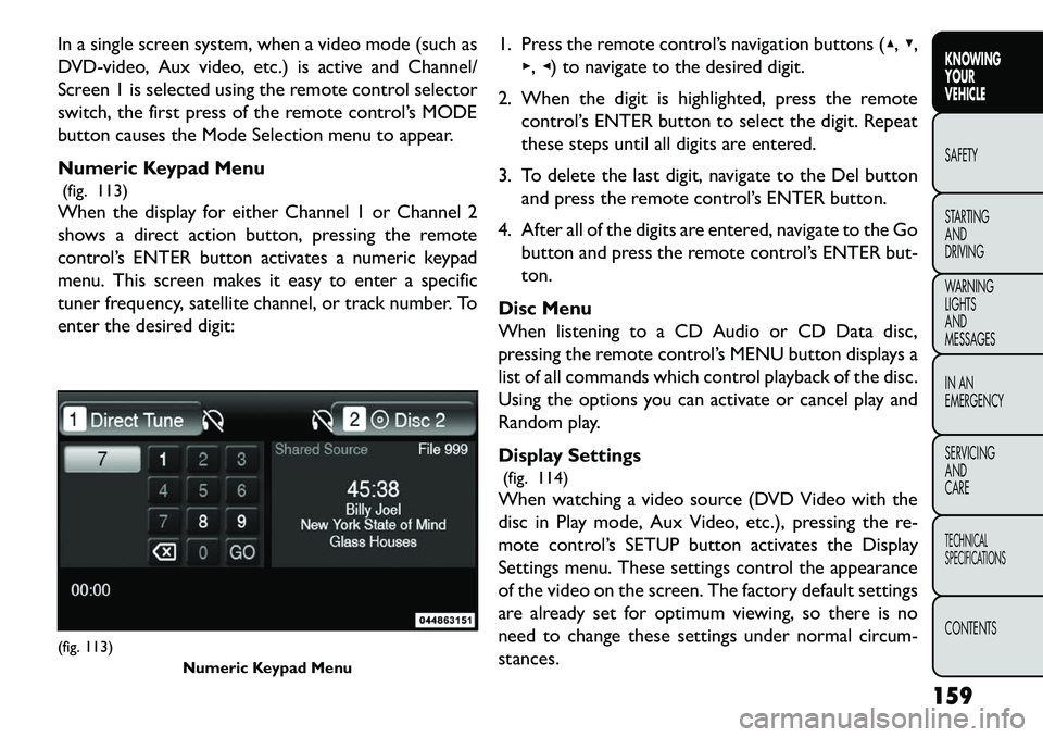
Numeric Keypad Menu(fig. 113)
When the display for either Channel 1 or Channel 2
shows a direct action button, pressing the remote
control’s ENTER button activates a numeric keypad
menu. This screen makes it easy to enter a specific
tuner frequency, satellite channel, or track number. To
enter the desired digit: 1. Press the remote control’s navigation buttons (▴,
▾,
▸, ◂) to navigate to the desired digit.
2. When the digit is highlighted, press the remote control’s ENTER button to select the digit. Repeat
these steps until all digits are entered.
3. To delete the last digit, navigate to the Del button and press the remote control’s ENTER button.
4. After all of the digits are entered, navigate to the Go button and press the remote control’s ENTER but-
ton.
Disc Menu
When listening to a CD Audio or CD Data disc,
pressing the remote control’s MENU button displays a
list of all commands which control playback of the disc.
Using the options you can activate or cancel play and
Random play.
Display Settings (fig. 114)
When watching a video source (DVD Video with the
disc in Play mode, Aux Video, etc.), pressing the re-
mote control’s SETUP button activates the Display
Settings menu. These settings control the appearance
of the video on the screen. The factory default settings
are already set for optimum viewing, so there is no
need to change these settings under normal circum-
stances.(fig. 113) Numeric Keypad Menu
159
KNOWING
YOUR
VEHICLE
SAFETY
S
TARTING
AND
DRIVING
WARNING
LIGHTS
AND
MESSAGES
IN AN
EMERGENCY
SERVICING
AND
CARETECHNICAL
SPECIFICATIONSCONTENTS
Page 203 of 352
EVENT DATA RECORDER (EDR)
This vehicle is equipped with an Event Data Recorder(EDR). The main purpose of an EDR is to record, in
certain crash or near crash-like situations, such as an
air bag deployment or hitting a road obstacle, data
that will assist in understanding how a vehicle’s sys-
tems performed. The EDR is designed to record data
related to vehicle dynamics and safety systems for a
short period of time, typically 30 seconds or less.
The EDR in this vehicle is designed to record such
data as:
How various systems in your vehicle were operating;
Whether or not the driver and passenger safety belts were buckled/fastened;
How far (if at all) the driver was depressing the accelerator and/or brake pedal; and,
How fast the vehicle was traveling.
These data can help provide a better understanding of the circumstances in which crashes and injuries
occur. NOTE:
EDR data are recorded by your vehicle only if
a non-trivial crash situation occurs; no data are re-
corded by the EDR under normal driving conditions
and no personal data (e.g. name, gender, age, and crash
location) are recorded. However, other parties, such as
law enforcement, could combine the EDR data with
the type of personally identifying data routinely ac-
quired during a crash investigation.
To read data recorded by an EDR, special equipment is required, and access to the vehicle or the EDR is
needed. In addition to the vehicle manufacturer,
other parties such as law enforcement, that have the
special equipment, can read the information if they
have access to the vehicle or the EDR.
Transporting Pets
Air Bags deploying in the front seat could harm your
pet. An unrestrained pet will be thrown about and
possibly injured, or injure a passenger during panic
braking or in a collision.
Pets should be restrained in the rear seat in pet har-
nesses or pet carriers that are secured by seat belts.
197
KNOWING
YOUR
VEHICLE
SAFETY
STARTING
AND
DRIVING
WARNING
LIGHTS
AND
MESSAGES
IN AN
EMERGENCY
SERVICING
AND
CARETECHNICAL
SPECIFICATIONSCONTENTS
Page 341 of 352
Daytime Brightness, Interior Lights . . . . . . . . . . . . . . .78
Defroster, Rear Window . . . . . . . . . . . . . . . . . . . . . .84
Defroster, Windshield . . . . . . . . . . . . . . . . . . . .67, 200
Delay (Intermittent) Wipers . . . . . . . . . . . . . . . . . . .80
Diagnostic System, Onboard . . . . . . . . . . . . . . . . . .126
Diesel Fuel . . . . . . . . . . . . . . . . . . . . . . . . . . .327, 328
Diesel Fuel Requirements . . . . . . . . . . . . . . . . . . . .327
Dimmer Switch, Headlight . . . . . . . . . . . . . . . . . . . . .77
DipsticksAutomatic Transmission . . . . . . . . . . . . . . . . . . .309
Oil (Engine) . . . . . . . . . . . . . . . . . . . . . . . .294, 295
Power Steering . . . . . . . . . . . . . . . . . . . . . . . . .128
Disabled Vehicle Towing . . . . . . . . . . . . . . . . . . . . .280
Disposal Antifreeze (Engine Coolant) . . . . . . . . . . . . . . . .306
Door Locks. . . . . . . . . . . . . . . . . . . . . . . . . . . . . .101
Door Locks, Automatic . . . . . . . . . . . . . . . . . . . . . .102
Downshifting . . . . . . . . . . . . . . . . . . . . . . . . . . . . .211
Driving Through Flowing, Rising, or Shallow Standing Water .224
Driving to Achieve Maximum Fuel Economy . . . . . . . . .26
Electrical Outlet, Auxiliary (Power Outlet) . . . . . . . . . .94
Electrical Power Outlets . . . . . . . . . . . . . . . . . . . . . .94
Electric Remote Mirrors . . . . . . . . . . . . . . . . . . . . . .61
Electronic Brake Control System . . . . . . . . . . . . . . .120 Anti-Lock Brake System . . . . . . . . . . . . . . . . . . .119
Brake Assist System . . . . . . . . . . . . . . . . . . . . . .122
Electronic Roll Mitigation . . . . . . . . . . . . . . . . . .122
Electronic Stability Program . . . . . . . . . . . . . . . .123
Traction Control System . . . . . . . . . . . . . . . . . .122
Electronic Roll Mitigation (ERM) . . . . . . . . . . . . . . . .122
Electronic Speed Control (Cruise Control) . . . . . . . . .85 Electronic Stability Program (ESP) . . . . . . . . . . . . . . .123
Electronic Vehicle Information Center (EVIC). . . . .19, 141
Emergency, In Case of
Freeing Vehicle When Stuck . . . . . . . . . . . . . . . .276
Hazard Warning Flasher . . . . . . . . . . . . . . . . . . . .89
Jump Starting . . . . . . . . . . . . . . . . . . . . . . . . . .245
Towing . . . . . . . . . . . . . . . . . . . . . . . . . . . . . .280
Engine. . . . . . . . . . . . . . . . . . . . . . . . . . .202, 291, 293 Air Cleaner . . . . . . . . . . . . . . . . . . . . . . . . . . .296
Break-In Recommendations . . . . . . . . . . . . . . . . .202
Checking Oil Level . . . . . . . . . . . . . . . . . . .294, 295
Compartment . . . . . . . . . . . . . . . . . . . . . .291, 292
Compartment Identification . . . . . . . . . . . . . . . .292
Coolant (Antifreeze) . . . . . . . . . . . . . . . . . .304, 328
Cooling . . . . . . . . . . . . . . . . . . . . . . . . . . . . . .303
Exhaust Gas Caution . . . . . . . . . . . . . . . . . .111, 199
Fails to Start . . . . . . . . . . . . . . . . . . . . . . . . . . .204
Flooded, Starting . . . . . . . . . . . . . . . . . . . . . . . .204
Fuel Requirements . . . . . . . . . . . . . . . . . . . . . . .324
Jump Starting . . . . . . . . . . . . . . . . . . . . . . . . . .245
Oil . . . . . . . . . . . . . . . . . . . . . . . . . .294, 327, 328
Oil Change Interval . . . . . . . . . . . . . . . .25, 295, 296
Oil Filler Cap . . . . . . . . . . . . . . . . . . .291, 293, 296
Oil Selection . . . . . . . . . . . . . . . . . . . . . . . . . .327
Operation . . . . . . . . . . . . . . . . . . . . . . . . . . . .202
Starting . . . . . . . . . . . . . . . . . . . . . . . . . . . . . .202
Temperature Gauge . . . . . . . . . . . . . . . . . . . . . . .7
Engine Oil Viscosity . . . . . . . . . . . . . . . . . . . . .295, 296
Engine Oil Viscosity Chart . . . . . . . . . . . . . . . . . . . .295
Enhanced Accident Response Feature . . . . . . . . . . . .195
Entry System, Illuminated . . . . . . . . . . . . . . . . . . . . .79
Ethanol. . . . . . . . . . . . . . . . . . . . . . . . . . . . . . . . .324
Event Data Recorder . . . . . . . . . . . . . . . . . . . . . . .197
335
KNOWING
YOUR
VEHICLE
SAFETY
STARTING
AND
DRIVING
WARNING
LIGHTS
AND
MESSAGES
IN AN
EMERGENCY
SERVICING
AND
CARETECHNICAL
SPECIFICATIONSCONTENTS
Page 352 of 352
OWNER HANDBOOK
FIATFREEMONT
ENGLISH
The data contained in this publication is intended merely as a guide. FIAT reserves the right to modify the models and
versions described in this booklet at any time for technical and commercial reasons.
If you have any further questions please consult your FIAT dealer.
Printed in recycled paper without chlorine.