manual transmission FIAT FREEMONT 2015 1.G User Guide
[x] Cancel search | Manufacturer: FIAT, Model Year: 2015, Model line: FREEMONT, Model: FIAT FREEMONT 2015 1.GPages: 412, PDF Size: 3.37 MB
Page 260 of 412
AUTOSTICK
AutoStick is a driver-interactive transmission feature
providing manual shift control, giving you more control
of the vehicle. AutoStick allows you to maximize en-
gine braking, eliminate undesirable upshifts and down-
shifts, and improve overall vehicle performance.
This system can also provide you with more control
during passing, city driving, cold slippery conditions,
mountain driving, trailer towing, and many other situ-
ations.
OPERATION
When the shift lever is in the AutoStick position
(below the DRIVE position), it can be moved from side
to side. This allows the driver to manually select the
transmission gear being used. Moving the shift lever to
the left (-) triggers a downshift and to the right (+) an
upshift. The current gear will be displayed in the instru-
ment cluster.In AutoStick mode, the transmission will shift up or
down when the driver moves the shift lever to the right
(+) or left (-), unless an engine lugging or overspeed
condition would result. It will remain in the selected
gear until another upshift or downshift is chosen,
except as described below.
• The transmission will automatically upshift when
necessary to prevent engine over-speed.
• The transmission will automatically downshift as the vehicle slows (to prevent engine lugging) and will
display the current gear.
• The transmission will automatically downshift to first gear when coming to a stop. After a stop, the driver
should manually upshift (+) the transmission as the
vehicle is accelerated.
• You can start out, from a stop, in first or second gear. Tapping (+) (at a stop) will allow starting in second
gear. Starting out in second gear is helpful in snow or
icy conditions.
254
KNOWING YOUR
VEHICLE
SAFETY
STARTING AND
DRIVING
WARNING LIGHTSAND
MESSAGES
INAN
EMERGENC
Y
SERVICING AND CARE
TECHNICAL
SPECIFICATIONS
CONTENTS
Page 268 of 412
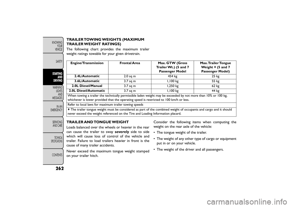
TRAILER TOWING WEIGHTS (MAXIMUM
TRAILER WEIGHT RATINGS)
The following chart provides the maximum trailer
weight ratings towable for your given drivetrain.
Engine/Transmission Frontal AreaMax. GTW (Gross
Trailer Wt.) (5 and 7 Passenger Model Max.Trailer Tongue
Weight ♦(5 and 7
Passenger Model)
2.4L/Automatic 2.0 sq m454 kg25 kg
3.6L/Automatic 3.7 sq m1,100 kg 55 kg
2.0L Diesel/Manual 3.7 sq m1,250 kg 62 kg
2.0L Diesel/Automatic 3.7 sq m1,100 kg 44 kg
When towing a trailer the technically permissible laden weight may be exceeded by not more than 10% or 100 kg,
whichever is lower provided that the operating speed is restricted to 100 km/h or less.
Refer to local laws for maximum trailer towing speeds
♦ The trailer tongue weight must be considered as part of the combined weight of occupants and cargo and it should
never exceed the weight referenced on the Tire and Loading Information placard.
TRAILER AND TONGUE WEIGHT
Loads balanced over the wheels or heavier in the rear
can cause the trailer to sway severelyside to side
which will cause loss of control of the vehicle and
trailer. Failure to load trailers heavier in front is the
cause of many trailer accidents.
Never exceed the maximum tongue weight stamped
on your trailer hitch. Consider the following items when computing the
weight on the rear axle of the vehicle:
• The tongue weight of the trailer.
• The weight of any other type of cargo or equipment
put in or on your vehicle.
• The weight of the driver and all passengers.
262
KNOWING YOUR
VEHICLE
SAFETY
STARTING AND
DRIVING
WARNING LIGHTSAND
MESSAGES
INAN
EMERGENC
Y
SERVICING AND CARE
TECHNICAL
SPECIFICATIONS
CONTENTS
Page 274 of 412
TOWING TIPS
Before setting out on a trip, practice turning, stopping,
and backing up the trailer in an area located away from
heavy traffic.
Manual Transmission (for versions/markets,
where provided)
If using a manual transmission vehicle for trailer towing,
all starts must be in FIRST gear to avoid clutch slippage.
Automatic Transmission (for versions/
markets,where provided)
The DRIVE range can be selected when towing. How-
ever, if frequent shifting occurs while in DRIVE, use the
AutoStick® shift control to manually select a lower
gear.
NOTE:Using a lower gear while operating the vehicle
under heavy loading conditions will improve perfor-
mance and extend transmission life by reducing exces-
sive shifting and heat build up. This action will also
provide better engine braking.
If you REGULARLY tow a trailer for more than 45
minutes of continuous operation, then change the
transmission fluid and filter as specified for “police,
taxi, fleet, or frequent trailer towing.” Refer to the
“Maintenance Schedule” for the proper maintenance
intervals. NOTE:
Check the transmission fluid level (four-speed
transmission only) before towing. The six-speed trans-
mission does not require a fluid level check before
towing. If, however, you notice fluid leakage or trans-
mission malfunction, see your authorized dealer imme-
diately for assistance.
Electronic Speed Control
• Do not use in hilly terrain or with heavy loads.
• When using the speed control, if you experience speed drops greater than 16 km/h, disengage until
you can get back to cruising speed.
• Use speed control in flat terrain and with light loads to maximize fuel efficiency.
AutoStick®
• When using the AutoStick® shift control, select the highest gear that allows for adequate performance
and avoids frequent downshifts. For example, choose
“4” if the desired speed can be maintained. Choose
“3” or “2” if needed to maintain the desired speed.
• To prevent excess heat generation, avoid continuous driving at high RPM. Reduce vehicle speed as neces-
sary to avoid extended driving at high RPM. Return
to a higher gear or vehicle speed when grade and
road conditions allow.
268
KNOWING YOUR
VEHICLE
SAFETY
STARTING AND
DRIVING
WARNING LIGHTSAND
MESSAGES
INAN
EMERGENC
Y
SERVICING AND CARE
TECHNICAL
SPECIFICATIONS
CONTENTS
Page 276 of 412
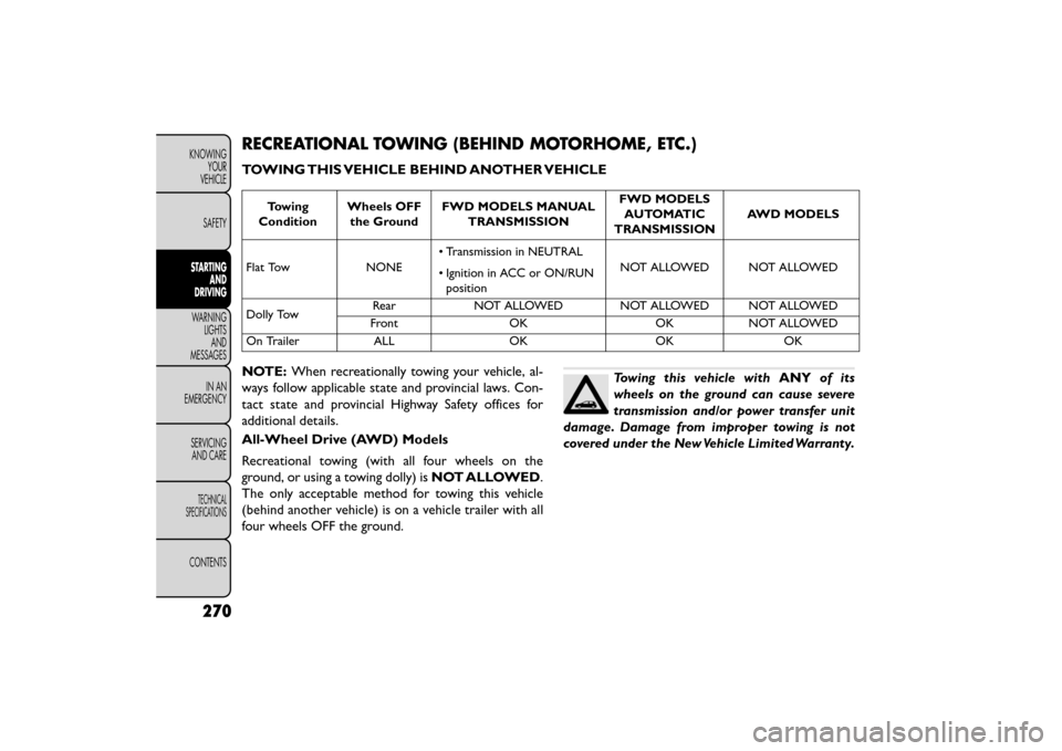
RECREATIONAL TOWING (BEHIND MOTORHOME, ETC.)
TOWING THIS VEHICLE BEHIND ANOTHER VEHICLE
Towing
Condition Wheels OFF
the Ground FWD MODELS MANUAL
TRANSMISSION FWD MODELS
AUTOMATIC
TRANSMISSION AWD MODELS
Flat Tow NONE • Transmission in NEUTRAL
• Ignition in ACC or ON/RUN
position NOT ALLOWED NOT ALLOWED
Dolly Tow Rear NOT ALLOWED NOT ALLOWED NOT ALLOWED
Front OK OK NOT ALLOWED
On Trailer ALL OK OK OK
NOTE: When recreationally towing your vehicle, al-
ways follow applicable state and provincial laws. Con-
tact state and provincial Highway Safety offices for
additional details.
All-Wheel Drive (AWD) Models
Recreational towing (with all four wheels on the
ground, or using a towing dolly) is NOT ALLOWED.
The only acceptable method for towing this vehicle
(behind another vehicle) is on a vehicle trailer with all
four wheels OFF the ground.Towing this vehicle with ANYof its
wheels on the ground can cause severe
transmission and/or power transfer unit
damage. Damage from improper towing is not
covered under the New Vehicle Limited Warranty.
270
KNOWING YOUR
VEHICLE
SAFETY
STARTING AND
DRIVING
WARNING LIGHTSAND
MESSAGES
INAN
EMERGENC
Y
SERVICING AND CARE
TECHNICAL
SPECIFICATIONS
CONTENTS
Page 277 of 412

Front-Wheel Drive (FWD) Models - Manual
Transmission
Front-wheel drive vehicles withmanual transmis-
sions may be flat towed (with all four wheels on the
ground) at any legal highway speed, for any distance, if
the manual transmission is in NEUTRAL and the
ignition is in the ACC or ON/RUN position.
These vehicles may also be towed using a tow dolly
(with the front wheels OFF the ground), or on a flatbed
or vehicle trailer (with all four wheels OFF the ground).
Towing this vehicle in violation of the
above requirements can cause severe en-
gine and/or transmission damage. Dam-
age from improper towing is not covered under
the New Vehicle Limited Warranty. Front-Wheel Drive (FWD) Models - Automatic
Transmission
This vehicle may be towed on a flatbed or vehicle
trailer provided all four wheels are OFF the ground.
This vehicle may also be towed using a tow dolly (with
the front wheels OFF the ground).
•
DO NOT flat tow any vehicle equipped
with an automatic transmission. Damage
to the drivetrain will result . If these ve-
hicles require towing, make sure all drive wheels
are OFF the ground.
• Towing this vehicle in violation of the above
requirements can cause severe transmission dam-
age. Damage from improper towing is not covered
under the New Vehicle Limited Warranty.
271
KNOWING
YOUR
VEHICLE
SAFETY
STARTING
AND
DRIVING
WARNING
LIGHTS
AND
MESSAGES
IN AN
EMERGENC
Y
SERVICING
AND CARE
TECHNICAL
SPECIFICATIONS
CONTENTS
Page 286 of 412
WARNING!
• Take care to avoid the radiator cooling
f an
whenever the hood is raised. It can
start anytime the ignition switch is ON.You can
be injured by moving fan blades.
• Remove any metal jewelry such as rings, watch
bands and bracelets that could make an inadver-
tent electrical contact . You could be seriously
injured.
• Batteries contain sulfuric acid that can burn
your skin or eyes and generate hydrogen gas
which is flammable and explosive. Keep open
flames or sparks away from the battery.
1. Set the parking brake, shift the automatic transmis- sion into PARK and the manual transmission into
gear and turn the ignition to LOCK.
2. Turn off the heater, radio, and all unnecessary elec- trical accessories.
3. Remove the protective cover over the remote posi- tive (+)battery post. To remove the cover, press
the locking tab and pull upward on the cover.
4. If using another vehicle to jump-start the battery, park the vehicle within the jumper cables reach, set
the parking brake and make sure the ignition is OFF.
WARNING!
Do not allow vehicles to touch each
oth er
as this could establish a ground
connection and personal injury could result .
JUMP-STARTING PROCEDURE
WARNING!
Failure to follow this jump-starting pro-
cedure c
ould result in personal injury or
property damage due to battery explosion.
Failure to follow these procedures could
result in damage to the charging system
of the booster vehicle or the discharged
vehicle.
Connecting The Jumper Cables
1. Connect the positive (+)end of the jumper cable to
the remote positive (+)post of the discharged
vehicle.
2. Connect the opposite end of the positive (+)
jumper cable to the positive (+)post of the booster
battery.
3. Connect the negative end (-)of the jumper cable to
the negative (-)post of the booster battery.
280
KNOWING
YOUR
VEHICLE
SAFETY
STARTING AND
DRIVING
WARNING LIGHTSAND
MESSAGES
IN AN
EMERGENCY
SER VICING
AND
CARE
TECHNICAL
SPECIFICATIONS
CONTENTS
Page 290 of 412
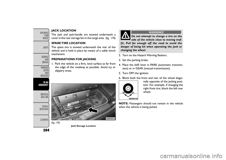
JACK LOCATION
The jack and jack-handle are stowed underneath a
cover in the rear storage bin in the cargo area.
(fig. 170)
SPARE TIRE LOCATION
The spare tire is stowed underneath the rear of the
vehicle and is held in place by means of a cable winch
mechanism.
PREPARATIONS FOR JACKING
1. Park the vehicle on a firm, level surface as far fromthe edge of the roadway as possible. Avoid icy or
slippery areas.
WARNING!
Do not attempt to change a tire on the
side of
the vehicle close to moving traf-
fic . Pull far enough off the road to avoid the
danger of being hit when operating the jack or
changing the wheel.
2. Turn on the Hazard Warning flashers.
3. Set the parking brake.
4. Place the shift lever in PARK (automatic transmis- sion) or in GEAR (manual transmission).
5. Turn OFF the ignition.
6. Block both the front and rear of the wheel diago- nally opposite of the jacking posi-
tion. For example, if changing the
right front tire, block the left rear
wheel.
NOTE: Passengers should not remain in the vehicle
when the vehicle is being jacked.
(fig. 170)
Jack Storage Location
284
KNOWINGYOUR
VEHICLE
SAFETY
STARTING AND
DRIVING
WARNING LIGHTSAND
MESSAGES
IN AN
EMERGENCY
SER VICING
AND
CARE
TECHNICAL
SPECIFICATIONS
CONTENTS
Page 292 of 412
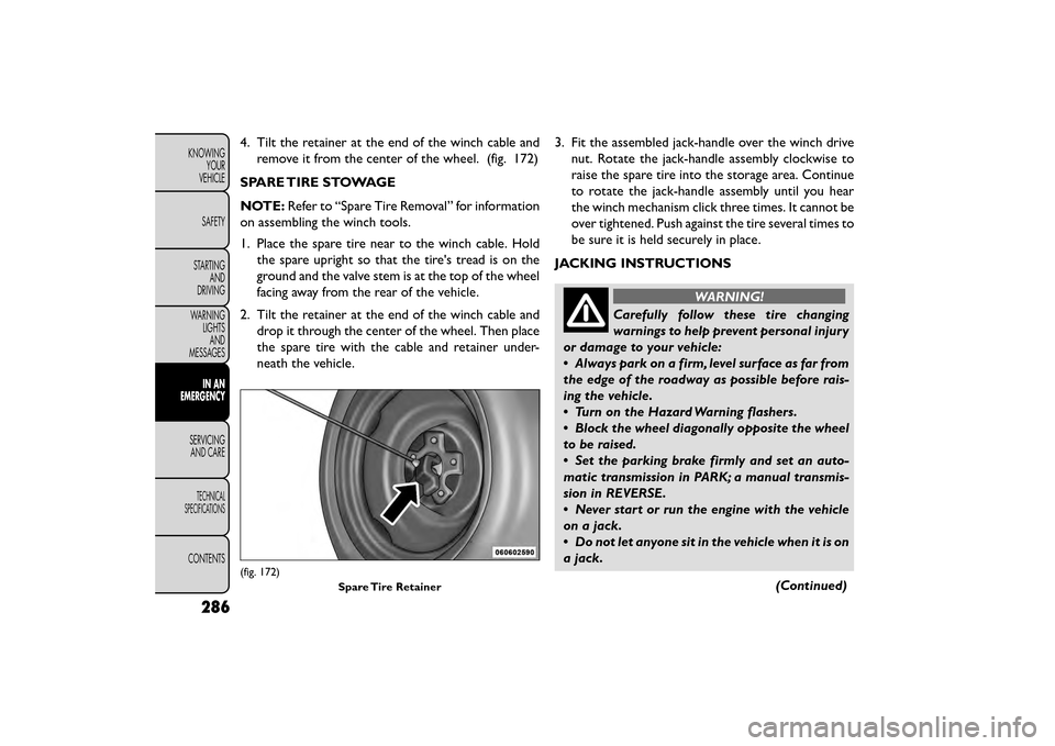
4. Tilt the retainer at the end of the winch cable andremove it from the center of the wheel. (fig. 172)
SPARE TIRE STOWAGE
NOTE: Refer to “Spare Tire Removal” for information
on assembling the winch tools.
1. Place the spare tire near to the winch cable. Hold the spare upright so that the tire's tread is on the
ground and the valve stem is at the top of the wheel
facing away from the rear of the vehicle.
2. Tilt the retainer at the end of the winch cable and drop it through the center of the wheel. Then place
the spare tire with the cable and retainer under-
neath the vehicle. 3. Fit the assembled jack-handle over the winch drive
nut. Rotate the jack-handle assembly clockwise to
raise the spare tire into the storage area. Continue
to rotate the jack-handle assembly until you hear
the winch mechanism click three times. It cannot be
over tightened. Push against the tire several times to
be sure it is held securely in place.
JACKING INSTRUCTIONS
WARNING!
Carefully follow these tire changing
warnin gs
to help prevent personal injury
or damage to your vehicle:
• Always park on a firm, level surface as far from
the edge of the roadway as possible before rais-
ing the vehicle.
• Turn on the Hazard Warning flashers.
• Block the wheel diagonally opposite the wheel
to be raised.
• Set the parking brake firmly and set an auto-
matic transmission in PARK; a manual transmis-
sion in REVERSE.
• Never start or run the engine with the vehicle
on a jack.
• Do not let anyone sit in the vehicle when it is on
a jack.
(Continued)
(fig. 172)Spare Tire Retainer
286
KNOWINGYOUR
VEHICLE
SAFETY
STARTING AND
DRIVING
WARNING LIGHTSAND
MESSAGES
IN AN
EMERGENCY
SER VICING
AND
CARE
TECHNICAL
SPECIFICATIONS
CONTENTS
Page 302 of 412
WARNING! (Continued)
• Take care not to allow the contents of Tire
Service Kit to come in contact with hair, eyes, or
clothing. Tire Service Kit is harmful if inhaled,
swallowed, or absorbed through the skin. It
causes skin, eye, and respiratory irritation. Flush
immediately with plenty of water if there is any
contact with eyes or skin. Change clothing as
soon as possible, if there is any contact with
clothing.
• Tire Service Kit Sealant solution contains latex.
In case of an allergic reaction or rash, consult a
physician immediately. Keep Tire Service Kit out
of reach of children. If swallowed, rinse mouth
immediately with plenty of water and drink
plenty of water. Do not induce vomiting! Consult
a physician immediately.
SEALING A TIRE WITH TIRE SERVICE KIT
(A) Whenever You Stop To Use Tire Service
Kit:
1. Pull over to a safe location and turn on the vehicle’s Hazard Warning flashers.
2. Verify that the valve stem (on the wheel with the deflated tire) is in a position that is near to the
ground. This will allow the Tire Service Kit Hoses (6) and (7) to reach the valve stem and keep the Tire
Service Kit flat on the ground. This will provide the
best positioning of the kit when injecting the sealant
into the deflated tire and running the air pump.
Move the vehicle as necessary to place the valve
stem in this position before proceeding.
3. Place the transmission in PARK (auto transmission) or in Gear (manual transmission) and turn Off the
ignition.
4. Set the parking brake.
(B) Setting Up To Use Tire Service Kit:
1. Push in the Mode Select Knob (5) and turn to the Sealant Mode position.
2. Uncoil the Sealant Hose (6) and then remove the cap from the fitting at the end of the hose.
3. Place the Tire Service Kit flat on the ground next to the deflated tire.
4. Remove the cap from the valve stem and then screw the fitting at the end of the Sealant Hose (6) onto
the valve stem.
5. Uncoil the Power Plug (8) and insert the plug into the vehicle’s 12 Volt power outlet.
296
KNOWING YOUR
VEHICLE
SAFETY
STARTING AND
DRIVING
WARNING LIGHTSAND
MESSAGES
IN AN
EMERGENCY
SER VICING
AND
CARE
TECHNICAL
SPECIFICATIONS
CONTENTS
Page 303 of 412
NOTE:Do not remove foreign objects (e.g., screws or
nails) from the tire.
(C) Injecting Tire Service Kit Sealant Into The
Deflated Tire:
• Always start the engine before turning ON the Tire Service Kit.
NOTE: Manual transmission vehicles must have the
parking brake engaged and the shift lever in NEUTRAL.
• After pressing the Power Button (4), the sealant (white fluid) will flow from the Sealant Bottle (1)
through the Sealant Hose (6) and into the tire.
NOTE: Sealant may leak out through the puncture in
the tire.
If the sealant (white fluid) does not flow within 0
– 10 seconds through the Sealant Hose (6):
1. Press the Power Button (4) to turn Off the Tire Service Kit. Disconnect the Sealant Hose (6) from
the valve stem. Make sure the valve stem is free of
debris. Reconnect the Sealant Hose (6) to the valve
stem. Check that the Mode Select Knob (5) is in the
Sealant Mode position and not Air Mode. Press the
Power Button (4) to turn On the Tire Service Kit. 2. Connect the Power Plug (8) to a different 12 Volt
power outlet in your vehicle or another vehicle, if
available. Make sure the engine is running before
turning ON the Tire Service Kit.
3. The Sealant Bottle (1) may be empty due to previ- ous use. Call for assistance.
NOTE: If the Mode Select Knob (5) is on Air Mode
and the pump is operating, air will dispense from the
Air Pump Hose (7) only, not the Sealant Hose (6).
If the sealant (white fluid) does flow through the
Sealant Hose (6):
1. Continue to operate the pump until sealant is no longer flowing through hose (typically takes 30 - 70
seconds). As the sealant flows through the Sealant
Hose (6), the Pressure Gauge (3) can read as high as
4.8 Bar. The Pressure Gauge (3) will decrease
quickly from approximately 4.8 Bar to the actual tire
pressure when the Sealant Bottle (1) is empty.
2. The pump will start to inject air into the tire immediately after the Sealant Bottle (1) is empty.
Continue to operate the pump and inflate the tire
to the pressure indicated on the tire pressure label
on the driver-side latch pillar (recommended pres-
sure). Check the tire pressure by looking at the
Pressure Gauge (3).
297
KNOWING
YOUR
VEHICLE
SAFETY
STARTING
AND
DRIVING
WARNING
LIGHTS
AND
MESSAGES
IN AN
EMERGENCY
SER VICING
AND
CARE
TECHNICAL
SPECIFICATIONS
CONTENTS