set clock FIAT FREEMONT 2015 1.G User Guide
[x] Cancel search | Manufacturer: FIAT, Model Year: 2015, Model line: FREEMONT, Model: FIAT FREEMONT 2015 1.GPages: 412, PDF Size: 3.37 MB
Page 94 of 412

NOTE:It is not necessary to move the temperature
settings for cold or hot vehicles. The system automati-
cally adjusts the temperature, mode and fan speed to
provide comfort as quickly as possible.
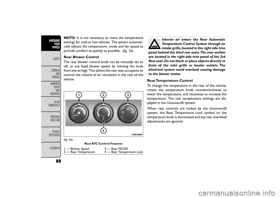
(fig. 56)
Rear Blower Control
The rear blower control knob can be manually set to
off, or any fixed blower speed, by rotating the knob
from low to high. This allows the rear seat occupants to
control the volume of air circulated in the rear of the
vehicle.
Interior air enters the Rear Automatic
Temperature Control System through an
intake grille, located in the right side trim
panel behind the third row seats.The rear outlets
are located in the right side trim panel of the 3rd
Row seat . Do not block or place objects directly in
front of the inlet grille or heater outlets. The
electrical system could overload causing damage
to the blower motor.
Rear Temperature Control
To change the temperature in the rear of the vehicle,
rotate the temperature knob counterclockwise to
lower the temperature, and clockwise to increase the
temperature. The rear temperature settings are dis-
played in the Uconnect® system.
When rear controls are locked by the Uconnect®
system, the Rear Temperature Lock symbol on the
temperature knob is illuminated and any rear overhead
adjustments are ignored.
(fig. 56) Rear ATC Control Features
1 — Blower Speed 3 — Rear MODE
2 — Rear Temperature 4 — Rear Temperature Lock
88
KNOWINGYOUR
VEHICLE
SAFETY
STAR
TINGAND
DRIVING
WARNING LIGHTSAND
MESSAGES
IN AN
EMERGENCY
SERVICINGAND CARE
TECHNICAL
SPECIFICATIONS
CONTENTS
Page 189 of 412

System Information
Information Mode Display
When information mode is active, the current mode
setting for both audio channels is displayed. In addition
to the items called out by number, the remaining
information displays the current status of the source
(such as station frequency, name, preset or track num-
ber, song title, artist name, album name, etc.).
• Channel 1 Mode – Displays the current source forChannel 1.
• Channel 1 Audio Only/Mute — Audio: The audio only icon is not used on Channel 1, in a single screen
system. Mute: when the Mute icon is displayed, the
audio for Channel 1 has been muted using the re-
mote control’s MUTE button.
• Channel 2 Audio Only/Mute — Audio: Only in a single screen system: The audio only icon is displayed
on Channel 2 when Channel 1 is in a video mode.
Mute: when the Mute icon is displayed, the audio for
Channel 2 has been muted using the remote con-
trol’s MUTE button. • Channel 2 Mode — Displays the current source for
Channel 2.
• Channel 2 ENTER Button Action — When the ENTER button on the remote control is pressed
with the "INPUT FILE #" button visible on the
screen, the screen shows a numeric entry keypad
which allows you to enter a specific track number on
data discs and HDD (see Numeric Keypad Menu
section of this manual). Also, Enter Button Action –
“INPUT TRK #” to enter a specific track number on
audio discs.
• Remote Locked Out — When the icon is displayed, the remote control functions are disabled.
• Clock — Displays the time.
• Channel 1 Shared Status — When the icon is dis- played, the audio for Channel 1 is also shared with
the radio and playing through the cabin speakers.
183
KNOWING
YOUR
VEHICLE
SAFETY
STAR
TING
AND
DRIVING
WARNING
LIGHTS
AND
MESSAGES
IN AN
EMERGENCY
SERVICING
AND CARE
TECHNICAL
SPECIFICATIONS
CONTENTS
Page 292 of 412

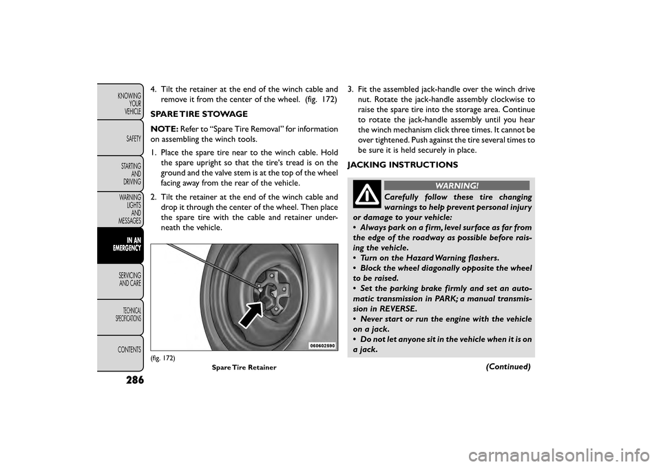
4. Tilt the retainer at the end of the winch cable andremove it from the center of the wheel. (fig. 172)
SPARE TIRE STOWAGE
NOTE: Refer to “Spare Tire Removal” for information
on assembling the winch tools.
1. Place the spare tire near to the winch cable. Hold the spare upright so that the tire's tread is on the
ground and the valve stem is at the top of the wheel
facing away from the rear of the vehicle.
2. Tilt the retainer at the end of the winch cable and drop it through the center of the wheel. Then place
the spare tire with the cable and retainer under-
neath the vehicle. 3. Fit the assembled jack-handle over the winch drive
nut. Rotate the jack-handle assembly clockwise to
raise the spare tire into the storage area. Continue
to rotate the jack-handle assembly until you hear
the winch mechanism click three times. It cannot be
over tightened. Push against the tire several times to
be sure it is held securely in place.
JACKING INSTRUCTIONS
WARNING!
Carefully follow these tire changing
warnin gs
to help prevent personal injury
or damage to your vehicle:
• Always park on a firm, level surface as far from
the edge of the roadway as possible before rais-
ing the vehicle.
• Turn on the Hazard Warning flashers.
• Block the wheel diagonally opposite the wheel
to be raised.
• Set the parking brake firmly and set an auto-
matic transmission in PARK; a manual transmis-
sion in REVERSE.
• Never start or run the engine with the vehicle
on a jack.
• Do not let anyone sit in the vehicle when it is on
a jack.
(Continued)
(fig. 172)Spare Tire Retainer
286
KNOWINGYOUR
VEHICLE
SAFETY
STARTING AND
DRIVING
WARNING LIGHTSAND
MESSAGES
IN AN
EMERGENCY
SER VICING
AND
CARE
TECHNICAL
SPECIFICATIONS
CONTENTS