turn signal FIAT FREEMONT 2015 1.G User Guide
[x] Cancel search | Manufacturer: FIAT, Model Year: 2015, Model line: FREEMONT, Model: FIAT FREEMONT 2015 1.GPages: 412, PDF Size: 3.37 MB
Page 113 of 412
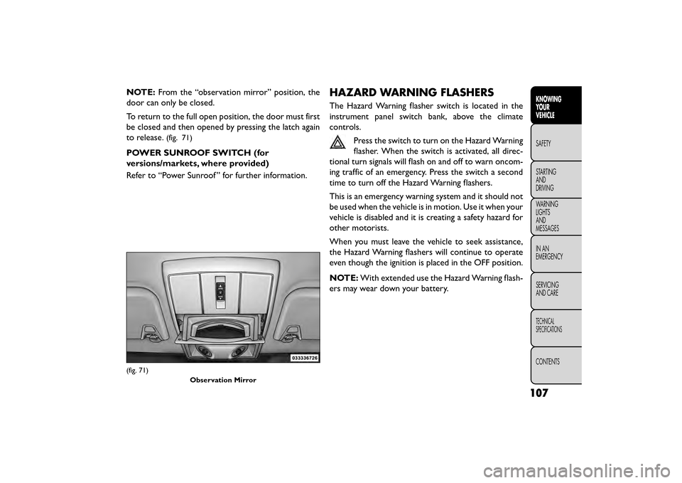
NOTE:From the “observation mirror” position, the
door can only be closed.
To return to the full open position, the door must first
be closed and then opened by pressing the latch again
to release.
(fig. 71)
POWER SUNROOF SWITCH (for
versions/markets, where provided)
Refer to “Power Sunroof ” for further information.
HAZARD WARNING FLASHERS
The Hazard Warning flasher switch is located in the
instrument panel switch bank, above the climate
controls.
Press the switch to turn on the Hazard Warning
flasher. When the switch is activated, all direc-
tional turn signals will flash on and off to warn oncom-
ing traffic of an emergency. Press the switch a second
time to turn off the Hazard Warning flashers.
This is an emergency warning system and it should not
be used when the vehicle is in motion. Use it when your
vehicle is disabled and it is creating a safety hazard for
other motorists.
When you must leave the vehicle to seek assistance,
the Hazard Warning flashers will continue to operate
even though the ignition is placed in the OFF position.
NOTE: With extended use the Hazard Warning flash-
ers may wear down your battery.
(fig. 71)
Observation Mirror
107
KNOWING
YOUR
VEHICLE
SAFETY
STAR
TING
AND
DRIVING
WARNING
LIGHTS
AND
MESSAGES
IN AN
EMERGENCY
SERVICING
AND CARE
TECHNICAL
SPECIFICATIONS
CONTENTS
Page 148 of 412

ABS is activated during braking under certain road or
stopping conditions. ABS-inducing conditions can in-
clude ice, snow, gravel, bumps, railroad tracks, loose
debris, or panic stops.
You also may experience the following when the brake
system goes into Anti-lock:
• The ABS motor running (it may continue to run for ashort time after the stop)
• The clicking sound of solenoid valves
• Brake pedal pulsations
• A slight drop or fall away of the brake pedal at the end of the stop
These are all normal characteristics of ABS.
WARNING!
• The ABS contains sophisticated elec-
t roni
c equipment that may be suscep-
tible to interference caused by improperly in-
stalled or high output radio transmitting
equipment . This interference can cause possible
loss of anti-lock braking capability. Installation
of such equipment should be performed by quali-
fied professionals.
(Continued)
WARNING! (Continued)
• Pumping of the Anti-Lock Brakes will diminish
their effectiveness and may lead to an accident .
Pumping makes the stopping distance longer. Just
press firmly on your brake pedal when you need
toslowdownorstop.
• The ABS cannot prevent the natural laws of
physics from acting on the vehicle, nor can it
increase braking or steering efficiency beyond
that afforded by the condition of the vehicle
brakes and tires or the traction afforded.
• The ABS cannot prevent accidents, including
those resulting from excessive speed in turns,
following another vehicle too closely, or hydro-
planing.
• The capabilities of an ABS equipped vehicle
must never be exploited in a reckless or danger-
ous manner, which could jeopardize the user's
safety or the safety of others.
All vehicle wheels and tires must be the same size and
type and tires must be properly inflated to produce
accurate signals for the computer.
142
KNOWING YOUR
VEHICLE
SAFETY
STAR
TINGAND
DRIVING
WARNING LIGHTSAND
MESSAGES
IN AN
EMERGENCY
SERVICINGAND CARE
TECHNICAL
SPECIFICATIONS
CONTENTS
Page 160 of 412

NOTE:When filling warm tires, the tire pressure may
need to be increased to an additional 0.3 BAR above
the recommended cold placard pressure in order to
turn the Tire Pressure Monitoring Telltale Light off.
Once the system receives the updated tire pressures,
the system will automatically update and the Tire
Pressure Monitoring Telltale Light will turn off. The
vehicle may need to be driven for up to 20 minutes
above 25 km/h in order for the TPMS to receive this
information.
Service TPMS Warning
When a system fault is detected, the Tire Pressure
Monitoring Telltale Light will flash on and off for 75
seconds and then remain on solid. The system fault will
also sound a chime. If the ignition switch is cycled, this
sequence will repeat, providing the system fault still
exists. The Tire Pressure Monitoring Telltale Light will
turn off when the fault condition no longer exists. A
system fault can occur due to any of the following:
1. Jamming due to electronic devices or driving next to facilities emitting the same Radio Frequencies as the
TPMS sensors.
2. Installing some form of aftermarket window tinting that affects radio wave signals. 3. Lots of snow or ice around the wheels or wheel
housings.
4. Using tire chains on the vehicle.
5. Using wheels/tires not equipped with TPMS sen- sors.
NOTE:
1. The compact spare tire does not have a tire pres- sure monitoring sensor. Therefore, the TPMS will
not monitor the pressure in the compact spare tire.
2. If you install the compact spare tire in place of a road tire that has a pressure below the low-pressure
warning limit, a chime will sound and the TPMS
Telltale Light will turn on upon the next ignition
switch cycle.
3. After driving the vehicle for up to 20 minutes above 25 km/h, the TPMS Telltale Light will flash on and off
for 75 seconds and then remain on solid.
4. For each subsequent ignition switch cycle, a chime will sound and the TPMS Telltale Light will flash on
and off for 75 seconds and then remain on solid.
154
KNOWING YOUR
VEHICLE
SAFETY
STAR
TINGAND
DRIVING
WARNING LIGHTSAND
MESSAGES
IN AN
EMERGENCY
SERVICINGAND CARE
TECHNICAL
SPECIFICATIONS
CONTENTS
Page 162 of 412

Tire Pressure Monitoring Low Pressure
WarningsThe Tire Pressure Monitoring Telltale Light will
illuminate in the instrument cluster and a chime
will sound when tire pressure is low in one or more of
the four active road tires. In addition, the Electronic
Vehicle Information Center (EVIC) will display a
graphic showing the pressure values of each tire with
the low tire pressure values in a different color. An
"Inflate Tire to XXX" message will also be displayed.
Should this occur, you should stop as soon as possible
and inflate the tires with low pressure (those displayed
in a different color in the EVIC graphic) to the vehicle’s
recommended cold placard pressure value as shown in
the "Inflate Tire to XXX" message.
NOTE: When filling warm tires, the tire pressure may
need to be increased to an additional 0.3 BAR above
the recommended cold placard pressure in order to
turn the Tire Pressure Monitoring Telltale Light off.
Once the system receives the updated tire pressures,
the system will automatically update, the graphic dis-
play in the EVIC will return to the original color, and
the Tire Pressure Monitoring Telltale Light will turn off.
The vehicle may need to be driven for up to 20 minutes
above 25 km/h in order for the TPMS to receive this
information. ServiceTPMS Warning
When a system fault is detected, the Tire Pressure
Monitoring Telltale Light will flash on and off for 75
seconds and then remain on solid. The system fault will
also sound a chime. In addition, the EVIC will display a
"SERVICE TPM SYSTEM" message for a minimum of
five seconds and then display dashes (- -) in place of the
pressure value to indicate which sensor is not being
received.
If the ignition switch is cycled, this sequence will repeat,
providing the system fault still exists. If the system fault
no longer exists, the Tire Pressure Monitoring Telltale
Light will no longer flash, and the "SERVICE TPM
SYSTEM" message will no longer display, and a pressure
value will display in place of the dashes. A system fault
can occur due to any of the following:
1. Jamming due to electronic devices or driving next to
facilities emitting the same radio frequencies as the
TPMS sensors.
2. Installing some form of aftermarket window tinting that affects radio wave signals.
3. Lots of snow or ice around the wheels or wheel housings.
4. Using tire chains on the vehicle.
5.
Using wheels/tires not equipped with TPMS sensors.
156
KNOWING YOUR
VEHICLE
SAFETY
STAR
TINGAND
DRIVING
WARNING LIGHTSAND
MESSAGES
IN AN
EMERGENCY
SERVICINGAND CARE
TECHNICAL
SPECIFICATIONS
CONTENTS
Page 242 of 412
WARNING! (Continued)
• If required, mounting posts must be properly
installed, if not equipped from the factory. Fail-
ure to properly follow floor mat installation or
mounting can cause interference with the brake
pedal and accelerator pedal operation causing
loss of control of the vehicle.
Periodic Safety Checks You Should Make
Outside The Vehicle
Tires
Examine tires for excessive tread wear and uneven
wear patterns. Check for stones, nails, glass, or other
objects lodged in the tread or sidewall. Inspect the
tread for cuts and cracks. Inspect sidewalls for cuts,
cracks and bulges. Check the wheel nuts for tightness.
Check the tires (including spare) for proper cold infla-
tion pressure. Lights
Have someone observe the operation of brake lights
and exterior lights while you work the controls. Check
turn signal and high beam indicator lights on the instru-
ment panel.
Door Latches
Check for positive closing, latching, and locking.
Fluid Leaks
Check area under vehicle after overnight parking for
fuel, engine coolant, oil, or other fluid leaks. Also, if
gasoline fumes are detected or if fuel, power steering
fluid (for versions/markets, where provided), or brake
fluid leaks are suspected, the cause should be located
and corrected immediately.
236
KNOWING
YOUR
VEHICLE
SAFETY
STARTING AND
DRIVING
WARNING LIGHTSAND
MESSAGES
IN
AN
EMERGENCY
SERVICINGAND CARE
TECHNICAL
SPECIFICATIONS
CONTENTS
Page 271 of 412
WARNING!
• Do not connect trailer brakes to your
v ehi
cle's hydraulic brake lines. It can
overload your brake system and cause it to fail.
You might not have brakes when you need them
and could have an accident .
• Towing any trailer will increase your stopping
distance. When towing, you should allow for ad-
ditional space between your vehicle and the ve-
hicle in front of you. Failure to do so could result
in an accident .
Towing Requirements — Trailer Lights And
Wiring
Whenever you pull a trailer, regardless of the trailer
size, stoplights and turn signals on the trailer are
required for motoring safety.
The Trailer Tow Package may include a seven-pin or a
thirteen-pin wiring harness. Use a factory approved
trailer harness and connector. NOTE:
Do not cut or splice wiring into the vehicles
wiring harness.
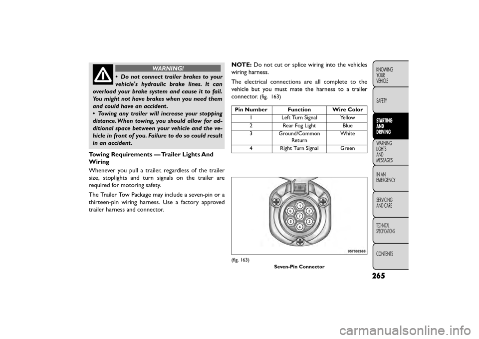
The electrical connections are all complete to the
vehicle but you must mate the harness to a trailer
connector.
(fig. 163)
Pin Number Function Wire Color
1 Left Turn Signal Yellow
2 Rear Fog Light Blue
3 Ground/Common Return White
4 Right Turn Signal Green
(fig. 163) Seven-Pin Connector
265
KNOWING
YOUR
VEHICLE
SAFETY
STARTING
AND
DRIVING
WARNING
LIGHTS
AND
MESSAGES
INAN
EMERGENC
Y
SERVICING
AND CARE
TECHNICAL
SPECIFICATIONS
CONTENTS
Page 272 of 412
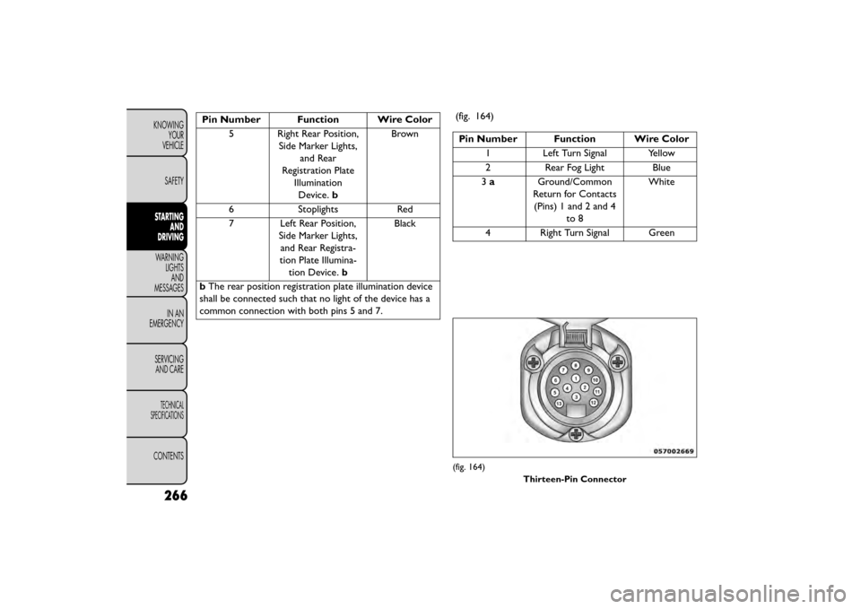
Pin Number Function Wire Color5 Right Rear Position, Side Marker Lights,and Rear
Registration Plate IlluminationDevice. b Brown
6 Stoplights Red
7 Left Rear Position, Side Marker Lights,and Rear Registra-
tion Plate Illumina- tion Device. bBlack
b The rear position registration plate illumination device
shall be connected such that no light of the device has a
common connection with both pins 5 and 7. (fig. 164)
Pin Number Function Wire Color
1 Left Turn Signal Yellow
2 Rear Fog Light Blue
3 a Ground/Common
Return for Contacts (Pins) 1 and 2 and 4 to 8 White
4 Right Turn Signal Green
(fig. 164) Thirteen-Pin Connector
266
KNOWINGYOUR
VEHICLE
SAFETY
STARTING AND
DRIVING
WARNING LIGHTSAND
MESSAGES
INAN
EMERGENC
Y
SERVICING AND CARE
TECHNICAL
SPECIFICATIONS
CONTENTS
Page 280 of 412
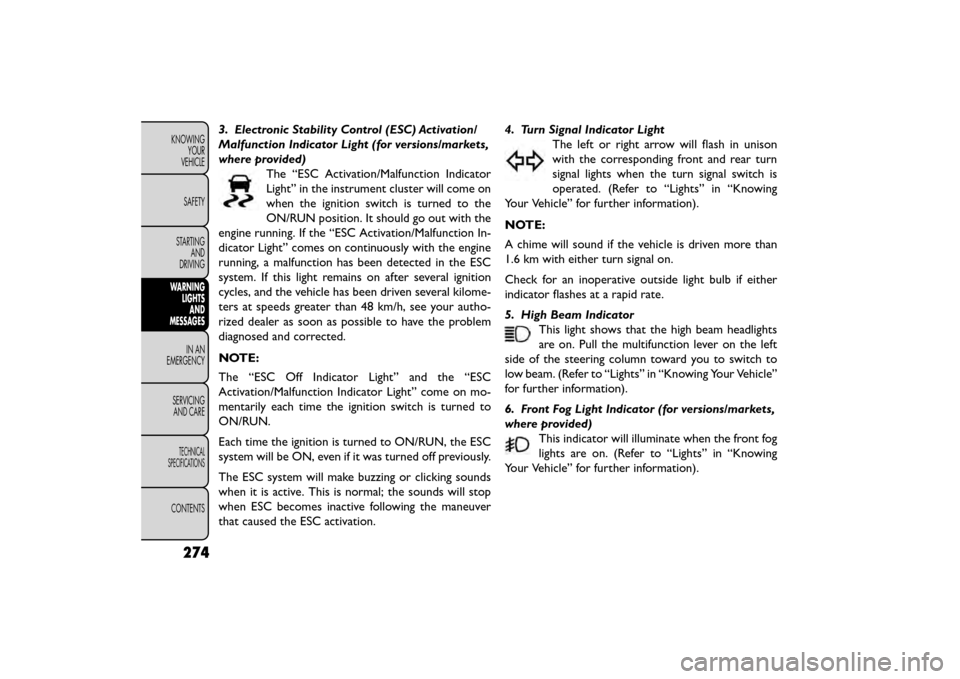
3. Electronic Stability Control (ESC) Activation/
Malfunction Indicator Light (for versions/markets,
where provided)The “ESC Activation/Malfunction Indicator
Light” in the instrument cluster will come on
when the ignition switch is turned to the
ON/RUN position. It should go out with the
engine running. If the “ESC Activation/Malfunction In-
dicator Light” comes on continuously with the engine
running, a malfunction has been detected in the ESC
system. If this light remains on after several ignition
cycles, and the vehicle has been driven several kilome-
ters at speeds greater than 48 km/h, see your autho-
rized dealer as soon as possible to have the problem
diagnosed and corrected.
NOTE:
The “ESC Off Indicator Light” and the “ESC
Activation/Malfunction Indicator Light” come on mo-
mentarily each time the ignition switch is turned to
ON/RUN.
Each time the ignition is turned to ON/RUN, the ESC
system will be ON, even if it was turned off previously.
The ESC system will make buzzing or clicking sounds
when it is active. This is normal; the sounds will stop
when ESC becomes inactive following the maneuver
that caused the ESC activation. 4. Turn Signal Indicator Light
The left or right arrow will flash in unison
with the corresponding front and rear turn
signal lights when the turn signal switch is
operated. (Refer to “Lights” in “Knowing
Your Vehicle” for further information).
NOTE:
A chime will sound if the vehicle is driven more than
1.6 km with either turn signal on.
Check for an inoperative outside light bulb if either
indicator flashes at a rapid rate.
5. High Beam Indicator This light shows that the high beam headlights
are on. Pull the multifunction lever on the left
side of the steering column toward you to switch to
low beam. (Refer to “Lights” in “Knowing Your Vehicle”
for further information).
6. Front Fog Light Indicator (for versions/markets,
where provided) This indicator will illuminate when the front fog
lights are on. (Refer to “Lights” in “Knowing
Your Vehicle” for further information).
274
KNOWING YOUR
VEHICLE
SAFETY
STARTING AND
DRIVING
WARNING LIGHTSAND
MESSAGES
INAN
EMERGENC
Y
SERVICING AND
CARE
TECHNICAL
SPECIFICATIONS
CONTENTS
Page 282 of 412
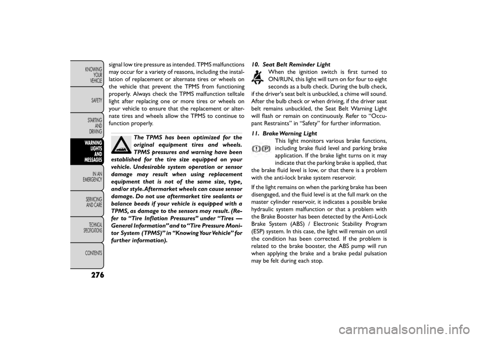
signal low tire pressure as intended. TPMS malfunctions
may occur for a variety of reasons, including the instal-
lation of replacement or alternate tires or wheels on
the vehicle that prevent the TPMS from functioning
properly. Always check the TPMS malfunction telltale
light after replacing one or more tires or wheels on
your vehicle to ensure that the replacement or alter-
nate tires and wheels allow the TPMS to continue to
function properly.
The TPMS has been optimized for the
original equipment tires and wheels.
TPMS pressures and warning have been
established for the tire size equipped on your
vehicle. Undesirable system operation or sensor
damage may result when using replacement
equipment that is not of the same size, type,
and/or style.Aftermarket wheels can cause sensor
damage. Do not use aftermarket tire sealants or
balance beads if your vehicle is equipped with a
TPMS, as damage to the sensors may result . (Re-
fer to “Tire Inflation Pressures” under “Tires —
General Information” and to “Tire Pressure Moni-
tor System (TPMS)” in “Knowing Your Vehicle” for
further information). 10. Seat Belt Reminder Light
When the ignition switch is first turned to
ON/RUN, this light will turn on for four to eight
seconds as a bulb check. During the bulb check,
if the driver's seat belt is unbuckled, a chime will sound.
After the bulb check or when driving, if the driver seat
belt remains unbuckled, the Seat Belt Warning Light
will flash or remain on continuously. Refer to “Occu-
pant Restraints” in “Safety” for further information.
11. Brake Warning Light This light monitors various brake functions,
including brake fluid level and parking brake
application. If the brake light turns on it may
indicate that the parking brake is applied, that
the brake fluid level is low, or that there is a problem
with the anti-lock brake system reservoir.
If the light remains on when the parking brake has been
disengaged, and the fluid level is at the full mark on the
master cylinder reservoir, it indicates a possible brake
hydraulic system malfunction or that a problem with
the Brake Booster has been detected by the Anti-Lock
Brake System (ABS) / Electronic Stability Program
(ESP) system. In this case, the light will remain on until
the condition has been corrected. If the problem is
related to the brake booster, the ABS pump will run
when applying the brake and a brake pedal pulsation
may be felt during each stop.
276
KNOWING YOUR
VEHICLE
SAFETY
STARTING AND
DRIVING
WARNING LIGHTSAND
MESSAGES
INAN
EMERGENC
Y
SERVICING AND
CARE
TECHNICAL
SPECIFICATIONS
CONTENTS
Page 307 of 412
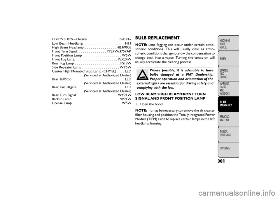
LIGHTS BULBS – OutsideBulb No.
Low Beam Headlamp....................H11
High Beam Headlamp ................HB3/9005
Front Turn Signal ..............PY27W/3757AK
Front Position Lamp ...................W5W
Front Fog Lamp ..................... PSX24W
Rear Fog Lamp ....................... PS19W
Side Repeater Lamp ................... WY5W
Center High Mounted Stop Lamp (CHMSL)....LED (Serviced at Authorized Dealer)
Rear Tail/Stop..........................LED(Serviced at Authorized Dealer)
RearTailLiftgate........................LED (Serviced at Authorized Dealer)
Rear Turn Signal ..................... WY21W
Backup Lamp ........................ W21W
License Lamp .........................W5W
BULB REPLACEMENT
NOTE:Lens fogging can occur under certain atmo-
spheric conditions. This will usually clear as atmo-
spheric conditions change to allow the condensation to
change back into a vapor. Turning the lamps on will
usually accelerate the clearing process.
Where possible, it is advisable to have
bulbs changed at a FIAT Dealership.
Proper operation and orientation of the
external lights are essential for driving safety and
complying with the law.
LOW BEAM/HIGH BEAM/FRONT TURN
SIGNAL AND FRONT POSITION LAMP
1. Open the hood.
NOTE: It may be necessary to remove the air cleaner
filter housing and position the Totally Integrated Power
Module (TIPM) aside to replace certain lamps in the left
headlamp housing.
301
KNOWING
YOUR
VEHICLE
SAFETY
STARTING
AND
DRIVING
WARNING
LIGHTS
AND
MESSAGES
IN AN
EMERGENCY
SER VICING
AND
CARE
TECHNICAL
SPECIFICATIONS
CONTENTS