213 FIAT FULLBACK 2016 1.G Owners Manual
[x] Cancel search | Manufacturer: FIAT, Model Year: 2016, Model line: FULLBACK, Model: FIAT FULLBACK 2016 1.GPages: 312, PDF Size: 13.67 MB
Page 11 of 312

GRAPHICAL INDEX
HEADLIGHTSBulb types..................... 213Daytime running lights........... 40Dipper beam headlights......... 40Headlamps..................... 40Bulb replacement.............. 213
WHEELSTyres and wheels.............. 291Tyre pressure.................. 291Replacing a wheel............. 194
OUTSIDE REARVIEW MIRRORSAdjustment..................... 37
DOORSCentral opening/closing......... 28
WINDSCREEN WIPERSOperation....................... 48Blade replacement............. 254
ENGINEChecking levels................ 241Engine specifications.......... 268
3
2
1
1
5
6
4
1FRONTE
9
Page 12 of 312
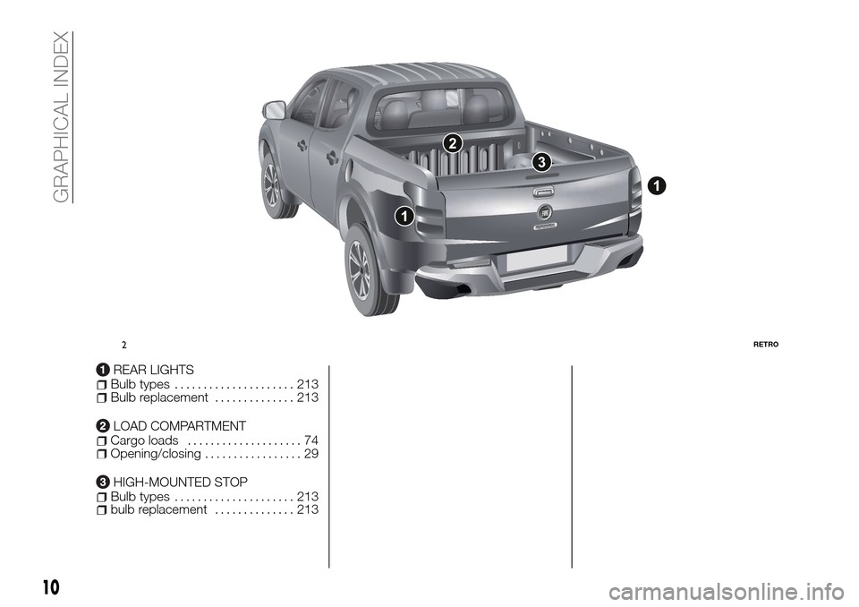
REAR LIGHTSBulb types..................... 213Bulb replacement.............. 213
LOAD COMPARTMENTCargo loads.................... 74Opening/closing................. 29
HIGH-MOUNTED STOPBulb types..................... 213bulb replacement.............. 213
2
3
1
1
2RETRO
10
GRAPHICAL INDEX
Page 16 of 312

Vehicles without keyless operation
system
In the following cases, the vehicle may
not be able to receive the registered ID
code from the registered key and
engine may not start.
When the key contacts a key ring or
other metallic or magnetic object
When the key grip contacts metal of
another key
When the key contacts or is close to
other immobilizing keys (including keys
of other vehicles) In cases like these,
remove the object or additional key
from the vehicle key. Then try again to
start the engine. If the engine does not
start, we recommend you to contact a
Fiat Dealership.
NOTE If you lose one of the master
keys, the keyless entry keys or the
keyless operation keys, contact a Fiat
Dealership as soon as possible. Refer
to “Keys”. To obtain a key, take your
vehicle and all remaining keys to a Fiat
Dealership. If you need an extra spare
key, take your vehicle and all the keys
to a Fiat Dealership. All the keys have to
be re-registered in the immobilizer
computer unit. For further information,
please contact a Fiat Dealership.
KEYLESS ENTRY SYSTEM
Press the key switch to lock or unlock
the doors. It is also possible to operate
the outside rearview mirrors. (Vehicles
equipped with the mirror retractor
switch).
1. LOCK switch 2. UNLOCK switch
3. Indicator lamp
To lock
Press the LOCK switch (1). All the
doors will be locked. The turn-signal
lamps will blink once. When they are
locked with the room lamp switch in the
middle (●) position, the room lamp also
blink once.
To unlock
Press the UNLOCK switch (2). All the
doors will be unlocked. If the room
lamp switch is in the middle (●) position
at this time, the room lamp will come on
for approximately 15 seconds and theturn-signal lamps will blink twice.
NOTE For vehicles equipped with the
mirror retractor switch, the outside
rear-view mirrors automatically retract
or extend when all the doors are locked
or unlocked using the key switches of
the keyless entry system. Refer to
“Starting and driving: Outside rear-view
mirrors”.
NOTE If the UNLOCK switch (2) is
pressed and no door is opened within
approximately 30 seconds, relocking
will automatically occur.
It is possible to modify functions as
follows: For further information, please
contact a Fiat Dealership.
The time from pressing of the
UNLOCK switch (2) to the moment of
automatic locking can be changed.
Activating the operation confirmation
function (blinking of the turn-signal
lamps) only during locking, or only
during unlocking.
The confirmation function (this
indicates locking or unlocking of the
doors with the blink of the turn-signal
lamps) can be deactivated.
The number of times the turn-signal
lamps are blinked by the confirmation
function can be changed.
On vehicles with keyless operation
system, the buzzer sound can be
activated when a keyless operation is
done.
13
2213
6AHA101774
14
GETTING TO KNOW YOUR VEHICLE
Page 61 of 312
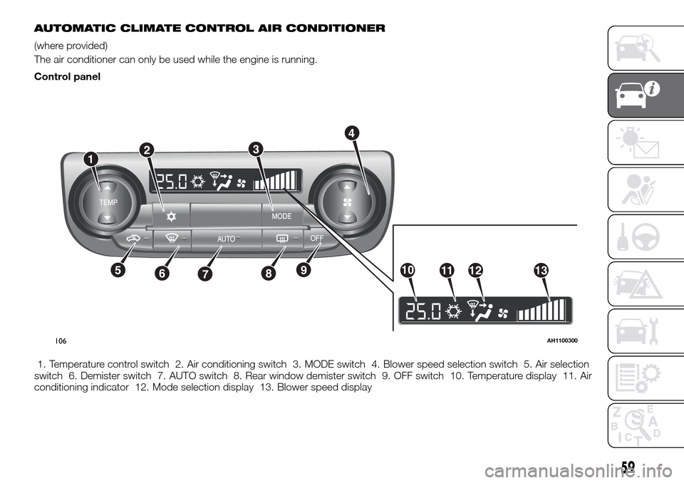
AUTOMATIC CLIMATE CONTROL AIR CONDITIONER
(where provided)
The air conditioner can only be used while the engine is running.
Control panel
1. Temperature control switch 2. Air conditioning switch 3. MODE switch 4. Blower speed selection switch 5. Air selection
switch 6. Demister switch 7. AUTO switch 8. Rear window demister switch 9. OFF switch 10. Temperature display 11. Air
conditioning indicator 12. Mode selection display 13. Blower speed display
1
1011121356789
3
4
2
106AH1100300
59
Page 124 of 312
Side airbag system
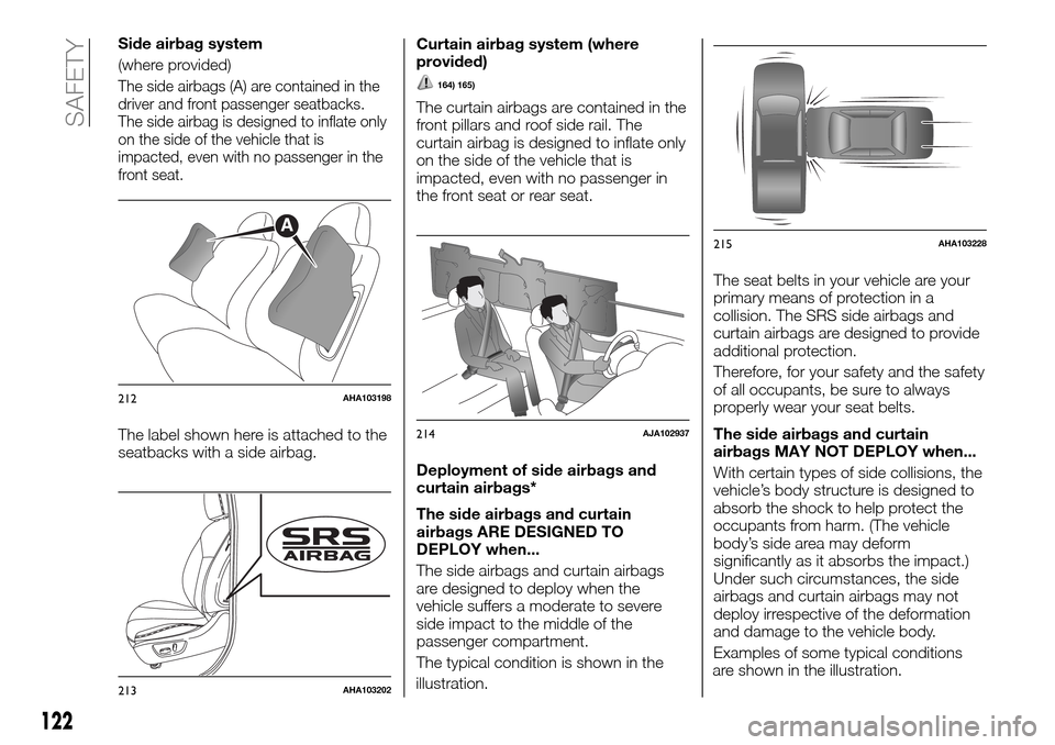
(where provided)
The side airbags (A) are contained in the
driver and front passenger seatbacks.
The side airbag is designed to inflate only
on the side of the vehicle that is
impacted, even with no passenger in the
front seat.
The label shown here is attached to the
seatbacks with a side airbag.Curtain airbag system (where
provided)
164) 165)
The curtain airbags are contained in the
front pillars and roof side rail. The
curtain airbag is designed to inflate only
on the side of the vehicle that is
impacted, even with no passenger in
the front seat or rear seat.
Deployment of side airbags and
curtain airbags*
The side airbags and curtain
airbags ARE DESIGNED TO
DEPLOY when...
The side airbags and curtain airbags
are designed to deploy when the
vehicle suffers a moderate to severe
side impact to the middle of the
passenger compartment.
The typical condition is shown in the
illustration.The seat belts in your vehicle are your
primary means of protection in a
collision. The SRS side airbags and
curtain airbags are designed to provide
additional protection.
Therefore, for your safety and the safety
of all occupants, be sure to always
properly wear your seat belts.
The side airbags and curtain
airbags MAY NOT DEPLOY when...
With certain types of side collisions, the
vehicle’s body structure is designed to
absorb the shock to help protect the
occupants from harm. (The vehicle
body’s side area may deform
significantly as it absorbs the impact.)
Under such circumstances, the side
airbags and curtain airbags may not
deploy irrespective of the deformation
and damage to the vehicle body.
Examples of some typical conditions
A
212AHA103198
213AHA103202
214AJA102937
215AHA103228
122
SAFETY
are shown in the illustration.
Page 167 of 312
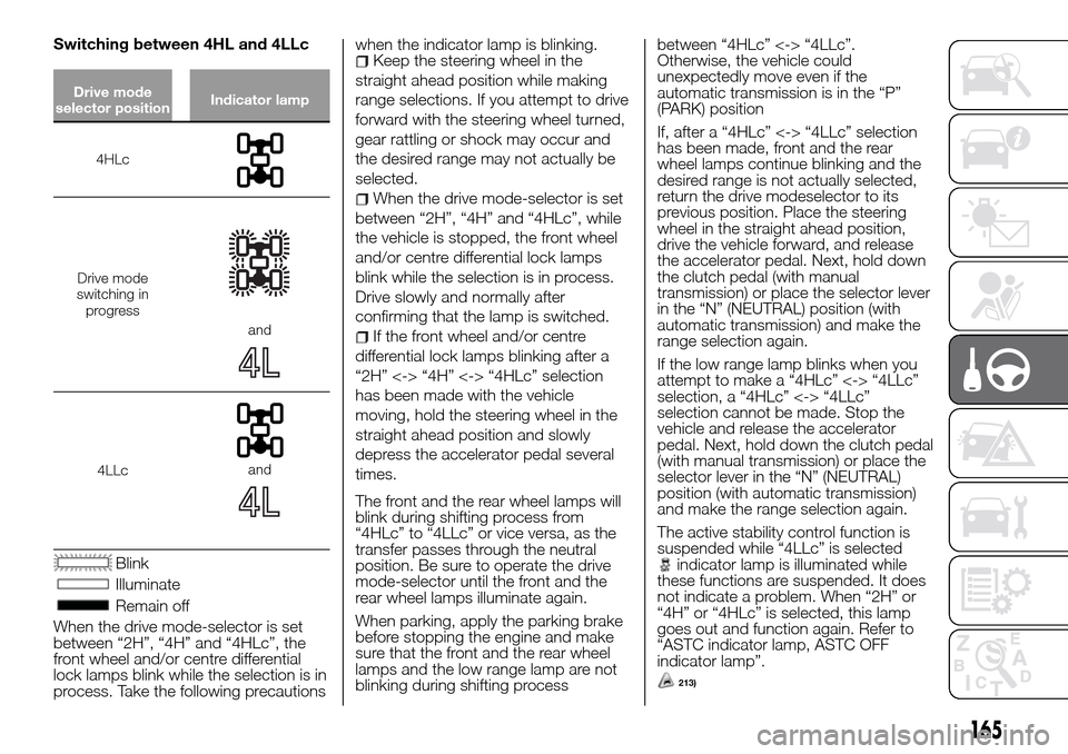
Switching between 4HL and 4LLc
Drive mode
selector positionIndicator lamp
4HLc
Drive mode
switching in
progress
and
4LLcand
Blink
Illuminate
Remain off
When the drive mode-selector is set
between “2H”, “4H” and “4HLc”, the
front wheel and/or centre differential
lock lamps blink while the selection is in
process. Take the following precautionswhen the indicator lamp is blinking.
Keep the steering wheel in the
straight ahead position while making
range selections. If you attempt to drive
forward with the steering wheel turned,
gear rattling or shock may occur and
the desired range may not actually be
selected.
When the drive mode-selector is set
between “2H”, “4H” and “4HLc”, while
the vehicle is stopped, the front wheel
and/or centre differential lock lamps
blink while the selection is in process.
Drive slowly and normally after
confirming that the lamp is switched.
If the front wheel and/or centre
differential lock lamps blinking after a
“2H” <-> “4H” <-> “4HLc” selection
has been made with the vehicle
moving, hold the steering wheel in the
straight ahead position and slowly
depress the accelerator pedal several
times.
The front and the rear wheel lamps will
blink during shifting process from
“4HLc” to “4LLc” or vice versa, as the
transfer passes through the neutral
position. Be sure to operate the drive
mode-selector until the front and the
rear wheel lamps illuminate again.
When parking, apply the parking brake
before stopping the engine and make
sure that the front and the rear wheel
lamps and the low range lamp are not
blinking during shifting processbetween “4HLc” <-> “4LLc”.
Otherwise, the vehicle could
unexpectedly move even if the
automatic transmission is in the “P”
(PARK) position
If, after a “4HLc” <-> “4LLc” selection
has been made, front and the rear
wheel lamps continue blinking and the
desired range is not actually selected,
return the drive modeselector to its
previous position. Place the steering
wheel in the straight ahead position,
drive the vehicle forward, and release
the accelerator pedal. Next, hold down
the clutch pedal (with manual
transmission) or place the selector lever
in the “N” (NEUTRAL) position (with
automatic transmission) and make the
range selection again.
If the low range lamp blinks when you
attempt to make a “4HLc” <-> “4LLc”
selection, a “4HLc” <-> “4LLc”
selection cannot be made. Stop the
vehicle and release the accelerator
pedal. Next, hold down the clutch pedal
(with manual transmission) or place the
selector lever in the “N” (NEUTRAL)
position (with automatic transmission)
and make the range selection again.
The active stability control function is
suspended while “4LLc” is selected
indicator lamp is illuminated while
these functions are suspended. It does
not indicate a problem. When “2H” or
“4H” or “4HLc” is selected, this lamp
goes out and function again. Refer to
“ASTC indicator lamp, ASTC OFF
indicator lamp”.
213)
165
Page 168 of 312
WARNING
210)The “4LLc” range gives maximum
torque for low-speed driving on steep
slopes, as well as sandy, muddy, and other
difficult surfaces. On vehicles with
automatic transmission, do not exceed
speeds of approximately 70 km/h in “4LLc”
range.
211)Do not drive your vehicle in the
“4HLc” or “4LLc” position on dry paved
roads and highways. Doing so may result
in excessive tyre wear, increased fuel
consumption, and possible noise
generation. It may also increase the
differential oil temperature, which may
damage the drive system. Further, the drive
train will be subjected to excessive loading,
resulting in oil leakage, component seizure,
or other serious problems. On dry paved
roads and highways, drive the vehicle in
“2H” or “4H” only.212)Do not operate the drive
mode-selector while the rear wheels of the
vehicle are slipping on snow or ice.
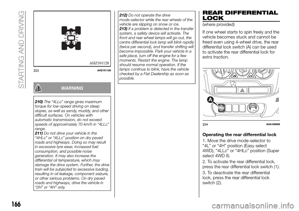
213)If a problem is detected in the transfer
system, a safety device will activate. The
front and rear wheel lamps will go out, the
centre differential lock lamp will blink rapidly
(twice per second), and transfer shifting will
become impossible. Park your vehicle in a
safe place, turn off the engine for a few
moments. Restart the engine. The lamp
should resume normal operation. If the
lamps continue to blink, have the vehicle
checked by a Fiat Dealership as soon as
possible.
REAR DIFFERENTIAL
LOCK
(where provided)
If one wheel starts to spin freely and the
vehicle becomes stuck and cannot be
freed even using 4-wheel drive, the rear
differential lock switch (A) can be used
to activate the rear differential lock for
extra traction.
Operating the rear differential lock
1. Move the drive mode-selector to
“4L” or “4H” position (Easy select
4WD), “4LLc” or “4HLc” position (Super
select 4WD II).
2. To activate the rear differential lock,
press the rear differential lock switch (1).
3. To deactivate the rear differential
lock, press the rear differential lock
switch (2).
253AHZ101128
254AHA106069
166
STARTING AND DRIVING
Page 186 of 312
IN CASE OF EMERGENCY
A punctured tyre or a burnt-out bulb?
At times, a problem may interfere with
our journey.
The pages on emergencies can help
you to deal with critical situations
independently and with calm.
In an emergency we recommend that
you call the freephone number found in
the Warranty Booklet.
It is also possible to call the
00 800 3428 0000 freephone number
to search the nearest Fiat Dealership.IF THE VEHICLE BREAKS DOWN. .185
EMERGENCY STARTING.......185
ENGINE OVERHEATING........187
BLEEDING THE FUEL SYSTEM . . .188
REMOVAL OF WATER FROM THE
FUEL FILTER...............188
TOOLS, JACK AND JACK
HANDLE..................189
HOW TO CHANGE A TYRE.....194
TOWING..................201
OPERATION UNDER ADVERSE
DRIVING CONDITIONS........204
FUSIBLE LINKS.............205
FUSES...................205
REPLACEMENT OF LAMP
BULBS...................213
184
IN CASE OF EMERGENCY
Page 215 of 312
IMPORTANT
147)If it is necessary to wash the engine
compartment, take care not to directly hit
the fuse box and the window wiper motor
with the water jet
REPLACEMENT OF
LAMP BULBS
299) 300) 301) 302) 303) 304)
Before replacing a bulb, ensure the
lamp is off. Do not touch the glass part
of the new bulb with your bare fingers;
the skin oil left on the glass will
evaporate when the bulb gets hot and
the vapor will condense on the reflector
and dim the surface.
NOTE If you are unsure of how to carry
out the work as required, we
recommend you to consult a specialist.
Be careful not to scratch the vehicle
body when removing a lamp and lens.
When it rains, or when the vehicle has
been washed, the inside of the lens
sometimes becomes foggy. This is the
same phenomenon as when window
glass mists up on a humid day, and
does not indicate a functional problem.When the lamp is switched on, the heat
will remove the fog. However, if water
gathers inside the lamp, we
recommend you to have the lamp
checked.
Bulb location and capacity
When replacing a bulb, use a new bulb
with the same wattage and colour.
Outside
Front
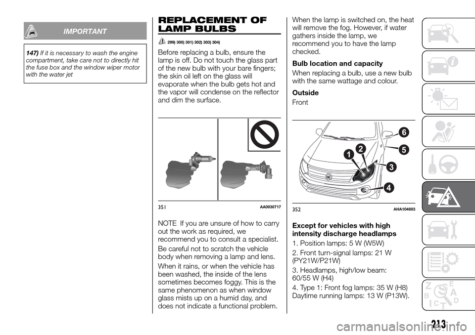
Except for vehicles with high
intensity discharge headlamps
1. Position lamps: 5 W (W5W)
2. Front turn-signal lamps: 21 W
(PY21W/P21W)
3. Headlamps, high/low beam:
60/55 W (H4)
4. Type 1: Front fog lamps: 35 W (H8)
Daytime running lamps: 13 W (P13W).
351AA0030717352AHA104603
213
Page 310 of 312
Masking the headlamps.........45
Multi information display.........86
Operation under adverse driving
conditions...............204
Outside rearview mirror.........38
Parking..................140
Parking brake...............139
Periodic checks.............240
Power steering fluid...........251
Pretensioners...............106
Read this carefully.............2
Rear Differential lock..........166
Rear gate..................29
Rear seat..................32
Rear view camera............180
Rear window demister switch.....67
Rearview mirrors..............37
Refill capacities..............292
Removal of water from the fuel filter......................188
Replacement of lamp bulbs......213
Safe driving techniques........134
safety systems..............126
SBR system................105
Scheduled Servicing Plan.......225
Seat adjustment..............31
Seat belt reminder............105
Seat belts
Use ...................103
Seats.....................31
Service precautions...........224
Side airbags................122
Sport mode................149
Starting and stopping the engine. . .141
Steering wheel...............35
Steering wheel height and reach
adjustment................35
Steering wheel lock............36
Sun visors..................74
Super Select 4WD II...........162
Supplemental restraint system
airbag..................118Tools, jack and jack handle......189
Towing...................201
Turbocharger operation........145
Turn-signal lever..............43
Tyres ....................260
Tyres and wheels.............291
Use of the Owner Handbook......3
Vanity mirror................75
Vehicle care precautions........255
Vehicle changes/alterations........5
Vehicle dimensions...........271
Vehicle labeling..............266
Vehicle performance..........279
Ventilators..................52
Washer fluid...............249
Weights..................281
Window...................68
Windscreen wiper.............48
Wiper and washer switch........48
Wiper blade rubber replacement . . .254
FCA Italy S.p.A. - MOPAR - Technical Services - Service Engineering
Largo Senatore G. Agnelli, 3 - 10040 Volvera - Turin (Italy)
Print no.
INDEX
Manual transmission..........146
603.99.982 - 04/2016- Edition1