dashboard FIAT GRANDE PUNTO 2010 199 / 1.G Owner's Manual
[x] Cancel search | Manufacturer: FIAT, Model Year: 2010, Model line: GRANDE PUNTO, Model: FIAT GRANDE PUNTO 2010 199 / 1.GPages: 216, PDF Size: 3.5 MB
Page 135 of 216
134
SAFETY
STARTING
AND DRIVING
IN AN
EMERGENCY
SERVICE
AND CARE
TECHNICAL
SPECIFICATIONS
INDEX
CONTROLS
AND DEVICES
WARNING
LIGHTS AND
MESSAGES
ASR SYSTEM
(versions with multifunction display)
The ASR system can be turned off by
pressing the button ASR OFF.
The display will show a specific message
to warn the driver that the system is off;
at the same time, the button LED will turn
on.
When you press button ASR OFFagain,
the button LED will turn off and the dis-
play will show a specific message to inform
the driver that the system is on again. POSSIBLE ICE ON ROAD
(versions with multifunction
display)
This starts flashing when the outside tem-
perature reaches or falls below 3 °C to
warn the driver of the possible presence
of ice on the road.
The display will show a specific message.
LIMITED RANGE
(versions with multifunction
display)
The display will show a specific message
to warn the driver that the cruising range
is less than 50 km. SPEED LIMIT EXCEEDED
The display will show a specific message
when the car exceeds the fixed speed lim-
it (see “Multifunction Display” in the
“Dashboard and controls” section).
123-134 ACTUAL 1ed EN 31-08-2010 9:24 Pagina 134
Page 137 of 216
136
SAFETY
STARTING
AND DRIVING
WARNING
LIGHTS AND
MESSAGES
SERVICE
AND CARE
TECHNICAL
SPECIFICATIONS
INDEX
CONTROLS
AND DEVICES
IN AN
EMERGENCY
STARTING THE ENGINE
EMERGENCY START-UP
If the instrument panel warning light
Ystays on permanently, contact a Fiat
Dealership immediately.
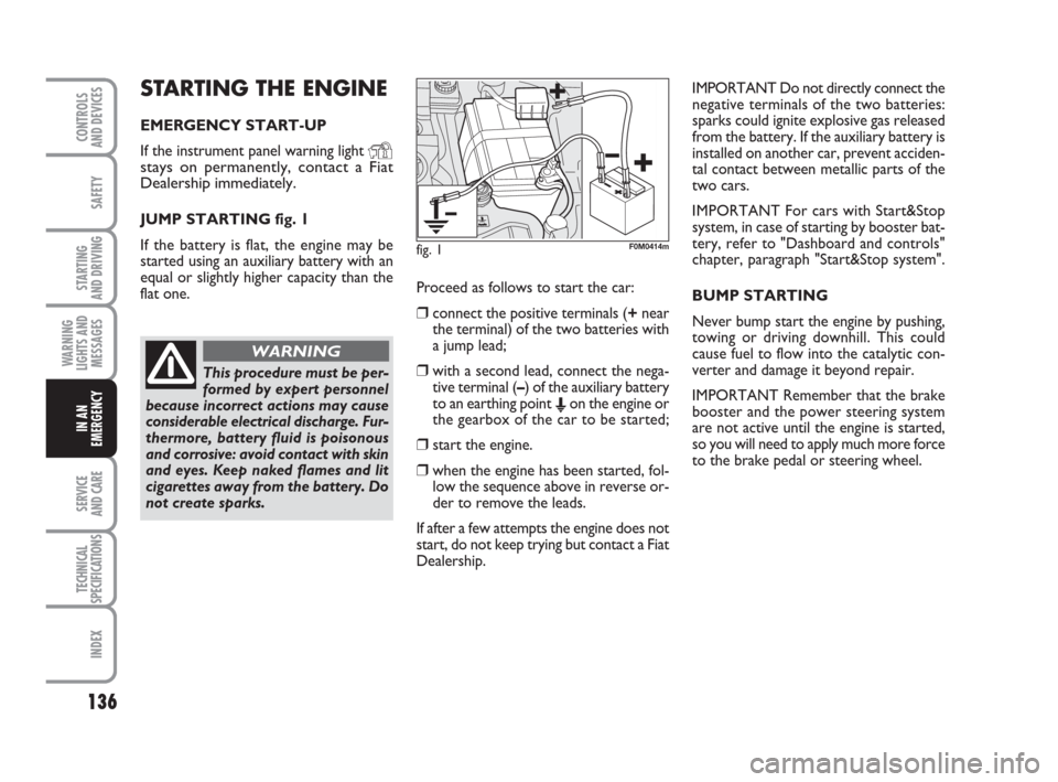
JUMP STARTING fig. 1
If the battery is flat, the engine may be
started using an auxiliary battery with an
equal or slightly higher capacity than the
flat one. Proceed as follows to start the car:
❒connect the positive terminals (+near
the terminal) of the two batteries with
a jump lead;
❒with a second lead, connect the nega-
tive terminal (–) of the auxiliary battery
to an earthing point
Eon the engine or
the gearbox of the car to be started;
❒start the engine.
❒when the engine has been started, fol-
low the sequence above in reverse or-
der to remove the leads.
If after a few attempts the engine does not
start, do not keep trying but contact a Fiat
Dealership.IMPORTANT Do not directly connect the
negative terminals of the two batteries:
sparks could ignite explosive gas released
from the battery. If the auxiliary battery is
installed on another car, prevent acciden-
tal contact between metallic parts of the
two cars.
IMPORTANT For cars with Start&Stop
system, in case of starting by booster bat-
tery, refer to "Dashboard and controls"
chapter, paragraph "Start&Stop system".
BUMP STARTING
Never bump start the engine by pushing,
towing or driving downhill. This could
cause fuel to flow into the catalytic con-
verter and damage it beyond repair.
IMPORTANT Remember that the brake
booster and the power steering system
are not active until the engine is started,
so you will need to apply much more force
to the brake pedal or steering wheel.
This procedure must be per-
formed by expert personnel
because incorrect actions may cause
considerable electrical discharge. Fur-
thermore, battery fluid is poisonous
and corrosive: avoid contact with skin
and eyes. Keep naked flames and lit
cigarettes away from the battery. Do
not create sparks.
WARNING
fig. 1F0M0414m
135-166 ACTUAL 1ed EN 26-07-2010 16:00 Pagina 136
Page 143 of 216
142
SAFETY
STARTING
AND DRIVING
WARNING
LIGHTS AND
MESSAGES
SERVICE
AND CARE
TECHNICAL
SPECIFICATIONS
INDEX
CONTROLS
AND DEVICES
IN AN
EMERGENCY
QUICK TYRE REPAIR KIT
FIX&GO automatic
The Fix&Go automatic quick tyre repair
kit is located in the boot.
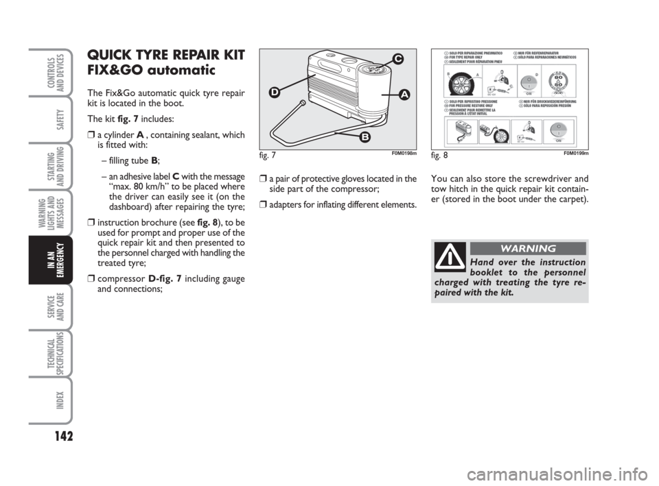
The kit fig. 7includes:
❒a cylinder A , containing sealant, which
is fitted with:
– filling tube B;
– an adhesive label Cwith the message
“max. 80 km/h” to be placed where
the driver can easily see it (on the
dashboard) after repairing the tyre;
❒instruction brochure (see fig. 8), to be
used for prompt and proper use of the
quick repair kit and then presented to
the personnel charged with handling the
treated tyre;
❒compressor D-fig. 7including gauge
and connections;
❒a pair of protective gloves located in the
side part of the compressor;
❒adapters for inflating different elements.
fig. 7F0M0198m
You can also store the screwdriver and
tow hitch in the quick repair kit contain-
er (stored in the boot under the carpet).
fig. 8F0M0199m
Hand over the instruction
booklet to the personnel
charged with treating the tyre re-
paired with the kit.
WARNING
135-166 ACTUAL 1ed EN 26-07-2010 16:00 Pagina 142
Page 157 of 216
156
SAFETY
STARTING
AND DRIVING
WARNING
LIGHTS AND
MESSAGES
SERVICE
AND CARE
TECHNICAL
SPECIFICATIONS
INDEX
CONTROLS
AND DEVICES
IN AN
EMERGENCY
ACCESSING THE FUSES
The fuses are grouped in three control
units: on the dashboard, in the engine
compartment and in the left-hand side of
the boot.
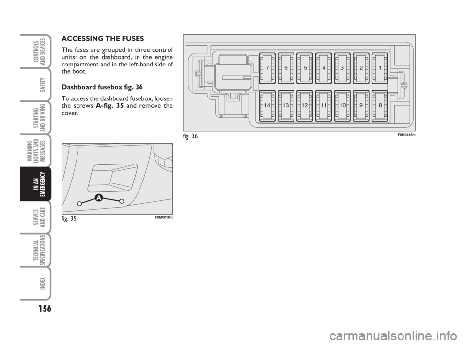
Dashboard fusebox fig. 36
To access the dashboard fusebox, loosen
the screws A-fig. 35and remove the
cover.
fig. 36F0M0415m
3 4 5 6 7
8 9 10 11 12
13 141 2
fig. 35F0M0016m
135-166 ACTUAL 1ed EN 26-07-2010 16:00 Pagina 156
Page 160 of 216
159
SAFETY
STARTING
AND DRIVING
WARNING
LIGHTS AND
MESSAGES
SERVICE
AND CARE
TECHNICAL
SPECIFICATIONS
INDEX
CONTROLS
AND DEVICES
IN AN
EMERGENCY
1
8
13
2
5
11
4
6
14
7
12
3
107,5
7,5
5
5
10
5
20
20
20
20
5
5
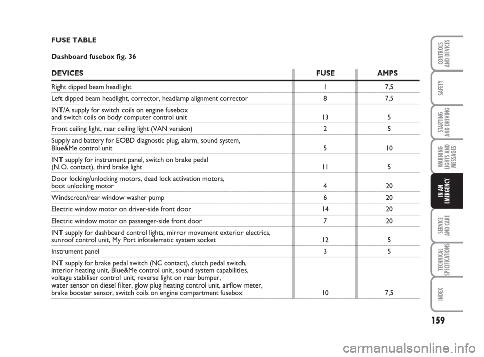
7,5 FUSE TABLE
Dashboard fusebox fig. 36
DEVICESFUSE AMPS
Right dipped beam headlight
Left dipped beam headlight, corrector, headlamp alignment corrector
INT/A supply for switch coils on engine fusebox
and switch coils on body computer control unit
Front ceiling light, rear ceiling light (VAN version)
Supply and battery for EOBD diagnostic plug, alarm, sound system,
Blue&Me control unit
INT supply for instrument panel, switch on brake pedal
(N.O. contact), third brake light
Door locking/unlocking motors, dead lock activation motors,
boot unlocking motor
Windscreen/rear window washer pump
Electric window motor on driver-side front door
Electric window motor on passenger-side front door
INT supply for dashboard control lights, mirror movement exterior electrics,
sunroof control unit, My Port infotelematic system socket
Instrument panel
INT supply for brake pedal switch (NC contact), clutch pedal switch,
interior heating unit, Blue&Me control unit, sound system capabilities,
voltage stabiliser control unit, reverse light on rear bumper,
water sensor on diesel filter, glow plug heating control unit, airflow meter,
brake booster sensor, switch coils on engine compartment fusebox
135-166 ACTUAL 1ed EN 26-07-2010 16:00 Pagina 159
Page 167 of 216
166
SAFETY
STARTING
AND DRIVING
WARNING
LIGHTS AND
MESSAGES
SERVICE
AND CARE
TECHNICAL
SPECIFICATIONS
INDEX
CONTROLS
AND DEVICES
IN AN
EMERGENCY
Do not start the engine while
the car is being towed.
WARNING
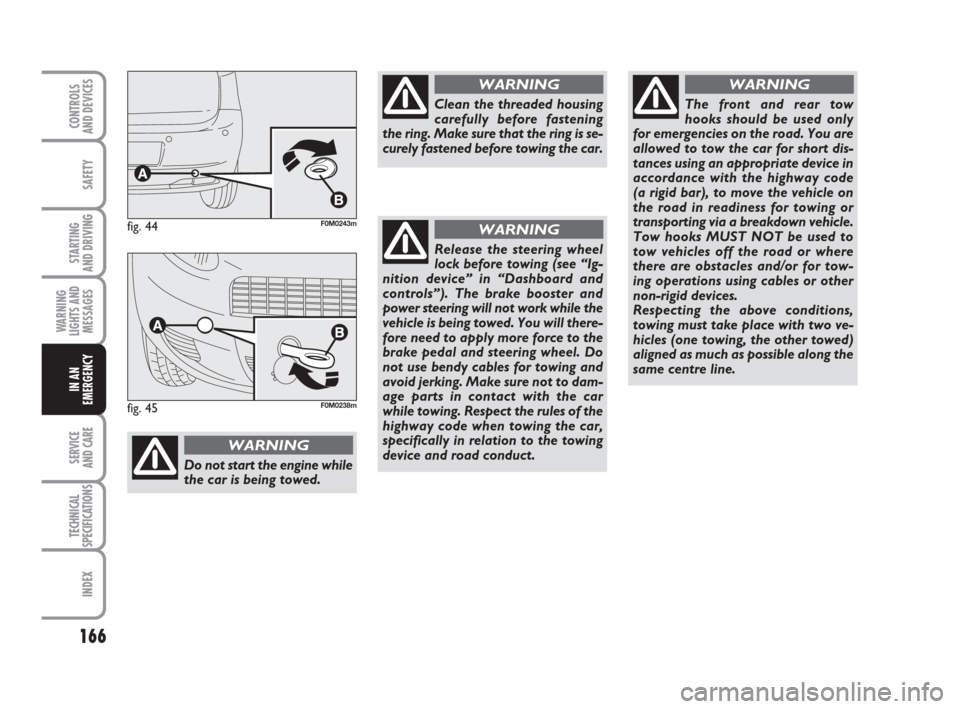
Clean the threaded housing
carefully before fastening
the ring. Make sure that the ring is se-
curely fastened before towing the car.
WARNING
Release the steering wheel
lock before towing (see “Ig-
nition device” in “Dashboard and
controls”). The brake booster and
power steering will not work while the
vehicle is being towed. You will there-
fore need to apply more force to the
brake pedal and steering wheel. Do
not use bendy cables for towing and
avoid jerking. Make sure not to dam-
age parts in contact with the car
while towing. Respect the rules of the
highway code when towing the car,
specifically in relation to the towing
device and road conduct.
WARNING
The front and rear tow
hooks should be used only
for emergencies on the road. You are
allowed to tow the car for short dis-
tances using an appropriate device in
accordance with the highway code
(a rigid bar), to move the vehicle on
the road in readiness for towing or
transporting via a breakdown vehicle.
Tow hooks MUST NOT be used to
tow vehicles off the road or where
there are obstacles and/or for tow-
ing operations using cables or other
non-rigid devices.
Respecting the above conditions,
towing must take place with two ve-
hicles (one towing, the other towed)
aligned as much as possible along the
same centre line.
WARNING
fig. 44F0M0243m
fig. 45F0M0238m
135-166 ACTUAL 1ed EN 26-07-2010 16:00 Pagina 166
Page 173 of 216
172
SAFETY
STARTING
AND DRIVING
WARNING
LIGHTS AND
MESSAGES
IN AN
EMERGENCY
TECHNICAL
SPECIFICATIONS
INDEX
CONTROLS
AND DEVICES
SERVICE
AND CARE
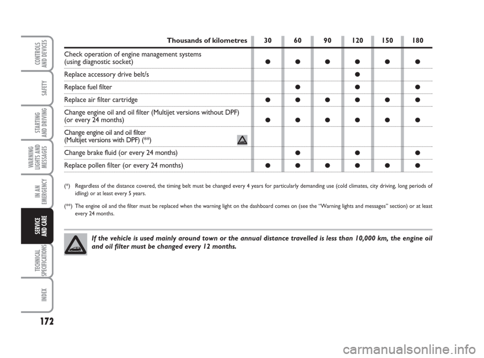
Thousands of kilometres
Check operation of engine management systems
(using diagnostic socket)
Replace accessory drive belt/s
Replace fuel filter
Replace air filter cartridge
Change engine oil and oil filter (Multijet versions without DPF)
(or every 24 months)
Change engine oil and oil filter
(Multijet versions with DPF) (**)
Change brake fluid (or every 24 months)
Replace pollen filter (or every 24 months)
(*) Regardless of the distance covered, the timing belt must be changed every 4 years for particularly demanding use (cold climates, city driving, long periods of
idling) or at least every 5 years.
(**) The engine oil and the filter must be replaced when the warning light on the dashboard comes on (see the “Warning lights and messages” section) or at least
every 24 months.
If the vehicle is used mainly around town or the annual distance travelled is less than 10,000 km, the engine oil
and oil filter must be changed every 12 months.
30 60 90 120 150 180
●●●●● ●
●
●● ●
●●●●● ●
●●●●● ●
●● ●
●●●●● ●
167-186 ACTUAL 1ed EN 27-07-2010 10:30 Pagina 172
Page 206 of 216
205
SAFETY
STARTING
AND DRIVING
WARNING
LIGHTS AND
MESSAGES
IN AN
EMERGENCY
SERVICE
AND CARE
TECHNICAL
SPECIFICATIONS
INDEX
CONTROLS
AND DEVICESBonnet ............................................ 70
Boot ................................................. 67
– opening the boot
in an emergency ...................... 67
– opening and closing
the boot .................................... 67
– extension .................................. 68
Boot extension .............................. 68
Brake Assist (emergency
braking assistance) ..................... 75
Brake fluid level ............................. 178
Brakes
– properties ................................. 193
– fluid level ................................... 178
Bulb (replacement)
– general information ................ 147
– bulb types ................................. 148
Car inactivity ................................ 122
Card/CD holder ........................... 58
Carrying children safely ............... 99
Ceiling lights ................................... 51
Changing a wheel .......................... 137
Chassis (marking) ......................... 188Checking levels ............................. 174
Child lock ....................................... 64
Child seats
(suitability for use) ............102-104
Cigarette lighter ............................ 58
Clutch .............................................. 192
CO
2emissions .............................. 204
Code Card ..................................... 8
Consumptions
– fuel ............................................. 204
– engine oil .................................. 176
Control buttons ............................ 53
Cup/can holder ............................. 58
Cup/can holders ............................ 58
Dashboard .................................... 5
Dashboard and controls ............. 4
Dead lock (device) ....................... 63
Digital display ................................. 16
Dimensions .................................... 198
Dipped beam headlights
– control ...................................... 47
– bulb replacement .................... 150
Ability to install
navigation system ....................... 88
ABS .................................................. 74
ABS system .................................... 74
Accessories purchased
by the owner ............................... 88
Air filter .......................................... 179
Alarm .............................................. 10
Arm rest ......................................... 57
Ashtray ........................................... 59
ASR .................................................. 77
– activation/deactivation ............ 77
ASR system .................................... 77
Battery
– jump starting ............................ 136
– checking the charge ............... 179
– recharging ................................. 163
– replacement ............................. 179
Bodywork
– maintenance ............................. 184
– version codes .......................... 190
I I
N N
D D
E E
X X
205-214 ACTUAL 1ed EN 26-07-2010 16:15 Pagina 205
Page 213 of 216
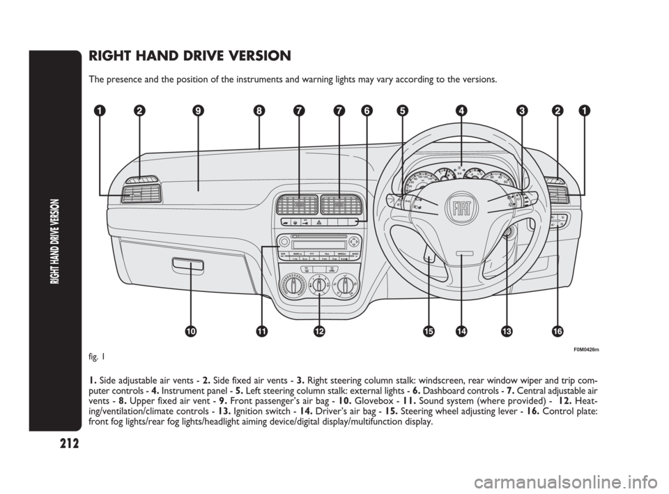
RIGHT HAND DRIVE VERSION
The presence and the position of the instruments and warning lights may vary according to the versions.
1. Side adjustable air vents - 2.Side fixed air vents - 3.Right steering column stalk: windscreen, rear window wiper and trip com-
puter controls - 4.Instrument panel - 5.Left steering column stalk: external lights - 6.Dashboard controls - 7.Central adjustable air
vents - 8.Upper fixed air vent - 9.Front passenger’s air bag - 10.Glovebox - 11.Sound system (where provided) - 12.Heat-
ing/ventilation/climate controls - 13.Ignition switch - 14.Driver’s air bag - 15.Steering wheel adjusting lever - 16.Control plate:
front fog lights/rear fog lights/headlight aiming device/digital display/multifunction display.
F0M0426mfig. 1
212
RIGHT HAND DRIVE VERSION
205-214 ACTUAL 1ed EN 26-07-2010 16:15 Pagina 212