boot FIAT GRANDE PUNTO ACTUAL 2015 1.G User Guide
[x] Cancel search | Manufacturer: FIAT, Model Year: 2015, Model line: GRANDE PUNTO ACTUAL, Model: FIAT GRANDE PUNTO ACTUAL 2015 1.GPages: 216, PDF Size: 3.66 MB
Page 70 of 216
69
SAFETY
STARTING
AND DRIVING
WARNING
LIGHTS AND
MESSAGES
IN AN
EMERGENCY
SERVICE
AND CARE
TECHNICAL
SPECIFICATIONS
INDEX
CONTROLS
AND DEVICES
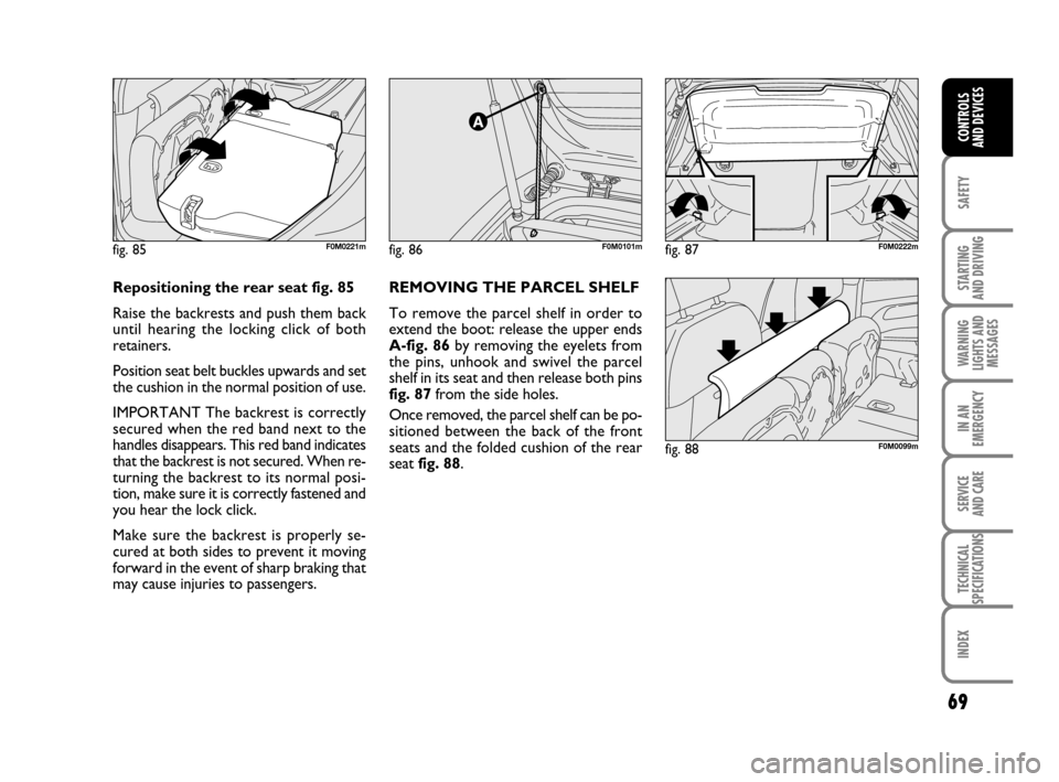
fig. 86F0M0101m
fig. 88F0M0099m
fig. 85F0M0221m
REMOVING THE PARCEL SHELF
To remove the parcel shelf in order to
extend the boot: release the upper ends
A-fig. 86by removing the eyelets from
the pins, unhook and swivel the parcel
shelf in its seat and then release both pins
fig. 87from the side holes.
Once removed, the parcel shelf can be po-
sitioned between the back of the front
seats and the folded cushion of the rear
seat fig. 88.
fig. 87F0M0222m
Repositioning the rear seat fig. 85
Raise the backrests and push them back
until hearing the locking click of both retainers.
Position seat belt buckles upwards and set
the cushion in the normal position of use.
IMPORTANT The backrest is correctly
secured when the red band next to the
handles disappears. This red band indicates
that the backrest is not secured. When re-
turning the backrest to its normal posi-
tion, make sure it is correctly fastened and
you hear the lock click.
Make sure the backrest is properly se-
cured at both sides to prevent it moving
forward in the event of sharp braking that
may cause injuries to passengers.
033-071 ACTUAL 1ed EN 18-01-2011 11:49 Pagina 69
Page 73 of 216
72
SAFETY
STARTING
AND DRIVING
WARNING
LIGHTS AND
MESSAGES
IN AN
EMERGENCY
SERVICE
AND CARE
TECHNICAL
SPECIFICATIONS
INDEX
CONTROLS
AND DEVICES
HEADLIGHTS
LIGHT BEAM DIRECTION
The correct direction of the headlights is
essential for the comfort and safety of the
driver and other road users. The head-
lights must be correctly directed to ensure
the best visibility. Contact a Fiat Dealer-
ship to have the direction checked and, if
necessary, adjusted.
HEADLIGHT ALIGNMENT
CORRECTOR
This device works with the key atMAR
and the dipped beam headlights on. The
car will slant backwards when it is loaded,
raising the light beam. The beams must
therefore be aimed again in this case.Headlight alignment adjustment
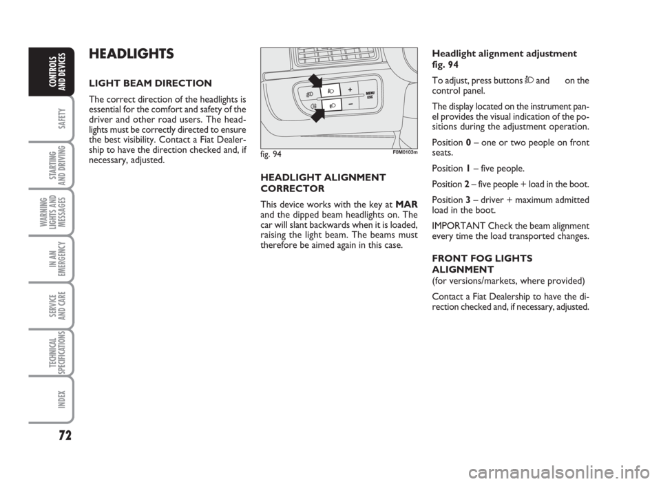
fig. 94
To adjust, press buttonsÒand on the
control panel.
The display located on the instrument pan-
el provides the visual indication of the po-
sitions during the adjustment operation.
Position0– one or two people on front
seats.
Position1– five people.
Position2– five people + load in the boot.
Position3– driver + maximum admitted
load in the boot.
IMPORTANT Check the beam alignment
every time the load transported changes.
FRONT FOG LIGHTS
ALIGNMENT
(for versions/markets, where provided)
Contact a Fiat Dealership to have the di-
rection checked and, if necessary, adjusted.
fig. 94F0M0103m
072-092 ACTUAL 1ed EN 26-07-2010 10:54 Pagina 72
Page 118 of 216
117
SAFETY
WARNING
LIGHTS AND
MESSAGES
IN AN
EMERGENCY
SERVICE
AND CARE
TECHNICAL
SPECIFICATIONS
INDEX
CONTROLS
AND DEVICES
STARTING
AND DRIVING
Roof rack/ski rack
Remove the roof rack or ski rack from the
roof after use. These accessories decrease
aerodynamic penetration and have a neg-
ative effect on fuel consumption. It is bet-
ter to use a trailer to transport particu-
larly bulky objects.
Electrical devices
Use electrical devices only for the amount
of time needed. The heated rear window,
auxiliary headlights, windscreen wipers and
fan heater use up a considerable amount
of current, causing increased fuel con-
sumption (up to +25% in the urban cycle).
Air conditioning
Air conditioning leads to higher fuel con-
sumption (on average up to +20%). If the
temperature outside is not too extreme,
try and use the air vents.
Spoilers
The use of non-certified spoilers may ad-
versely affect aerodynamics and fuel con-
sumption.DRIVING STYLE
Starting
Do not warm up the engine at low or high
revs when the vehicle is stationary; this
causes the engine to warm up more slow-
ly, thereby increasing fuel consumption
and emissions. It is advisable to set off im-
mediately and slowly, avoiding high revs:
this allows the engine to warm up more
quickly.
Unnecessary actions
Avoid revving up when stationary at traf-
fic lights or before stopping the engine.
The latter action, like double declutching,
is entirely unnecessary and causes in-
creased fuel consumption and pollution.
Gear selection
Use a higher gear as soon as traffic and
road conditions allow. Using a low gear
for faster acceleration will increase fuel
consumption.
In the same way, improper use of a high
gear increases fuel consumption, emissions
and engine wear.SAVING FUEL
Here are some suggestions which may
help you to save fuel and reduce the
amount of toxic emissions released into
the atmosphere.
GENERAL CONSIDERATIONS
Car maintenance
Have checks and adjustments carried out
in accordance with the “Scheduled Service
Plan”.
Tyres
Check the tyre pressure at least once
every 4 weeks: if the pressure is too low,
consumption levels increase as resistance
to rolling is higher.
Unnecessary loads
Do not travel with an overloaded boot.
The weight of the car (especially when dri-
ving in town) and its arrangement greatly
affect fuel consumption and stability.
111-122 ACTUAL 1ed EN 20-07-2010 16:10 Pagina 117
Page 128 of 216
127
SAFETY
STARTING
AND DRIVING
IN AN
EMERGENCY
SERVICE
AND CARE
TECHNICAL
SPECIFICATIONS
INDEX
CONTROLS
AND DEVICES
WARNING
LIGHTS AND
MESSAGES
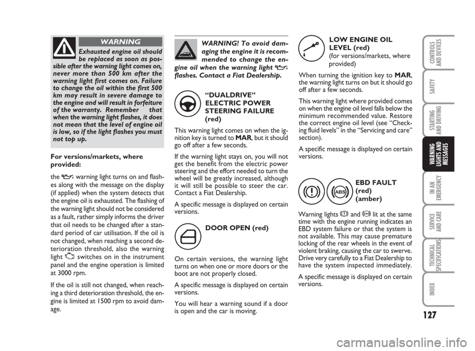
DOOR OPEN (red)
On certain versions, the warning light
turns on when one or more doors or the
boot are not properly closed.
A specific message is displayed on certain
versions.
You will hear a warning sound if a door
is open and the car is moving.
´
“DUALDRIVE”
ELECTRIC POWER
STEERING FAILURE
(red)
This warning light comes on when the ig-
nition key is turned to MAR, but it should
go off after a few seconds.
If the warning light stays on, you will not
get the benefit from the electric power
steering and the effort needed to turn the
wheel will be greatly increased, although
it will still be possible to steer the car.
Contact a Fiat Dealership.
A specific message is displayed on certain
versions.
g
EBD FAULT
(red)
(amber)
Warning lights
xand >lit at the same
time with the engine running indicates an
EBD system failure or that the system is
not available. This may cause premature
locking of the rear wheels in the event of
violent braking, causing the car to swerve.
Drive very carefully to a Fiat Dealership to
have the system inspected immediately.
A specific message is displayed on certain
versions.
x>
LOW ENGINE OIL
LEVEL (red)
(for versions/markets, where
provided)
When turning the ignition key to MAR,
the warning light turns on but it should go
off after a few seconds.
This warning light where provided comes
on when the engine oil level falls below the
minimum recommended value. Restore
the correct engine oil level (see “Check-
ing fluid levels” in the “Servicing and care”
section).
A specific message is displayed on certain
versions.
kExhausted engine oil should
be replaced as soon as pos-
sible after the warning light comes on,
never more than 500 km after the
warning light first comes on. Failure
to change the oil within the first 500
km may result in severe damage to
the engine and will result in forfeiture
of the warranty. Remember that
when the warning light flashes, it does
not mean that the level of engine oil
is low, so if the light flashes you must
not top up.
WARNING
For versions/markets, where
provided:
the
vwarning light turns on and flash-
es along with the message on the display
(if applied) when the system detects that
the engine oil is exhausted. The flashing of
the warning light should not be considered
as a fault, rather simply informs the driver
that oil needs to be changed after a stan-
dard period of car utilisation. If the oil is
not changed, when reaching a second de-
terioration threshold, also the warning
light
Uswitches on in the instrument
panel and the engine operation is limited
at 3000 rpm.
If the oil is still not changed, when reach-
ing a third deterioration threshold, the en-
gine is limited at 1500 rpm to avoid dam-
age.
WARNING! To avoid dam-
aging the engine it is recom-
mended to change the en-
gine oil when the warning light
v
flashes. Contact a Fiat Dealership.
123-134 ACTUAL 1ed EN 31-08-2010 9:23 Pagina 127
Page 139 of 216
138
SAFETY
STARTING
AND DRIVING
WARNING
LIGHTS AND
MESSAGES
SERVICE
AND CARE
TECHNICAL
SPECIFICATIONS
INDEX
CONTROLS
AND DEVICES
IN AN
EMERGENCY
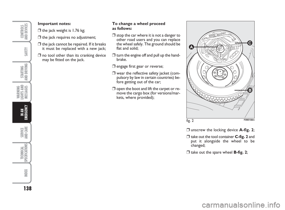
To change a wheel proceed
as follows:
❒stop the car where it is not a danger to
other road users and you can replace
the wheel safely. The ground should be
flat and solid;
❒turn the engine off and pull up the hand-
brake.
❒engage first gear or reverse;
❒ wear the reflective safety jacket (com-
pulsory by law in certain countries) be-
fore getting out of the car;
❒open the boot and lift the carpet or re-
move the cargo box (for versions/mar-
kets, where provided);
❒unscrew the locking device A-fig. 2;
❒take out the tool container C-fig. 2and
put it alongside the wheel to be
changed;
❒take out the spare wheel B-fig. 2;
fig. 2F0M0188m
Important notes:
❒the jack weight is 1.76 kg;
❒the jack requires no adjustment;
❒the jack cannot be repaired. If it breaks
it must be replaced with a new jack;
❒no tool other than its cranking device
may be fitted on the jack.
135-166 ACTUAL 1ed EN 26-07-2010 16:00 Pagina 138
Page 142 of 216
141
SAFETY
STARTING
AND DRIVING
WARNING
LIGHTS AND
MESSAGES
SERVICE
AND CARE
TECHNICAL
SPECIFICATIONS
INDEX
CONTROLS
AND DEVICES
IN AN
EMERGENCY
Versions with steel rims
Proceed as follows:
❒make sure the contact surfaces be-
tween standard wheel and hub are
clean so that the fastening bolts will not
come loose;
❒fit the standard wheel by inserting the
first bolt two threads into the hole clos-
est to the inflation valve;
❒fit the hub cap by aligning the crescent
hole with the bolt you have fitted, then
insert the other 3 bolts;
❒using the wrench provided, tighten the
fastening bolts;
❒lower the car and remove the jack;
❒using the wrench provided, fully tight-
en the bolts in the sequence shown
previously.Versions with alloy rims
Proceed as follows:
❒place the wheel onto the hub and tight-
en the bolts using the wrench provided;
❒lower the car and remove the jack;
❒using the wrench provided, fully tight-
en the bolts in the sequence shown
previously.When you have finished
❒stow the spare wheel in the space pro-
vided in the boot;
❒put the jack back in its container C-fig.
2partially open by forcing it slightly
against the container walls to prevent
it from rattling around when travelling;
❒put the tools back into their places in
the container;
❒stow the container C-fig. 2, complete
with tools, inside the spare wheel;
❒tighten the tool container clamping de-
vice A-fig. 2;
❒refit the boot carpet or the Cargo box
(for versions/markets, where provid-
ed).
135-166 ACTUAL 1ed EN 26-07-2010 16:00 Pagina 141
Page 143 of 216
142
SAFETY
STARTING
AND DRIVING
WARNING
LIGHTS AND
MESSAGES
SERVICE
AND CARE
TECHNICAL
SPECIFICATIONS
INDEX
CONTROLS
AND DEVICES
IN AN
EMERGENCY
QUICK TYRE REPAIR KIT
FIX&GO automatic
The Fix&Go automatic quick tyre repair
kit is located in the boot.
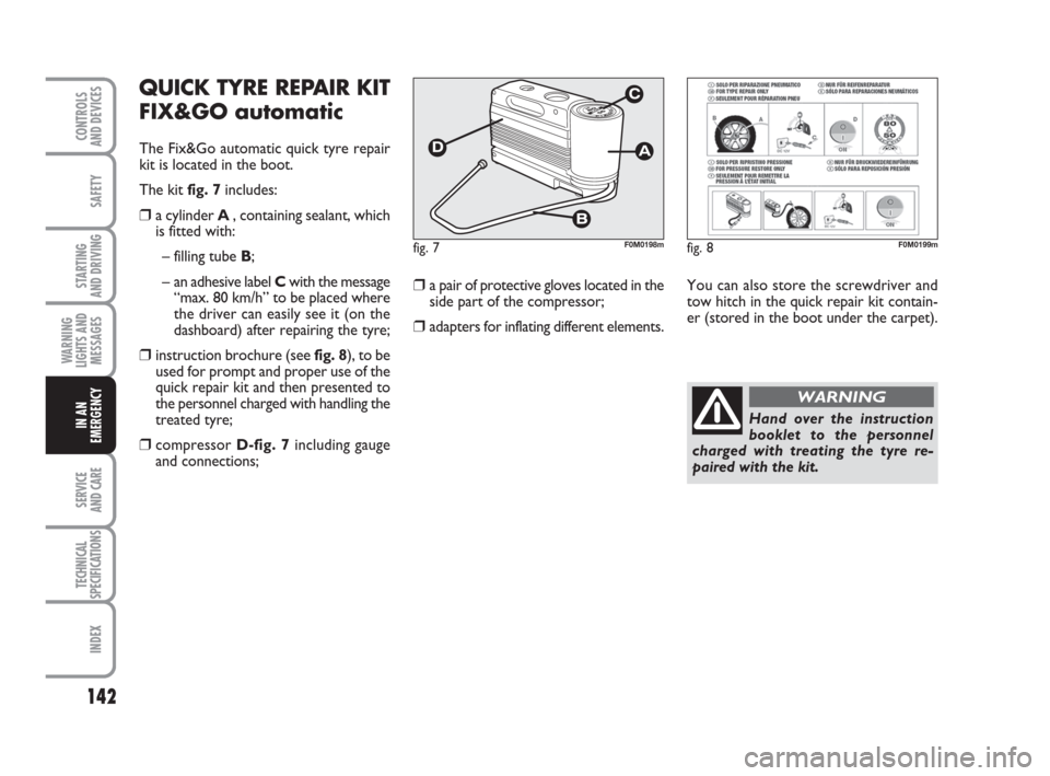
The kit fig. 7includes:
❒a cylinder A , containing sealant, which
is fitted with:
– filling tube B;
– an adhesive label Cwith the message
“max. 80 km/h” to be placed where
the driver can easily see it (on the
dashboard) after repairing the tyre;
❒instruction brochure (see fig. 8), to be
used for prompt and proper use of the
quick repair kit and then presented to
the personnel charged with handling the
treated tyre;
❒compressor D-fig. 7including gauge
and connections;
❒a pair of protective gloves located in the
side part of the compressor;
❒adapters for inflating different elements.
fig. 7F0M0198m
You can also store the screwdriver and
tow hitch in the quick repair kit contain-
er (stored in the boot under the carpet).
fig. 8F0M0199m
Hand over the instruction
booklet to the personnel
charged with treating the tyre re-
paired with the kit.
WARNING
135-166 ACTUAL 1ed EN 26-07-2010 16:00 Pagina 142
Page 153 of 216
152
SAFETY
STARTING
AND DRIVING
WARNING
LIGHTS AND
MESSAGES
SERVICE
AND CARE
TECHNICAL
SPECIFICATIONS
INDEX
CONTROLS
AND DEVICES
IN AN
EMERGENCY
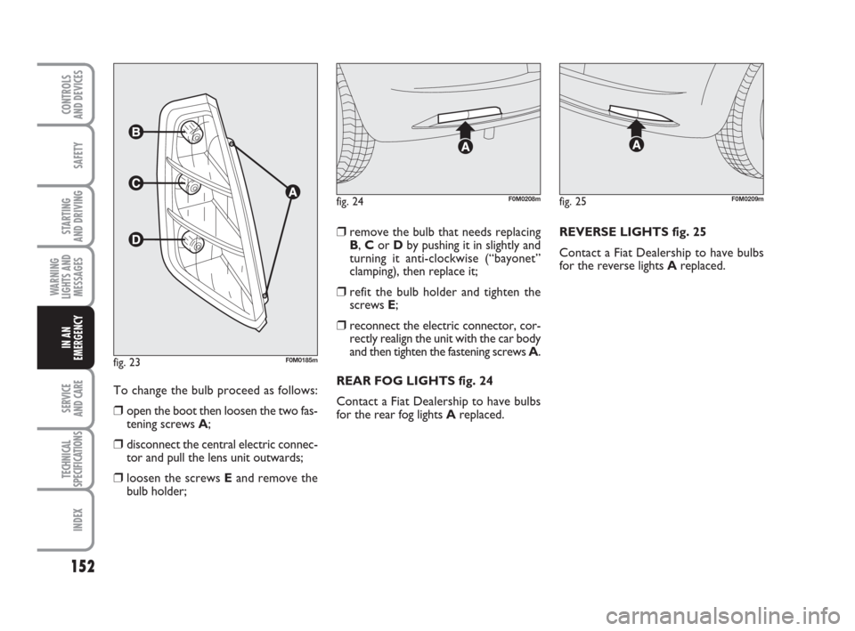
To change the bulb proceed as follows:
❒open the boot then loosen the two fas-
tening screws A;
❒disconnect the central electric connec-
tor and pull the lens unit outwards;
❒loosen the screws Eand remove the
bulb holder;
❒remove the bulb that needs replacing
B, Cor Dby pushing it in slightly and
turning it anti-clockwise (“bayonet”
clamping), then replace it;
❒refit the bulb holder and tighten the
screws E;
❒reconnect the electric connector, cor-
rectly realign the unit with the car body
and then tighten the fastening screws A.
REAR FOG LIGHTS fig. 24
Contact a Fiat Dealership to have bulbs
for the rear fog lights Areplaced.REVERSE LIGHTS fig. 25
Contact a Fiat Dealership to have bulbs
for the reverse lights Areplaced.
fig. 24F0M0208mfig. 25F0M0209m
fig. 23F0M0185m
135-166 ACTUAL 1ed EN 26-07-2010 16:00 Pagina 152
Page 154 of 216
153
SAFETY
STARTING
AND DRIVING
WARNING
LIGHTS AND
MESSAGES
SERVICE
AND CARE
TECHNICAL
SPECIFICATIONS
INDEX
CONTROLS
AND DEVICES
IN AN
EMERGENCY
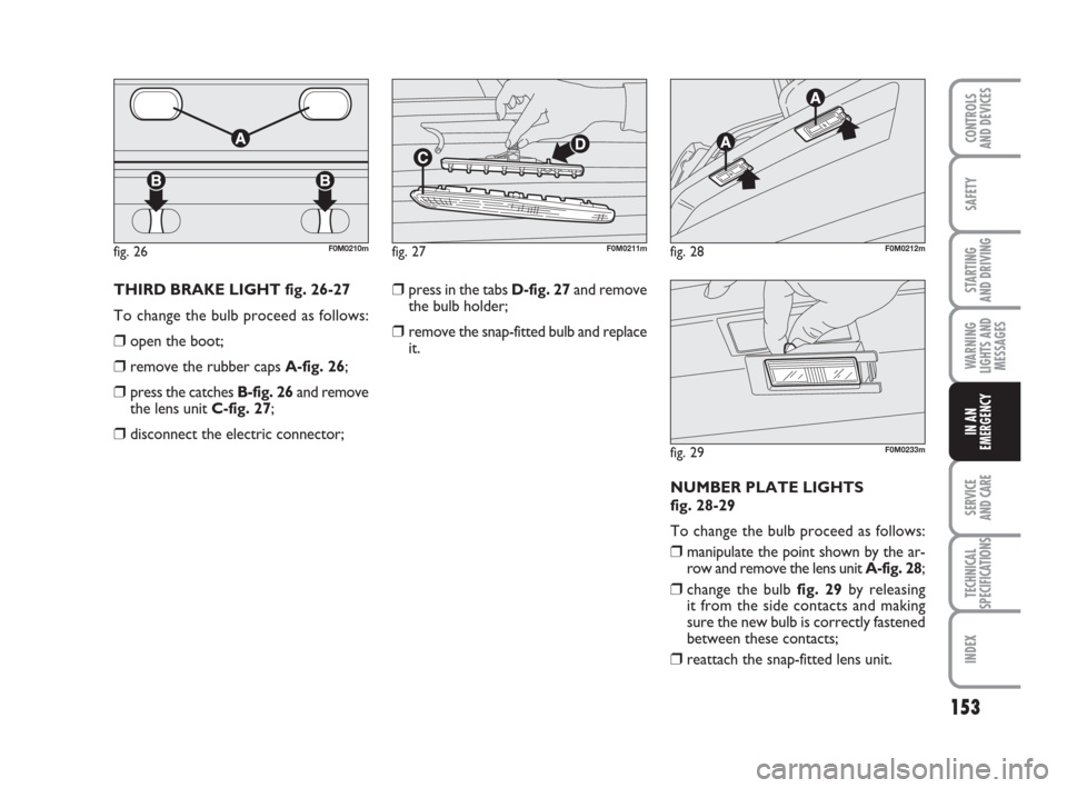
THIRD BRAKE LIGHT fig. 26-27
To change the bulb proceed as follows:
❒open the boot;
❒remove the rubber caps A-fig. 26;
❒press the catches B-fig. 26and remove
the lens unit C-fig. 27;
❒disconnect the electric connector;
❒press in the tabs D-fig. 27and remove
the bulb holder;
❒remove the snap-fitted bulb and replace
it.
NUMBER PLATE LIGHTS
fig. 28-29
To change the bulb proceed as follows:
❒manipulate the point shown by the ar-
row and remove the lens unit A-fig. 28;
❒change the bulb fig. 29by releasing
it from the side contacts and making
sure the new bulb is correctly fastened
between these contacts;
❒reattach the snap-fitted lens unit.
fig. 26F0M0210mfig. 27F0M0211mfig. 28F0M0212m
fig. 29F0M0233m
135-166 ACTUAL 1ed EN 26-07-2010 16:00 Pagina 153
Page 157 of 216
156
SAFETY
STARTING
AND DRIVING
WARNING
LIGHTS AND
MESSAGES
SERVICE
AND CARE
TECHNICAL
SPECIFICATIONS
INDEX
CONTROLS
AND DEVICES
IN AN
EMERGENCY
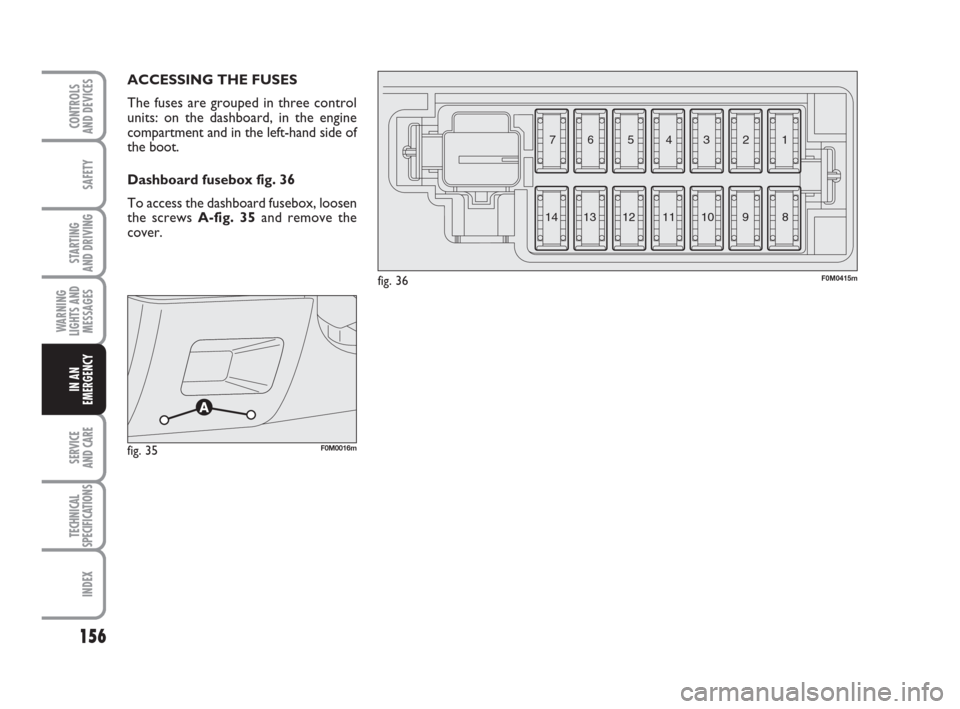
ACCESSING THE FUSES
The fuses are grouped in three control
units: on the dashboard, in the engine
compartment and in the left-hand side of
the boot.
Dashboard fusebox fig. 36
To access the dashboard fusebox, loosen
the screws A-fig. 35and remove the
cover.
fig. 36F0M0415m
3 4 5 6 7
8 9 10 11 12
13 141 2
fig. 35F0M0016m
135-166 ACTUAL 1ed EN 26-07-2010 16:00 Pagina 156