FIAT IDEA 2009 1.G Repair Manual
Manufacturer: FIAT, Model Year: 2009, Model line: IDEA, Model: FIAT IDEA 2009 1.GPages: 210, PDF Size: 3.62 MB
Page 61 of 210
60
SAFETY
STARTING
AND DRIVING
WARNING
LIGHTS AND
MESSAGES
IN AN
EMERGENCY
MAINTENANCE
AND CARE
TECHNICAL
SPECIFICATIONS
ALPHABETICAL
INDEX
DASHBOARD
AND CONTROLS
WINDOW CLEANING
WINDSCREEN WASHER/
WIPER
The device can only work when the igni-
tion key is at MAR.
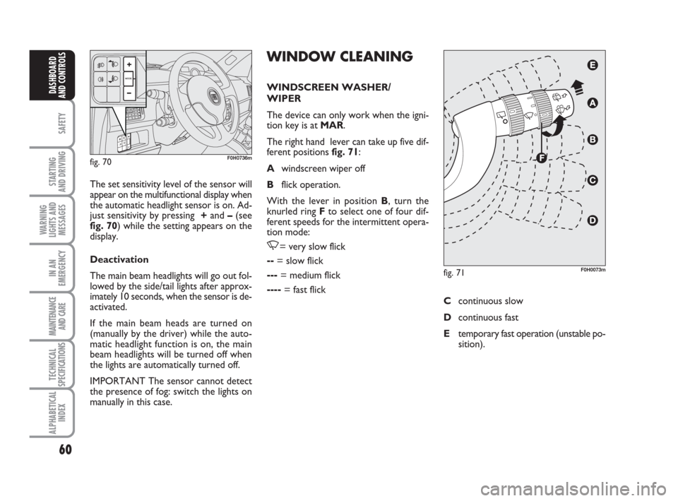
The right hand lever can take up five dif-
ferent positions fig. 71:
Awindscreen wiper off
Bflick operation.
With the lever in position B, turn the
knurled ring Fto select one of four dif-
ferent speeds for the intermittent opera-
tion mode:
,= very slow flick
--= slow flick
---= medium flick
----= fast flick The set sensitivity level of the sensor will
appear on the multifunctional display when
the automatic headlight sensor is on. Ad-
just sensitivity by pressing +and –(see
fig. 70) while the setting appears on the
display.
Deactivation
The main beam headlights will go out fol-
lowed by the side/tail lights after approx-
imately 10 seconds, when the sensor is de-
activated.
If the main beam heads are turned on
(manually by the driver) while the auto-
matic headlight function is on, the main
beam headlights will be turned off when
the lights are automatically turned off.
IMPORTANT The sensor cannot detect
the presence of fog: switch the lights on
manually in this case.
fig. 70F0H0736m
fig. 71F0H0073m
Ccontinuous slow
Dcontinuous fast
Etemporary fast operation (unstable po-
sition).
Page 62 of 210
61
SAFETY
STARTING
AND DRIVING
WARNING
LIGHTS AND
MESSAGES
IN AN
EMERGENCY
MAINTENANCE
AND CARE
TECHNICAL
SPECIFICATIONS
ALPHABETICAL
INDEX
DASHBOARD
AND CONTROLS
Operation in position Eis limited to the
time during which the lever is kept in that
position manually. When released, the
stalk will return to position Aand the
wiper will be automatically stopped.
IMPORTANT Replace wiper blades as
specified in the “Maintenance and care”
chapter. RAIN SENSOR
(where provided)
The rain sensor is located behind the dri-
ving mirror in contact with the windscreen
and has the purpose of automatically ad-
justing the frequency of the windscreen
wiper strokes as to the rain intensity.
IMPORTANT Keep clean the glass in the
sensor area.
Activation
Move the right stalk down by one click.
The activation of the rain sensor is sig-
nalled by a control acquisition flick.
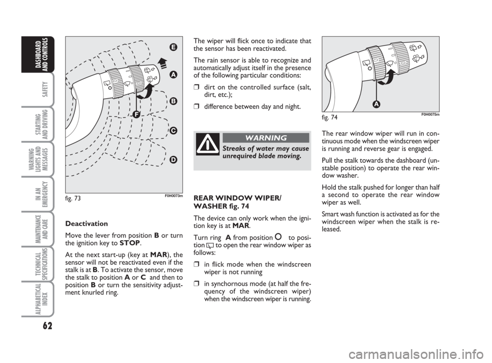
Turn the ring F-fig. 73to increase the rain
sensor sensitivity.
The increase of the sensitivity of the rain
sensor is signalled by a control and acqui-
sition flick.
The smart cycle is started when the wind-
screen wiper is turned on while the rain
sensor is active without supplementary
flick after 5 seconds. The sensor will re-
sume normal automatic operation. “Smart wash” function
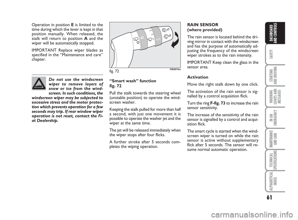
fig. 72
Pull the stalk towards the steering wheel
(unstable position) to operate the wind-
screen washer.
Keeping the stalk pulled for more than half
a second, with just one movement it is
possible to operate the washer jet and the
wiper at the same time.
The jet will be released immediately when
the wiper stops after four flicks.
A further stroke after 5 seconds com-
pletes the wiping operation. Do not use the windscreen
wiper to remove layers of
snow or ice from the wind-
screen. In such conditions, the
windscreen wiper may be subjected to
excessive stress and the motor protec-
tion which prevents operation for a few
seconds may trip. If rear window wiper
operation is not reset, contact the Fi-
at Dealership.
fig. 72F0H0074m
Page 63 of 210
62
SAFETY
STARTING
AND DRIVING
WARNING
LIGHTS AND
MESSAGES
IN AN
EMERGENCY
MAINTENANCE
AND CARE
TECHNICAL
SPECIFICATIONS
ALPHABETICAL
INDEX
DASHBOARD
AND CONTROLS
The wiper will flick once to indicate that
the sensor has been reactivated.
The rain sensor is able to recognize and
automatically adjust itself in the presence
of the following particular conditions:
❒dirt on the controlled surface (salt,
dirt, etc.);
❒difference between day and night.
Deactivation
Move the lever from position Bor turn
the ignition key to STOP.
At the next start-up (key at MAR), the
sensor will not be reactivated even if the
stalk is at B. To activate the sensor, move
the stalk to position Aor C and then to
position Bor turn the sensitivity adjust-
ment knurled ring.
fig. 73F0H0073m
Streaks of water may cause
unrequired blade moving.
WARNINGThe rear window wiper will run in con-
tinuous mode when the windscreen wiper
is running and reverse gear is engaged.
Pull the stalk towards the dashboard (un-
stable position) to operate the rear win-
dow washer.
Hold the stalk pushed for longer than half
a second to operate the rear window
wiper as well.
Smart wash function is activated as for the
windscreen wiper when the stalk is re-
leased.
fig. 74F0H0075m
REAR WINDOW WIPER/
WASHER fig. 74
The device can only work when the igni-
tion key is at MAR.
Turn ring Afrom position
åto posi-
tion
'to open the rear window wiper as
follows:
❒in flick mode when the windscreen
wiper is not running
❒in synchornous mode (at half the fre-
quency of the windscreen wiper)
when the windscreen wiper is running.
Page 64 of 210

63
SAFETY
STARTING
AND DRIVING
WARNING
LIGHTS AND
MESSAGES
IN AN
EMERGENCY
MAINTENANCE
AND CARE
TECHNICAL
SPECIFICATIONS
ALPHABETICAL
INDEX
DASHBOARD
AND CONTROLS
CRUISE CONTROL
(constant speed
regulator) (where
provided)
It is a device able to support the driver,
with electronic control, which allows dri-
ving at speed over 30 km/h on long and
straight dry roads (e.g.: motorways), at a
desired speed, without pressing the ac-
celerator pedal. Therefore it is not sug-
gested to use this device on extra-urban
roads with traffic. Do not use it in town.
TURING THE DEVICE ON
Turn the ring A-fig. 75to ON.
The device can be turned on in 4th or 5th
gear only. Travelling downhill with the de-
vice engaged, the car speed may increase
more than the memorised one.
When the device is activated the warn-
ing light
Üturns on together with the rel-
evant message on the instrument panel
(where provided).
fig. 75F0H0074m
STORING THE SPEED
Proceed as follows:
❒turn ring A-fig. 75to ONand press
the accelerator pedal to the required
speed;
❒push the lever upwards (+) for at
least 1 second, then release it: the
car speed will be stored. The accel-
erator pedal may be released.
If needed (e.g. for overtaking), press the
accelerator pedal to accelerate: the car
will return to the previously set speed
when the pedal is released.RESTORING MEMORIZED
SPEED
If the device has been disengaged, for ex-
ample by pressing the brake or clutch ped-
al, the memorized speed can be reset as
follows:
❒accelerate gradually until reaching a
speed approaching the stored speed;
❒engage the gear selected when the
speed was stored (4th or 5th gear);
❒press button RES B-fig. 75.
INCREASING THE MEMORIZED
SPEED
The stored speed can be increased in two
ways:
❒by pressing the accelerator and then
storing the new speed reached;
or
❒ by moving the stalk upwards (+).
Each operation of the stalk will correspond
to a slight increase in speed (about 1 km/h),
while keeping the stalk upwards will cor-
respond to a continuous speed increase.
When travelling with the de-
vice on, never set the
gearshift lever to neutral.
WARNING
Page 65 of 210
64
SAFETY
STARTING
AND DRIVING
WARNING
LIGHTS AND
MESSAGES
IN AN
EMERGENCY
MAINTENANCE
AND CARE
TECHNICAL
SPECIFICATIONS
ALPHABETICAL
INDEX
DASHBOARD
AND CONTROLS
REDUCING THE MEMORIZED
SPEED
The stored speed can be increased in two
ways:
❒by turning the device off and then
storing a new speed;
or
❒ moving the stalk downwards (–) until
reaching the new speed which will be
memorised automatically.
Each movement of the lever will corre-
spond to a slight reduction in speed (about
1 km/h), while keeping the lever held
downwards will correspond to a continu-
ous speed reduction.
DISENGAGING THE DEVICE
Turn ring A-fig. 75to OFFor the igni-
tion key to STOP. If the device has been
disengaged, for example by pressing the
brake or clutch pedal.
If the device is faulty, turn
ring A to OFF, check the fuse
and contact a Fiat Dealership.
WARNING
COURTESY LIGHTS
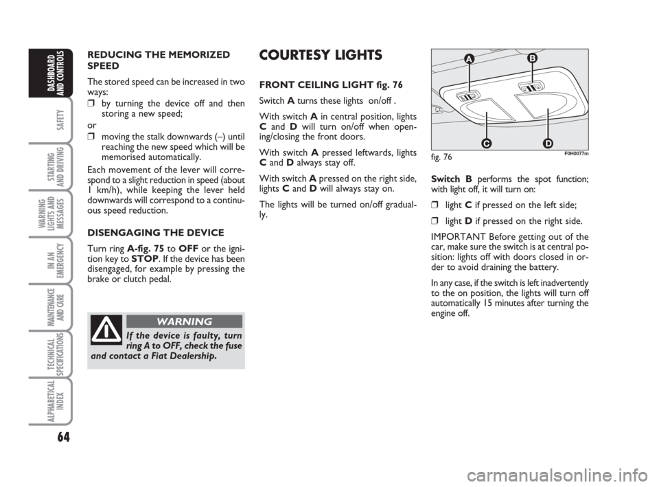
FRONT CEILING LIGHT fig. 76
Switch Aturns these lights on/off .
With switch Ain central position, lights
Cand Dwill turn on/off when open-
ing/closing the front doors.
With switch Apressed leftwards, lights
Cand Dalways stay off.
With switch Apressed on the right side,
lights C andD will always stay on.
The lights will be turned on/off gradual-
ly.Switch Bperforms the spot function;
with light off, it will turn on:
❒ light Cif pressed on the left side;
❒light Dif pressed on the right side.
IMPORTANT Before getting out of the
car, make sure the switch is at central po-
sition: lights off with doors closed in or-
der to avoid draining the battery.
In any case, if the switch is left inadvertently
to the on position, the lights will turn off
automatically 15 minutes after turning the
engine off.
fig. 76F0H0077m
Page 66 of 210
65
SAFETY
STARTING
AND DRIVING
WARNING
LIGHTS AND
MESSAGES
IN AN
EMERGENCY
MAINTENANCE
AND CARE
TECHNICAL
SPECIFICATIONS
ALPHABETICAL
INDEX
DASHBOARD
AND CONTROLS
fig. 77F0H0078mfig. 78F0H0079m
fig. 79F0H0254m
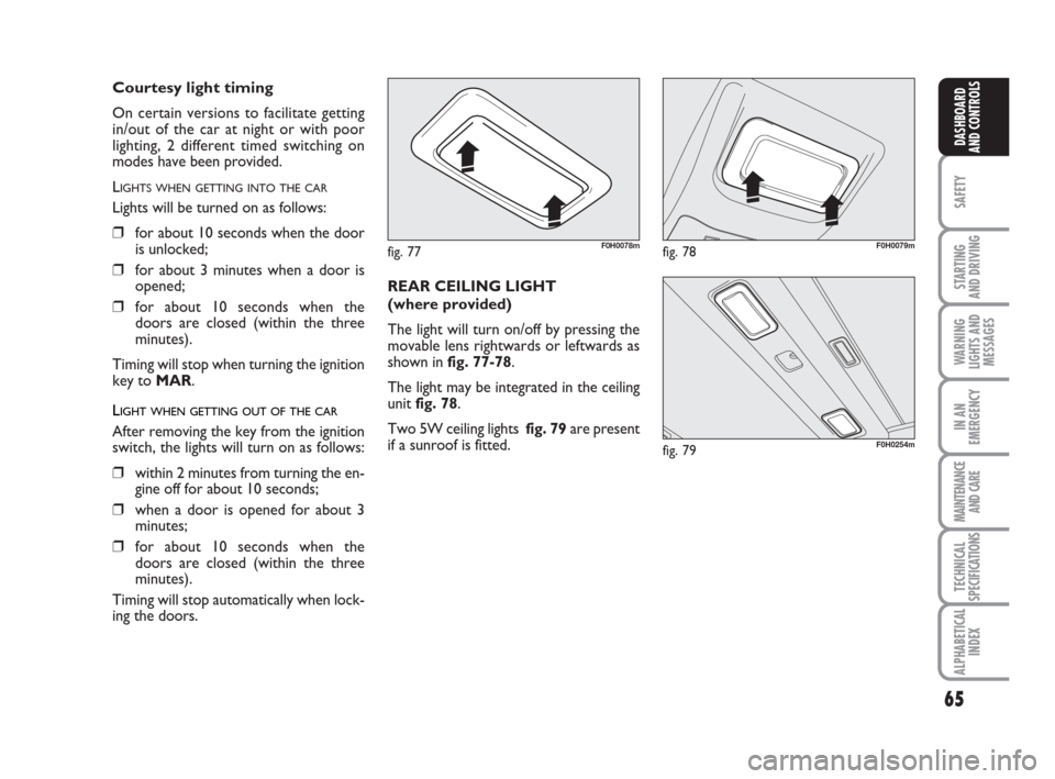
REAR CEILING LIGHT
(where provided)
The light will turn on/off by pressing the
movable lens rightwards or leftwards as
shown in fig. 77-78.
The light may be integrated in the ceiling
unit fig. 78.
Two 5W ceiling lights fig. 79are present
if a sunroof is fitted.
Courtesy light timing
On certain versions to facilitate getting
in/out of the car at night or with poor
lighting, 2 different timed switching on
modes have been provided.
L
IGHTS WHEN GETTING INTO THE CAR
Lights will be turned on as follows:
❒for about 10 seconds when the door
is unlocked;
❒for about 3 minutes when a door is
opened;
❒for about 10 seconds when the
doors are closed (within the three
minutes).
Timing will stop when turning the ignition
key to MAR.
LIGHT WHEN GETTING OUT OF THE CAR
After removing the key from the ignition
switch, the lights will turn on as follows:
❒within 2 minutes from turning the en-
gine off for about 10 seconds;
❒when a door is opened for about 3
minutes;
❒for about 10 seconds when the
doors are closed (within the three
minutes).
Timing will stop automatically when lock-
ing the doors.
Page 67 of 210
66
SAFETY
STARTING
AND DRIVING
WARNING
LIGHTS AND
MESSAGES
IN AN
EMERGENCY
MAINTENANCE
AND CARE
TECHNICAL
SPECIFICATIONS
ALPHABETICAL
INDEX
DASHBOARD
AND CONTROLS
HAZARD LIGHTS
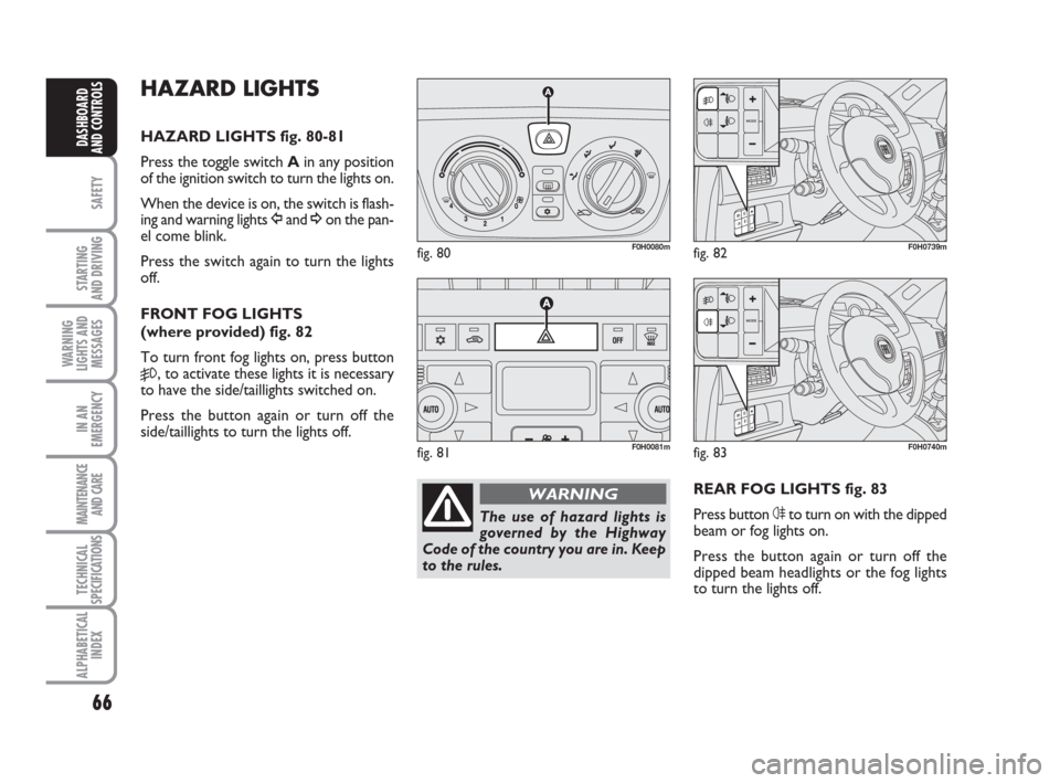
HAZARD LIGHTS fig. 80-81
Press the toggle switch Ain any position
of the ignition switch to turn the lights on.
When the device is on, the switch is flash-
ing and warning lights Îand ¥on the pan-
el come blink.
Press the switch again to turn the lights
off.
FRONT FOG LIGHTS
(where provided) fig. 82
To turn front fog lights on, press button
5, to activate these lights it is necessary
to have the side/taillights switched on.
Press the button again or turn off the
side/taillights to turn the lights off.
REAR FOG LIGHTS fig. 83
Press button 4to turn on with the dipped
beam or fog lights on.
Press the button again or turn off the
dipped beam headlights or the fog lights
to turn the lights off.
fig. 80F0H0080m
fig. 81F0H0081m
fig. 82F0H0739m
The use of hazard lights is
governed by the Highway
Code of the country you are in. Keep
to the rules.
WARNING
fig. 83F0H0740m
Page 68 of 210
67
SAFETY
STARTING
AND DRIVING
WARNING
LIGHTS AND
MESSAGES
IN AN
EMERGENCY
MAINTENANCE
AND CARE
TECHNICAL
SPECIFICATIONS
ALPHABETICAL
INDEX
DASHBOARD
AND CONTROLS
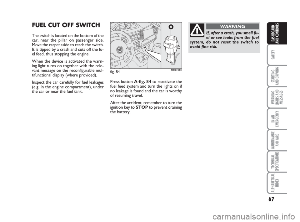
FUEL CUT OFF SWITCH
The switch is located on the bottom of the
car, near the pillar on passenger side.
Move the carpet aside to reach the switch.
It is tipped by a crash and cuts off the fu-
el feed, thus stopping the engine.
When the device is activated the warn-
ing light turns on together with the rele-
vant message on the reconfigurable mul-
tifunctional display (where provided).
Inspect the car carefully for fuel leakages
(e.g. in the engine compartment), under
the car or near the fuel tank. Press button A-fig. 84to reactivate the
fuel feed system and turn the lights on if
no leakage is found and the car is worthy
of resuming travel.
After the accident, remember to turn the
ignition key to STOPto prevent draining
the battery.
fig. 84F0H0741m
If, after a crash, you smell fu-
el or see leaks from the fuel
system, do not reset the switch to
avoid fine risk.
WARNING
Page 69 of 210
68
SAFETY
STARTING
AND DRIVING
WARNING
LIGHTS AND
MESSAGES
IN AN
EMERGENCY
MAINTENANCE
AND CARE
TECHNICAL
SPECIFICATIONS
ALPHABETICAL
INDEX
DASHBOARD
AND CONTROLS
INTERIOR EQUIPMENT
UPPER ODDMENT
COMPARTMENTS
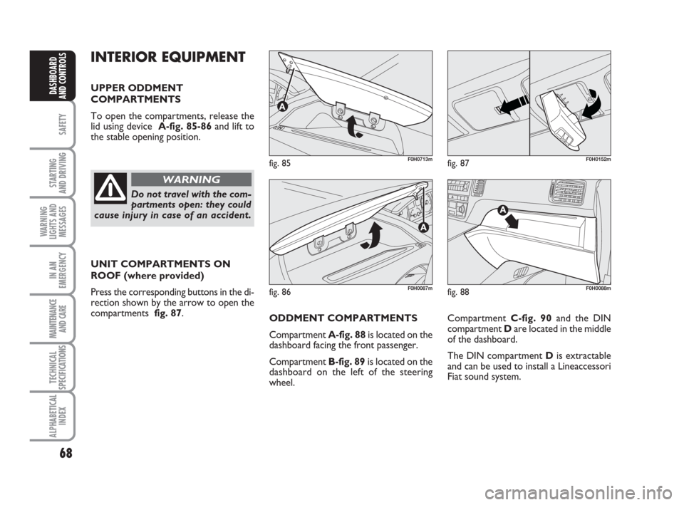
To open the compartments, release the
lid using device A-fig. 85-86 and lift to
the stable opening position.
UNIT COMPARTMENTS ON
ROOF (where provided)
Press the corresponding buttons in the di-
rection shown by the arrow to open the
compartments fig. 87.
fig. 85F0H0713m
fig. 86F0H0087m
fig. 87F0H0152m
Do not travel with the com-
partments open: they could
cause injury in case of an accident.
WARNING
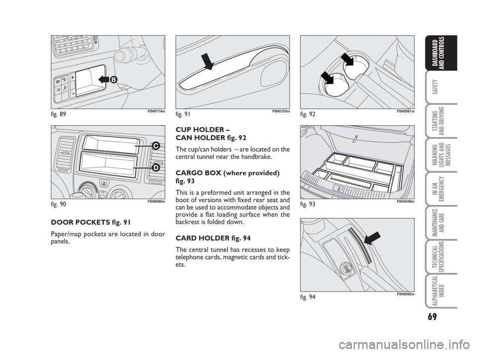
Compartment C-fig. 90and the DIN
compartment Dare located in the middle
of the dashboard.
The DIN compartment Dis extractable
and can be used to install a Lineaccessori
Fiat sound system.
fig. 88F0H0088m
ODDMENT COMPARTMENTS
Compartment A-fig. 88is located on the
dashboard facing the front passenger.
Compartment B-fig. 89is located on the
dashboard on the left of the steering
wheel.
Page 70 of 210
69
SAFETY
STARTING
AND DRIVING
WARNING
LIGHTS AND
MESSAGES
IN AN
EMERGENCY
MAINTENANCE
AND CARE
TECHNICAL
SPECIFICATIONS
ALPHABETICAL
INDEX
DASHBOARD
AND CONTROLS
fig. 90F0H0090m
fig. 89F0H0714m
DOOR POCKETS fig. 91
Paper/map pockets are located in door
panels.CUP HOLDER –
CAN HOLDER fig. 92
The cup/can holders – are located on the
central tunnel near the handbrake.
CARGO BOX (where provided)
fig. 93
This is a preformed unit arranged in the
boot of versions with fixed rear seat and
can be used to accommodate objects and
provide a flat loading surface when the
backrest is folded down.
CARD HOLDER fig. 94
The central tunnel has recesses to keep
telephone cards, magnetic cards and tick-
ets.
fig. 91F0H0153mfig. 92F0H0091m
fig. 93F0H0349m
fig. 94F0H0092m