ECO mode FIAT IDEA 2009 1.G Owners Manual
[x] Cancel search | Manufacturer: FIAT, Model Year: 2009, Model line: IDEA, Model: FIAT IDEA 2009 1.GPages: 210, PDF Size: 3.62 MB
Page 22 of 210
21
SAFETY
STARTING
AND DRIVING
WARNING
LIGHTS AND
MESSAGES
IN AN
EMERGENCY
MAINTENANCE
AND CARE
TECHNICAL
SPECIFICATIONS
ALPHABETICAL
INDEX
DASHBOARD
AND CONTROLS
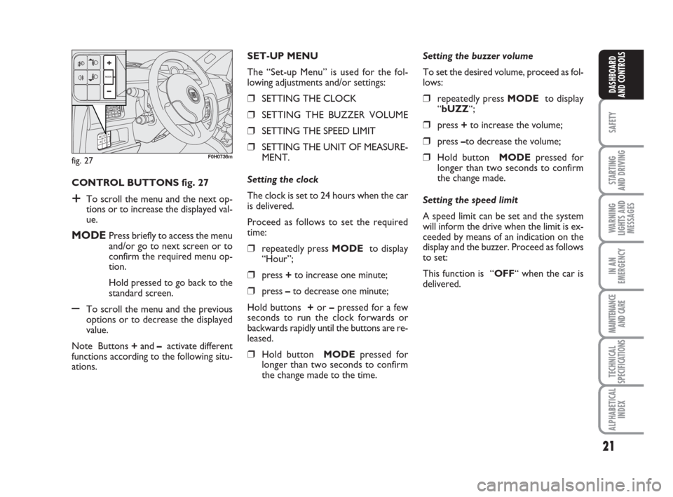
CONTROL BUTTONS fig. 27
+To scroll the menu and the next op-
tions or to increase the displayed val-
ue.
MODEPress briefly to access the menu
and/or go to next screen or to
confirm the required menu op-
tion.
Hold pressed to go back to the
standard screen.
–To scroll the menu and the previous
options or to decrease the displayed
value.
Note Buttons +and –activate different
functions according to the following situ-
ations.Setting the buzzer volume
To set the desired volume, proceed as fol-
lows:
❒repeatedly press MODE to display
“bUZZ“;
❒press +to increase the volume;
❒press –to decrease the volume;
❒Hold button MODEpressed for
longer than two seconds to confirm
the change made.
Setting the speed limit
A speed limit can be set and the system
will inform the drive when the limit is ex-
ceeded by means of an indication on the
display and the buzzer. Proceed as follows
to set:
This function is “OFF“ when the car is
delivered. SET-UP MENU
The “Set-up Menu” is used for the fol-
lowing adjustments and/or settings:
❒SETTING THE CLOCK
❒SETTING THE BUZZER VOLUME
❒SETTING THE SPEED LIMIT
❒SETTING THE UNIT OF MEASURE-
MENT.
Setting the clock
The clock is set to 24 hours when the car
is delivered.
Proceed as follows to set the required
time:
❒repeatedly press MODE to display
“Hour”;
❒press +to increase one minute;
❒press –to decrease one minute;
Hold buttons +or –pressed for a few
seconds to run the clock forwards or
backwards rapidly until the buttons are re-
leased.
❒Hold button MODEpressed for
longer than two seconds to confirm
the change made to the time.
fig. 27F0H0736m
Page 23 of 210
22
SAFETY
STARTING
AND DRIVING
WARNING
LIGHTS AND
MESSAGES
IN AN
EMERGENCY
MAINTENANCE
AND CARE
TECHNICAL
SPECIFICATIONS
ALPHABETICAL
INDEX
DASHBOARD
AND CONTROLS
Setting the unit of measurement
Proceed as follows to set the required unit
of measurement (kilometres or miles):
❒repeatedly press MODE to dis-
play“Unit”;
❒press button + or – to change the unit
of measurement;
❒to confirm the setting, hold button
MODEpressed for longer than two
seconds.
Fuel inertia
switch tripped indication
The indication appears automatically if the
fuel inertia switch trips follow a collision
of considerable severity.
The switch cuts off fuel feed.
See the “Fuel inertia switch” chapter for
more information. Proceed as follows to select:
❒repeatedly press MODE to display
“SPEEd“;
❒press + to increase the value corre-
sponding to speed (the maximum lim-
it is 250 km/h);
❒press – to decrease the value corre-
sponding to speed (the limit is 30
km/h under which it switches to
“OFF”);
❒to confirm the setting, hold button
MODEpressed for longer than two
seconds.
If after the “FPSon” message
appears, you smell fuel or
see leaks from the fuel system, do not
reset the switch to avoid fine risk.
WARNING
Page 24 of 210
23
SAFETY
STARTING
AND DRIVING
WARNING
LIGHTS AND
MESSAGES
IN AN
EMERGENCY
MAINTENANCE
AND CARE
TECHNICAL
SPECIFICATIONS
ALPHABETICAL
INDEX
DASHBOARD
AND CONTROLS
fig. 28F0H0781m
MULTIFUNCTIONAL
DISPLAY
(on three-line comfort
panel)
The car can be equipped with the multi-
function display for showing useful infor-
mation necessary when driving according
to settings.
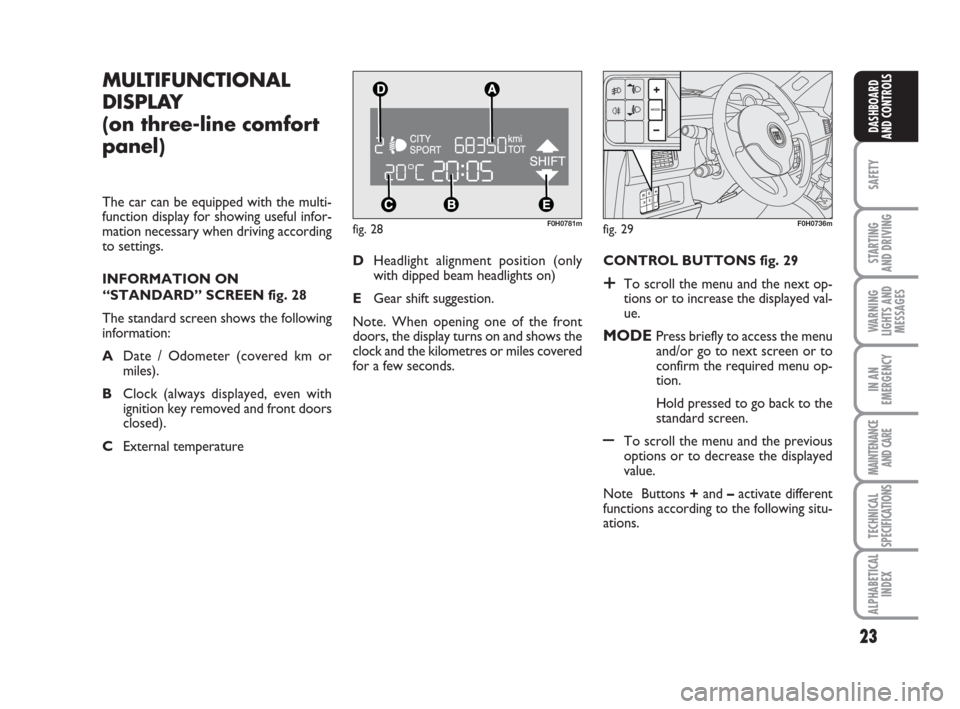
INFORMATION ON
“STANDARD” SCREEN fig. 28
The standard screen shows the following
information:
ADate / Odometer (covered km or
miles).
BClock (always displayed, even with
ignition key removed and front doors
closed).
CExternal temperature CONTROL BUTTONS fig. 29
+To scroll the menu and the next op-
tions or to increase the displayed val-
ue.
MODEPress briefly to access the menu
and/or go to next screen or to
confirm the required menu op-
tion.
Hold pressed to go back to the
standard screen.
–To scroll the menu and the previous
options or to decrease the displayed
value.
Note Buttons +and –activate different
functions according to the following situ-
ations. DHeadlight alignment position (only
with dipped beam headlights on)
EGear shift suggestion.
Note. When opening one of the front
doors, the display turns on and shows the
clock and the kilometres or miles covered
for a few seconds.
fig. 29F0H0736m
Page 36 of 210
35
SAFETY
STARTING
AND DRIVING
WARNING
LIGHTS AND
MESSAGES
IN AN
EMERGENCY
MAINTENANCE
AND CARE
TECHNICAL
SPECIFICATIONS
ALPHABETICAL
INDEX
DASHBOARD
AND CONTROLS
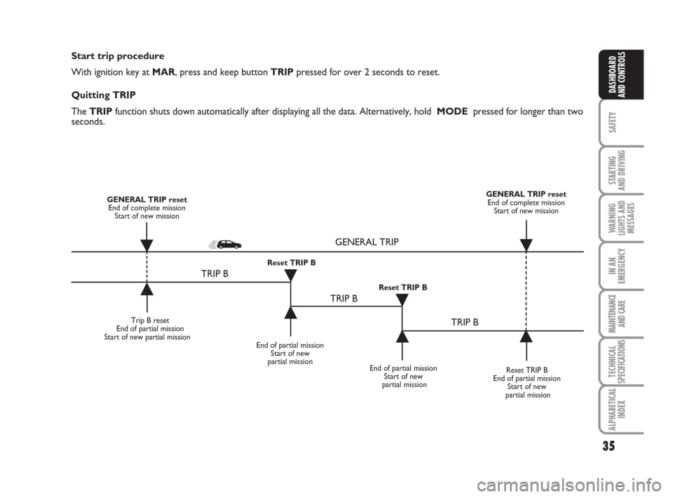
Start trip procedure
With ignition key at MAR, press and keep button TRIPpressed for over 2 seconds to reset.
Quitting TRIP
The TRIP function shuts down automatically after displaying all the data. Alternatively, hold MODE pressed for longer than two
seconds.
Trip B reset
End of partial mission
Start of new partial mission
End of partial mission
Start of new
partial mission
Reset TRIP B
End of partial mission
Start of new
partial mission GENERAL TRIP reset
End of complete mission
Start of new missionGENERAL TRIP reset
End of complete mission
Start of new mission
End of partial mission
Start of new
partial mission Reset TRIP B
Reset TRIP B
TRIP B
TRIP B
TRIP B GENERAL TRIP
˙
˙
˙
˙
˙
˙˙
˙
Page 61 of 210
60
SAFETY
STARTING
AND DRIVING
WARNING
LIGHTS AND
MESSAGES
IN AN
EMERGENCY
MAINTENANCE
AND CARE
TECHNICAL
SPECIFICATIONS
ALPHABETICAL
INDEX
DASHBOARD
AND CONTROLS
WINDOW CLEANING
WINDSCREEN WASHER/
WIPER
The device can only work when the igni-
tion key is at MAR.
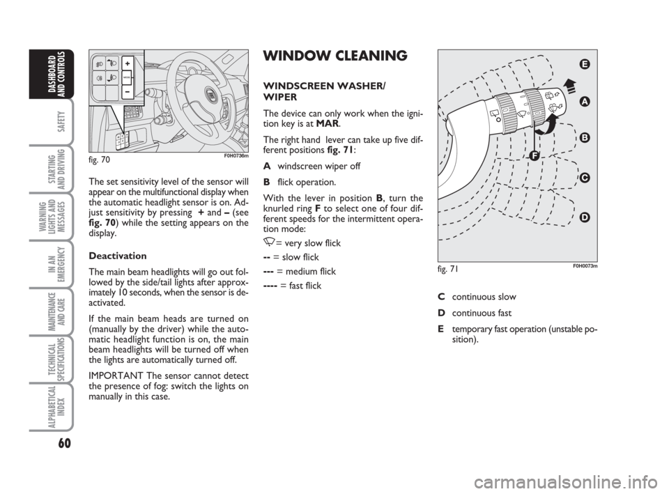
The right hand lever can take up five dif-
ferent positions fig. 71:
Awindscreen wiper off
Bflick operation.
With the lever in position B, turn the
knurled ring Fto select one of four dif-
ferent speeds for the intermittent opera-
tion mode:
,= very slow flick
--= slow flick
---= medium flick
----= fast flick The set sensitivity level of the sensor will
appear on the multifunctional display when
the automatic headlight sensor is on. Ad-
just sensitivity by pressing +and –(see
fig. 70) while the setting appears on the
display.
Deactivation
The main beam headlights will go out fol-
lowed by the side/tail lights after approx-
imately 10 seconds, when the sensor is de-
activated.
If the main beam heads are turned on
(manually by the driver) while the auto-
matic headlight function is on, the main
beam headlights will be turned off when
the lights are automatically turned off.
IMPORTANT The sensor cannot detect
the presence of fog: switch the lights on
manually in this case.
fig. 70F0H0736m
fig. 71F0H0073m
Ccontinuous slow
Dcontinuous fast
Etemporary fast operation (unstable po-
sition).
Page 63 of 210
62
SAFETY
STARTING
AND DRIVING
WARNING
LIGHTS AND
MESSAGES
IN AN
EMERGENCY
MAINTENANCE
AND CARE
TECHNICAL
SPECIFICATIONS
ALPHABETICAL
INDEX
DASHBOARD
AND CONTROLS
The wiper will flick once to indicate that
the sensor has been reactivated.
The rain sensor is able to recognize and
automatically adjust itself in the presence
of the following particular conditions:
❒dirt on the controlled surface (salt,
dirt, etc.);
❒difference between day and night.
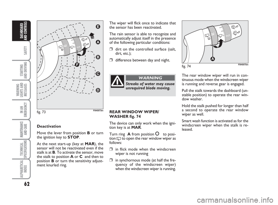
Deactivation
Move the lever from position Bor turn
the ignition key to STOP.
At the next start-up (key at MAR), the
sensor will not be reactivated even if the
stalk is at B. To activate the sensor, move
the stalk to position Aor C and then to
position Bor turn the sensitivity adjust-
ment knurled ring.
fig. 73F0H0073m
Streaks of water may cause
unrequired blade moving.
WARNINGThe rear window wiper will run in con-
tinuous mode when the windscreen wiper
is running and reverse gear is engaged.
Pull the stalk towards the dashboard (un-
stable position) to operate the rear win-
dow washer.
Hold the stalk pushed for longer than half
a second to operate the rear window
wiper as well.
Smart wash function is activated as for the
windscreen wiper when the stalk is re-
leased.
fig. 74F0H0075m
REAR WINDOW WIPER/
WASHER fig. 74
The device can only work when the igni-
tion key is at MAR.
Turn ring Afrom position
åto posi-
tion
'to open the rear window wiper as
follows:
❒in flick mode when the windscreen
wiper is not running
❒in synchornous mode (at half the fre-
quency of the windscreen wiper)
when the windscreen wiper is running.
Page 66 of 210
65
SAFETY
STARTING
AND DRIVING
WARNING
LIGHTS AND
MESSAGES
IN AN
EMERGENCY
MAINTENANCE
AND CARE
TECHNICAL
SPECIFICATIONS
ALPHABETICAL
INDEX
DASHBOARD
AND CONTROLS
fig. 77F0H0078mfig. 78F0H0079m
fig. 79F0H0254m
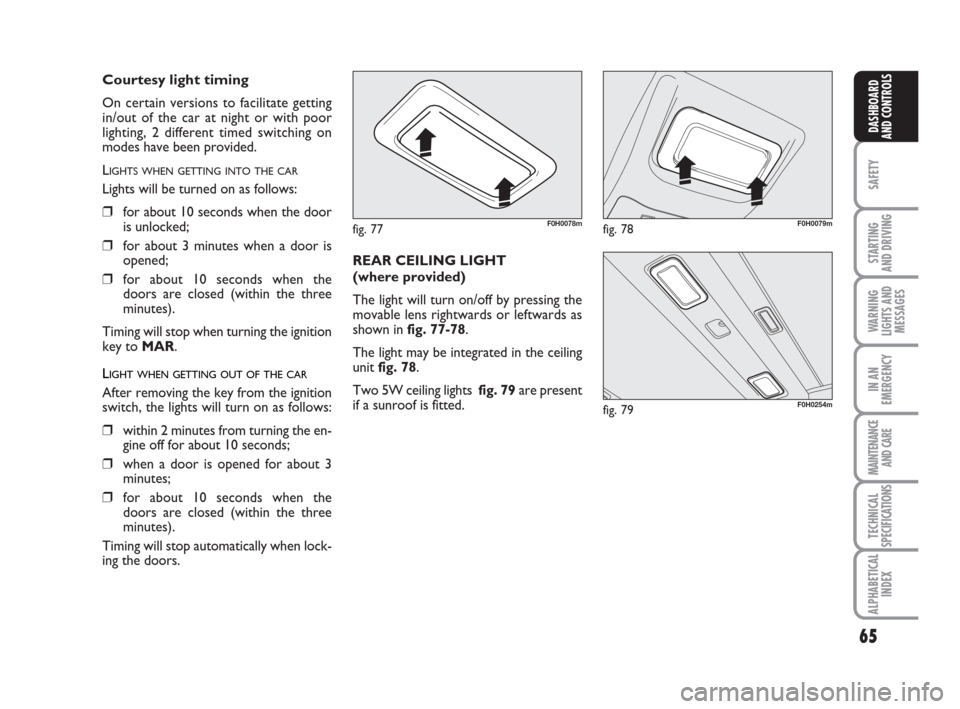
REAR CEILING LIGHT
(where provided)
The light will turn on/off by pressing the
movable lens rightwards or leftwards as
shown in fig. 77-78.
The light may be integrated in the ceiling
unit fig. 78.
Two 5W ceiling lights fig. 79are present
if a sunroof is fitted.
Courtesy light timing
On certain versions to facilitate getting
in/out of the car at night or with poor
lighting, 2 different timed switching on
modes have been provided.
L
IGHTS WHEN GETTING INTO THE CAR
Lights will be turned on as follows:
❒for about 10 seconds when the door
is unlocked;
❒for about 3 minutes when a door is
opened;
❒for about 10 seconds when the
doors are closed (within the three
minutes).
Timing will stop when turning the ignition
key to MAR.
LIGHT WHEN GETTING OUT OF THE CAR
After removing the key from the ignition
switch, the lights will turn on as follows:
❒within 2 minutes from turning the en-
gine off for about 10 seconds;
❒when a door is opened for about 3
minutes;
❒for about 10 seconds when the
doors are closed (within the three
minutes).
Timing will stop automatically when lock-
ing the doors.
Page 125 of 210
124
STARTING
AND DRIVING
IN AN
EMERGENCY
MAINTENANCE
AND CARE
TECHNICAL
SPECIFICATIONS
ALPHABETICAL
INDEX
DASHBOARD
AND
CONTROLS
SAFETY
WARNING
LIGHTS AND
MESSAGES
GENERAL WARNINGS
Lighting of a warning light is associated to
a specific message and/or buzzer when ap-
plicable. These indications are brief and
precautionary and as such must not be
considered as exhaustive and/or alterna-
tive to the information contained in the
Owner’s Handbook, which you are re-
commended to read carefully in all cases.
Refer to the information in this section in
the event of a failure indication.
IMPORTANT Failure indications on the
display fall into one of two categories: se-
riousfailure and less seriousfailure.
A warning cycle will be repeated in case
of severefailures until the case of the
problem is eliminated.
A shorter warning cycle will be run in ca-
se of less severefaults.
Press MODEto stop the warning cycle in
both cases. The warning light on the in-
strument panel will stay on until the cau-
se of the failure is eliminated.LOW BRAKE FLUID
LEVEL (red)
HANDBRAKE ON (red)
When the ignition key is moved to MAR,
the warning light turns on and should go
off after a few seconds.
Low brake fluid level
The warning light comes on when the le-
vel of the brake fluid in the reservoir falls
below the minimum level due to possible
leaks in the circuit.
The display will show the dedicated mes-
sage.
x
Handbrake on
The warning light turns on when the hand-
brake is on.
On certain versions, if the car is moving
the buzzer will also sound.
IMPORTANT If the warning light turns on
when travelling, check that the handbrake
is not engaged.
AIRBAG FAILURE (red)
When the ignition key is mo-
ved to MAR, the warning light
turns on and should go off after
a few seconds.
The warning light stays on steady if there
is a failure in the airbag system.
The display will show the dedicated mes-
sage.¬
If the warning light xturns
on when travelling (with the
message on the display) stop the car
immediately and contact Fiat Dea-
lership.
WARNING
Page 183 of 210
182
STARTING
AND DRIVING
MAINTENANCE
AND CARE
ALPHABETICAL
INDEX
DASHBOARD
AND
CONTROLS
SAFETY
WARNING
LIGHTS AND
MESSAGES
TECHNICAL
SPECIFICATIONS
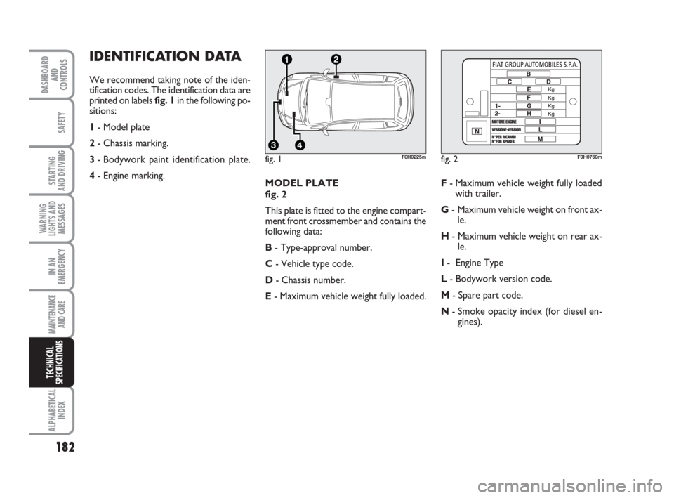
IDENTIFICATION DATA
We recommend taking note of the iden-
tification codes. The identification data are
printed on labels fig. 1in the following po-
sitions:
1- Model plate
2- Chassis marking.
3- Bodywork paint identification plate.
4- Engine marking.
MODEL PLATE
fig. 2
This plate is fitted to the engine compart-
ment front crossmember and contains the
following data:
B- Type-approval number.
C- Vehicle type code.
D- Chassis number.
E- Maximum vehicle weight fully loaded.F- Maximum vehicle weight fully loaded
with trailer.
G- Maximum vehicle weight on front ax-
le.
H- Maximum vehicle weight on rear ax-
le.
I- Engine Type
L- Bodywork version code.
M- Spare part code.
N- Smoke opacity index (for diesel en-
gines).
fig. 1
4
21
3
F0H0225mfig. 2F0H0760m
IN AN
EMERGENCY