buttons FIAT IDEA 2009 1.G Owners Manual
[x] Cancel search | Manufacturer: FIAT, Model Year: 2009, Model line: IDEA, Model: FIAT IDEA 2009 1.GPages: 210, PDF Size: 3.62 MB
Page 6 of 210
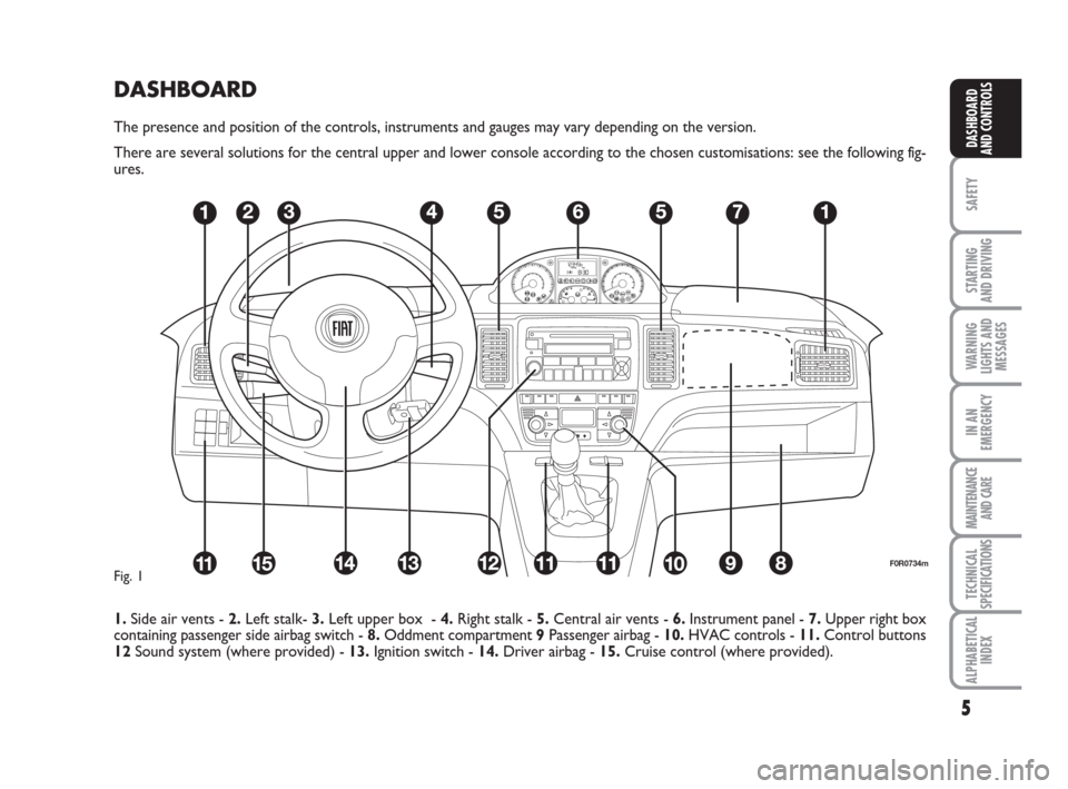
DASHBOARD
The presence and position of the controls, instruments and gauges may vary depending on the version.
There are several solutions for the central upper and lower console according to the chosen customisations: see the following fig-
ures.
1.Side air vents - 2.Left stalk- 3.Left upper box - 4.Right stalk - 5.Central air vents - 6.Instrument panel - 7.Upper right box
containing passenger side airbag switch - 8.Oddment compartment 9Passenger airbag - 10.HVAC controls - 11.Control buttons
12Sound system (where provided) - 13.Ignition switch - 14.Driver airbag - 15.Cruise control (where provided).
5
SAFETY
STARTING
AND DRIVING
WARNING
LIGHTS AND
MESSAGES
IN AN
EMERGENCY
MAINTENANCE
AND CARE
TECHNICAL
SPECIFICATIONS
ALPHABETICAL
INDEX
DASHBOARD
AND CONTROLS
F0R0734mFig. 1
Page 14 of 210
13
SAFETY
STARTING
AND DRIVING
WARNING
LIGHTS AND
MESSAGES
IN AN
EMERGENCY
MAINTENANCE
AND CARE
TECHNICAL
SPECIFICATIONS
ALPHABETICAL
INDEX
DASHBOARD
AND CONTROLS
Opening the tailgate with the
remote control
Hold button
Rpressed to unlock
(open) the tailgate. The direction indica-
tors will blink twice when the tailgate is
opened.
IMPORTANT Powerful radio transmis-
sions not related to the car (e.g. mobile
phones, amateur radios, etc.) may inter-
fere with the frequency of the remote
control. Remote control operation may
be impaired.
Electrical closure from inside
fig. 14
With the doors closed, press button Aon
the central dashboard to lock (LED on) or
unlock (LED off) the doors.
IMPORTANT If the door is not correct-
ly closed or if a fault is present in the sys-
tem, the door locking device from inside
the car will not work.
The device will resume normal operation
after removing the cause of the fault.Only the doors used to get
out of the car will be un-
locked if the door lock button
inside the car is pressed by
mistake. The tailgate will remain
locked. Press the lock/unlock buttons
to realign the system.
fig. 15aF0H0704m
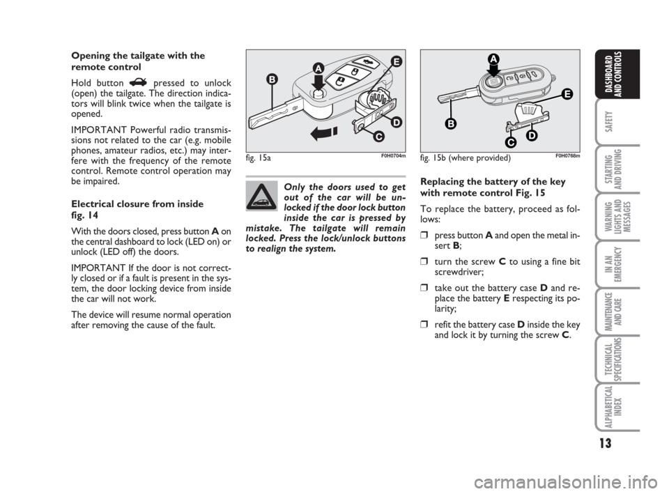
Replacing the battery of the key
with remote control Fig. 15
To replace the battery, proceed as fol-
lows:
❒press button Aand open the metal in-
sert B;
❒turn the screw Cto using a fine bit
screwdriver;
❒take out the battery case Dand re-
place the battery Erespecting its po-
larity;
❒refit the battery case Dinside the key
and lock it by turning the screw C.
fig. 15b (where provided)F0H0768m
Page 22 of 210
21
SAFETY
STARTING
AND DRIVING
WARNING
LIGHTS AND
MESSAGES
IN AN
EMERGENCY
MAINTENANCE
AND CARE
TECHNICAL
SPECIFICATIONS
ALPHABETICAL
INDEX
DASHBOARD
AND CONTROLS
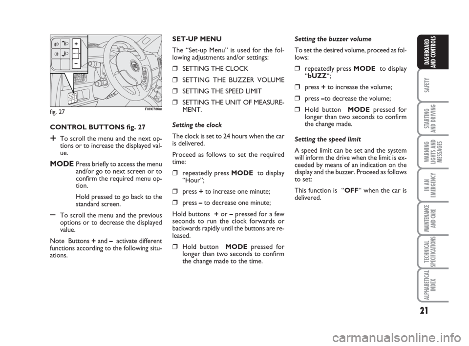
CONTROL BUTTONS fig. 27
+To scroll the menu and the next op-
tions or to increase the displayed val-
ue.
MODEPress briefly to access the menu
and/or go to next screen or to
confirm the required menu op-
tion.
Hold pressed to go back to the
standard screen.
–To scroll the menu and the previous
options or to decrease the displayed
value.
Note Buttons +and –activate different
functions according to the following situ-
ations.Setting the buzzer volume
To set the desired volume, proceed as fol-
lows:
❒repeatedly press MODE to display
“bUZZ“;
❒press +to increase the volume;
❒press –to decrease the volume;
❒Hold button MODEpressed for
longer than two seconds to confirm
the change made.
Setting the speed limit
A speed limit can be set and the system
will inform the drive when the limit is ex-
ceeded by means of an indication on the
display and the buzzer. Proceed as follows
to set:
This function is “OFF“ when the car is
delivered. SET-UP MENU
The “Set-up Menu” is used for the fol-
lowing adjustments and/or settings:
❒SETTING THE CLOCK
❒SETTING THE BUZZER VOLUME
❒SETTING THE SPEED LIMIT
❒SETTING THE UNIT OF MEASURE-
MENT.
Setting the clock
The clock is set to 24 hours when the car
is delivered.
Proceed as follows to set the required
time:
❒repeatedly press MODE to display
“Hour”;
❒press +to increase one minute;
❒press –to decrease one minute;
Hold buttons +or –pressed for a few
seconds to run the clock forwards or
backwards rapidly until the buttons are re-
leased.
❒Hold button MODEpressed for
longer than two seconds to confirm
the change made to the time.
fig. 27F0H0736m
Page 24 of 210
23
SAFETY
STARTING
AND DRIVING
WARNING
LIGHTS AND
MESSAGES
IN AN
EMERGENCY
MAINTENANCE
AND CARE
TECHNICAL
SPECIFICATIONS
ALPHABETICAL
INDEX
DASHBOARD
AND CONTROLS
fig. 28F0H0781m
MULTIFUNCTIONAL
DISPLAY
(on three-line comfort
panel)
The car can be equipped with the multi-
function display for showing useful infor-
mation necessary when driving according
to settings.
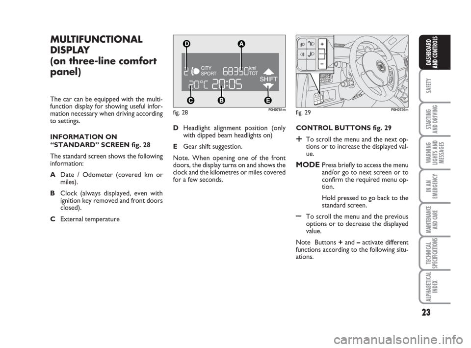
INFORMATION ON
“STANDARD” SCREEN fig. 28
The standard screen shows the following
information:
ADate / Odometer (covered km or
miles).
BClock (always displayed, even with
ignition key removed and front doors
closed).
CExternal temperature CONTROL BUTTONS fig. 29
+To scroll the menu and the next op-
tions or to increase the displayed val-
ue.
MODEPress briefly to access the menu
and/or go to next screen or to
confirm the required menu op-
tion.
Hold pressed to go back to the
standard screen.
–To scroll the menu and the previous
options or to decrease the displayed
value.
Note Buttons +and –activate different
functions according to the following situ-
ations. DHeadlight alignment position (only
with dipped beam headlights on)
EGear shift suggestion.
Note. When opening one of the front
doors, the display turns on and shows the
clock and the kilometres or miles covered
for a few seconds.
fig. 29F0H0736m
Page 25 of 210
24
SAFETY
STARTING
AND DRIVING
WARNING
LIGHTS AND
MESSAGES
IN AN
EMERGENCY
MAINTENANCE
AND CARE
TECHNICAL
SPECIFICATIONS
ALPHABETICAL
INDEX
DASHBOARD
AND CONTROLS
Headlight adjustment (only
with dipped beam headlights on)
– when the standard page is displayed, this
is used to adjust the headlights (see the
“Headlights” paragraph in this chapter).
Setup menu
– for scrolling the menu up and down;
– to increase or decrease values during
settings.
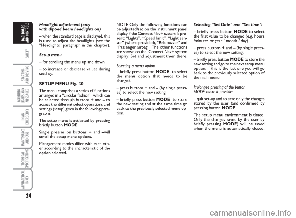
SETUP MENU Fig. 30
The menu comprises a series of functions
arranged in a “circular fashion” which can
be selected through buttons +and –to
access the different select operations and
settings (setup) given in the following para-
graphs.
The setup menu is activated by pressing
briefly button MODE.
Single presses on buttons +and –will
scroll the setup menu options.
Management modes differ with each oth-
er according to the characteristic of the
option selected.Selecting “Set Date” and “Set time”:
– briefly press button MODEto select
the first value to be changed (e.g. hours
/minutes or year / month / day).
– press buttons +and –(by single press-
es) to select the new setting;
– briefly press button MODEto store the
new setting and go to the next setup menu
option: if this is the last one you will go
back to the previously selected option of
the main menu.
Prolonged pressing of the button
MODE make it possible:
– quit set-up and to save only the changes
stored by the user (and confirmed by
pressing button MODE).
The setup menu environment is timed.
Only the changes saved by the user by
briefly pressing MODE) will be saved
when the menu is automatically closed. NOTE Only the following functions can
be adjusted/set on the instrument panel
display if the Connect Nav+ system is pre-
sent: “Lights”, “Speed limit”, “Light sen-
sor” (where provided), “Belt buzzer” and
“Passenger airbag”. The other functions
are shown on the Connect Nav+ system
display. Set and adjustment them there.
Selecting a menu option
– briefly press button MODEto select
the menu option that needs to be
changed.
– press buttons +and –(by single press-
es) to select the new setting;
– briefly press button MODEto store
the new setting and at the same time go
back to the previously selected menu op-
tion.
Page 27 of 210
26
SAFETY
STARTING
AND DRIVING
WARNING
LIGHTS AND
MESSAGES
IN AN
EMERGENCY
MAINTENANCE
AND CARE
TECHNICAL
SPECIFICATIONS
ALPHABETICAL
INDEX
DASHBOARD
AND CONTROLS
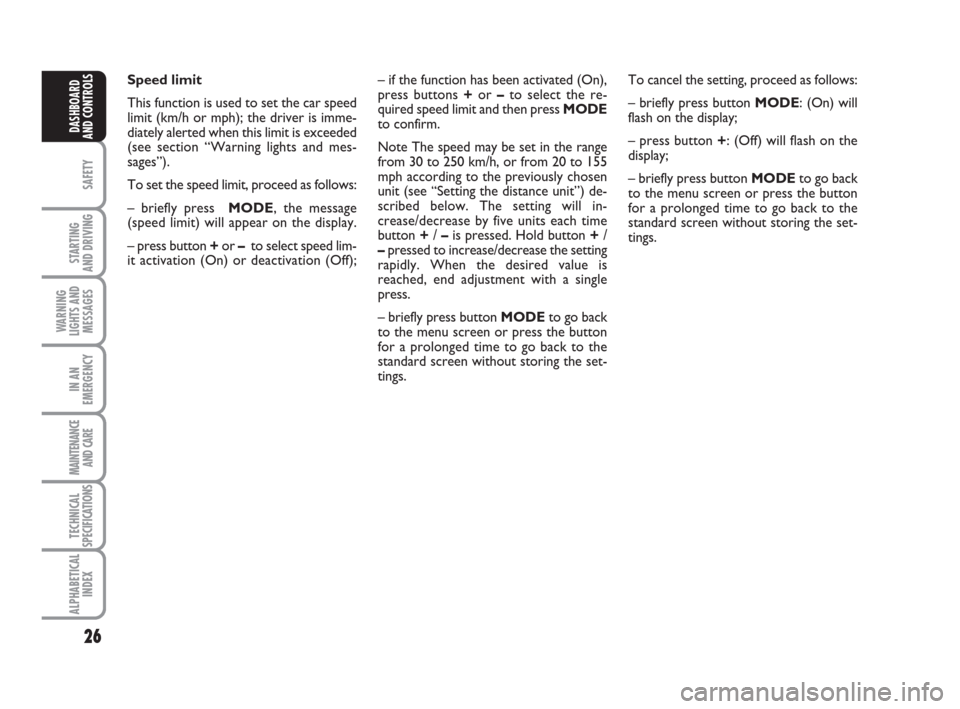
Speed limit
This function is used to set the car speed
limit (km/h or mph); the driver is imme-
diately alerted when this limit is exceeded
(see section “Warning lights and mes-
sages”).
To set the speed limit, proceed as follows:
– briefly press MODE, the message
(speed limit) will appear on the display.
– press button +or –to select speed lim-
it activation (On) or deactivation (Off);To cancel the setting, proceed as follows:
– briefly press button MODE: (On) will
flash on the display;
– press button +: (Off) will flash on the
display;
– briefly press button MODEto go back
to the menu screen or press the button
for a prolonged time to go back to the
standard screen without storing the set-
tings. – if the function has been activated (On),
press buttons +or –to select the re-
quired speed limit and then press MODE
to confirm.
Note The speed may be set in the range
from 30 to 250 km/h, or from 20 to 155
mph according to the previously chosen
unit (see “Setting the distance unit”) de-
scribed below. The setting will in-
crease/decrease by five units each time
button +/ –is pressed. Hold button +/
–pressed to increase/decrease the setting
rapidly. When the desired value is
reached, end adjustment with a single
press.
– briefly press button MODEto go back
to the menu screen or press the button
for a prolonged time to go back to the
standard screen without storing the set-
tings.
Page 32 of 210
31
SAFETY
STARTING
AND DRIVING
WARNING
LIGHTS AND
MESSAGES
IN AN
EMERGENCY
MAINTENANCE
AND CARE
TECHNICAL
SPECIFICATIONS
ALPHABETICAL
INDEX
DASHBOARD
AND CONTROLS
Adjust the button volume
(Button Vol.)
This function is used to set the volume of
the roger-beep accompanying the activa-
tion of buttons MODE, +e –through 8
levels.
To set the desired volume, proceed as fol-
lows:
– briefly press button MODE: the previ-
ously set volume “level” starts flashing on
the display;
– press button +or –to set;
– briefly press button MODEto go back
to the menu screen or press the button
for a prolonged time to go back to the
standard screen without storing the set-
tings.
S.B.R. buzzer reactivation (Belt
Buzzer) (where provided)
This function can be only displayed after a
Fiat Dealership has deactivated the S.B.R.
system (see paragraph “S.B.R. system” in
section “Safety devices”).The indications will appear more fre-
quently where there are 200 km left. For
1.3 Multijet versions, refer to the “Service
Schedule” in the “Maintenance and care”
chapter for replacing the air cleaner, the
engine oil and the engine oil filter. The in-
dication will appear in kilometres or miles
according to the settings. When the next
scheduled service operation is approach-
ing, the message “Service” will appear on
the display followed by the number of kilo-
metres or miles left when the key is
turned to MAR. The “Service Schedule”
information is provided with kilometres
(km)/miles (mi) or days (dd), according to
the deadline which appears first. Go to a
Fiat Dealership where the “Scheduled Ser-
vice” operations will be performed and the
message will be reset. Scheduled Servicing (Service)
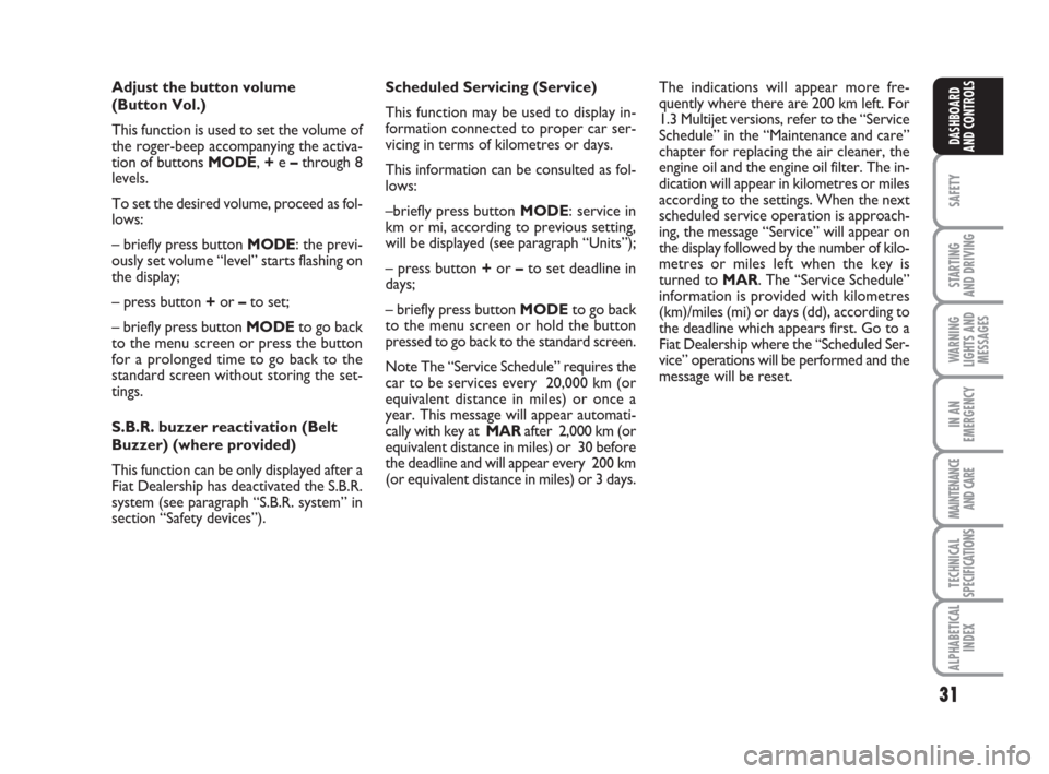
This function may be used to display in-
formation connected to proper car ser-
vicing in terms of kilometres or days.
This information can be consulted as fol-
lows:
–briefly press button MODE: service in
km or mi, according to previous setting,
will be displayed (see paragraph “Units”);
– press button +or –to set deadline in
days;
– briefly press button MODEto go back
to the menu screen or hold the button
pressed to go back to the standard screen.
Note The “Service Schedule” requires the
car to be services every 20,000 km (or
equivalent distance in miles) or once a
year. This message will appear automati-
cally with key at MARafter 2,000 km (or
equivalent distance in miles) or 30 before
the deadline and will appear every 200 km
(or equivalent distance in miles) or 3 days.
Page 33 of 210
32
SAFETY
STARTING
AND DRIVING
WARNING
LIGHTS AND
MESSAGES
IN AN
EMERGENCY
MAINTENANCE
AND CARE
TECHNICAL
SPECIFICATIONS
ALPHABETICAL
INDEX
DASHBOARD
AND CONTROLS
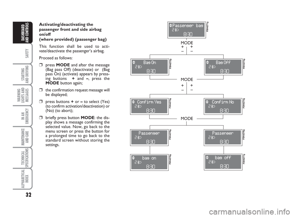
Activating/deactivating the
passenger front and side airbag
on/off
(where provided) (passenger bag)
This function shall be used to acti-
vate/deactivate the passenger’s airbag.
Proceed as follows:
❒press MODEand after the message
(Bag pass Off) (deactivate) or (Bag
pass On) (activate) appears by press-
ing buttons +and –, press the
MODEbutton again;
❒the confirmation request message will
be displayed;
❒press buttons +or –to select (Yes)
(to confirm activation/deactivation) or
(No) (to abort);
❒briefly press button MODE: the dis-
play shows a message confirming the
selected value. Now, go back to the
menu screen or press the button for
a prolonged time to go back to the
standard screen without storing the
settings.
MODE
MODE
MODE
– +
F0H4271g F0H4272g
F0H4273g F0H4275g
F0H4274g F0H4276gF0H4276g
F0H4278gF0H4277g
– +
– +
– +
Page 39 of 210
38
SAFETY
STARTING
AND DRIVING
WARNING
LIGHTS AND
MESSAGES
IN AN
EMERGENCY
MAINTENANCE
AND CARE
TECHNICAL
SPECIFICATIONS
ALPHABETICAL
INDEX
DASHBOARD
AND CONTROLS
fig. 38F0H0046m
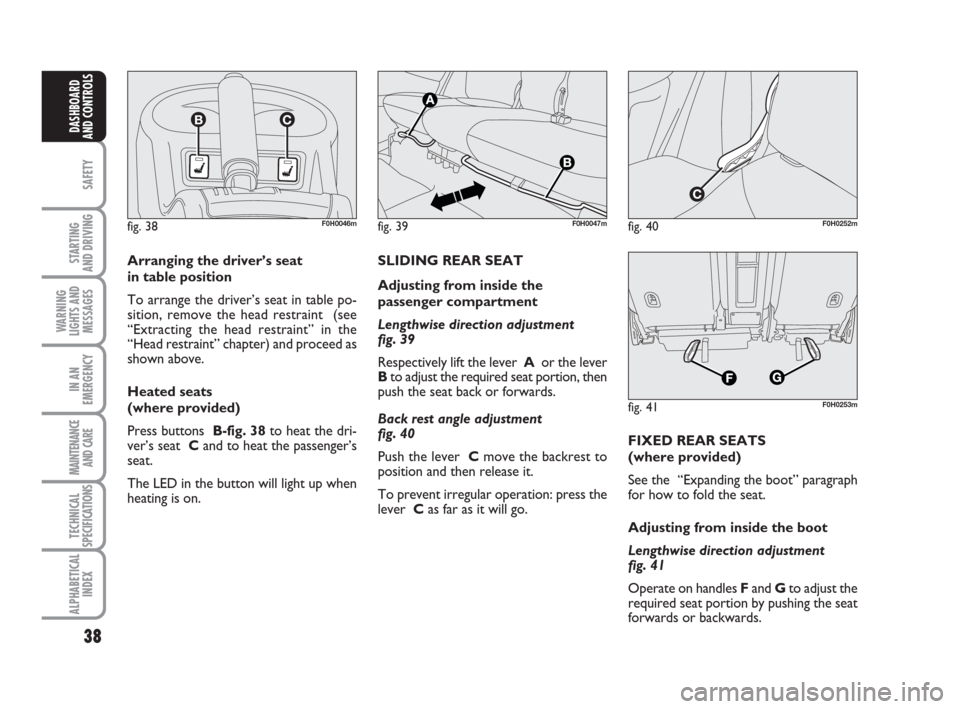
Arranging the driver’s seat
in table position
To arrange the driver’s seat in table po-
sition, remove the head restraint (see
“Extracting the head restraint” in the
“Head restraint” chapter) and proceed as
shown above.
Heated seats
(where provided)
Press buttons B-fig. 38to heat the dri-
ver’s seat Cand to heat the passenger’s
seat.
The LED in the button will light up when
heating is on.SLIDING REAR SEAT
Adjusting from inside the
passenger compartment
Lengthwise direction adjustment
fig. 39
Respectively lift the lever Aor the lever
Bto adjust the required seat portion, then
push the seat back or forwards.
Back rest angle adjustment
fig. 40
Push the lever Cmove the backrest to
position and then release it.
To prevent irregular operation: press the
lever Cas far as it will go.
fig. 39F0H0047mfig. 40F0H0252m
fig. 41F0H0253m
FIXED REAR SEATS
(where provided)
See the “Expanding the boot” paragraph
for how to fold the seat.
Adjusting from inside the boot
Lengthwise direction adjustment
fig. 41
Operate on handles Fand Gto adjust the
required seat portion by pushing the seat
forwards or backwards.
Page 53 of 210
52
SAFETY
STARTING
AND DRIVING
WARNING
LIGHTS AND
MESSAGES
IN AN
EMERGENCY
MAINTENANCE
AND CARE
TECHNICAL
SPECIFICATIONS
ALPHABETICAL
INDEX
DASHBOARD
AND CONTROLS
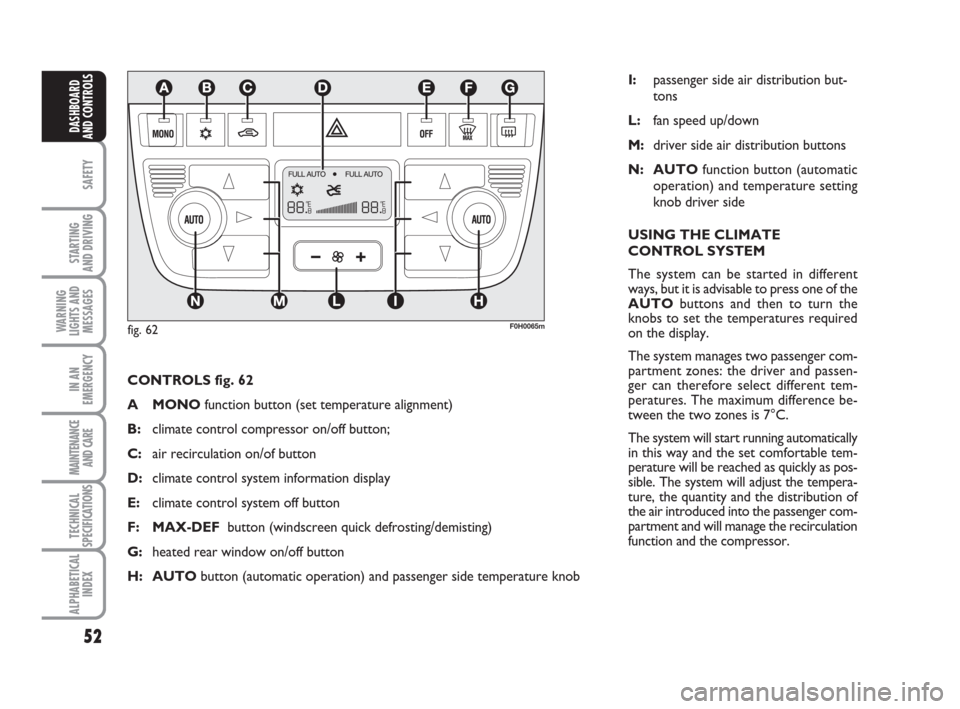
CONTROLS fig. 62
A MONOfunction button (set temperature alignment)
B:climate control compressor on/off button;
C: air recirculation on/of button
D:climate control system information display
E:climate control system off button
F: MAX-DEFbutton (windscreen quick defrosting/demisting)
G:heated rear window on/off button
H: AUTObutton (automatic operation) and passenger side temperature knob
F0H0065m
I:passenger side air distribution but-
tons
L:fan speed up/down
M:driver side air distribution buttons
N: AUTOfunction button (automatic
operation) and temperature setting
knob driver side
USING THE CLIMATE
CONTROL SYSTEM
The system can be started in different
ways, but it is advisable to press one of the
AUTObuttons and then to turn the
knobs to set the temperatures required
on the display.
The system manages two passenger com-
partment zones: the driver and passen-
ger can therefore select different tem-
peratures. The maximum difference be-
tween the two zones is 7°C.
The system will start running automatically
in this way and the set comfortable tem-
perature will be reached as quickly as pos-
sible. The system will adjust the tempera-
ture, the quantity and the distribution of
the air introduced into the passenger com-
partment and will manage the recirculation
function and the compressor.
fig. 62