buttons FIAT IDEA 2010 1.G User Guide
[x] Cancel search | Manufacturer: FIAT, Model Year: 2010, Model line: IDEA, Model: FIAT IDEA 2010 1.GPages: 210, PDF Size: 4.4 MB
Page 54 of 210
53
SAFETY
STARTING
AND DRIVING
WARNING
LIGHTS AND
MESSAGES
IN AN
EMERGENCY
MAINTENANCE
AND CARE
TECHNICAL
SPECIFICATIONS
ALPHABETICAL
INDEX
DASHBOARD
AND CONTROLS
Manual intervention is only required for
the following functions during fully auto-
matic operation.
❒MONOto uniform the temperature
and the air distribution on front pas-
senger or rear passenger zones to the
driver’s zone;
❒…air recirculation, to keep it always
on or off;
❒-to speed up demisting/defrosting of
windscreen, side windows, rear window
and door mirrors;
❒(to demist/defrost the heated rear
window and the external rearview
mirrors.
During completely automatic system op-
eration, you can vary the set temperature,
the air distribution and the fan speed us-
ing the corresponding buttons or knobs
at any time: the system will automatically
change settings to adapt to the new re-
quest.
During fully automatic operation (FULL
AUTO), the word FULLwill dissapear
if the air distribution, air speed, compres-
sor and/or recirculation settings are
changed. In this way, the functions will
switch from automatic to manual control until AUTOis pressed again. The fan
speed is the same in all the zones of the
passenger compartment.
With on or more manually set functions,
the introduced air temperature is still
managed automatically by the system, ex-
cept for when the compressor is off: in the
case, the air introduced into the passen-
ger compartment cannot be cooler than
the outside air.
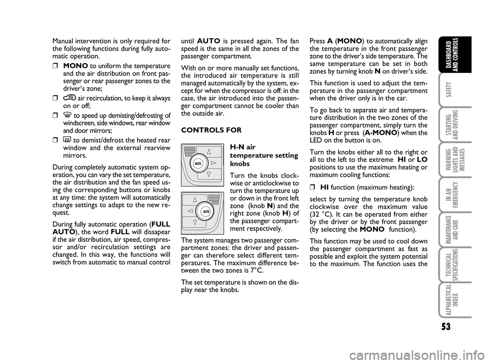
CONTROLS FOR
H-N air
temperature setting
knobs
Turn the knobs clock-
wise or anticlockwise to
turn the temperature up
or down in the front left
zone (knob N) and the
right zone (knob H) of
the passenger compart-
ment respectively.
The system manages two passenger com-
partment zones: the driver and passen-
ger can therefore select different tem-
peratures. The maximum difference be-
tween the two zones is 7°C.
The set temperature is shown on the dis-
play near the knobs.Press A(MONO) to automatically align
the temperature in the front passenger
zone to the driver’s side temperature. The
same temperature can be set in both
zones by turning knob N on driver’s side.
This function is used to adjust the tem-
perature in the passenger compartment
when the driver only is in the car.
To go back to separate air and tempera-
ture distribution in the two zones of the
passenger compartment, simply turn the
knobs H or press (A-MONO) when the
LED on the button is on.
Turn the knobs either all to the right or
all to the left to the extreme HIor LO
positions to use the maximum heating or
maximum cooling functions:
❒HIfunction (maximum heating):
select by turning the temperature knob
clockwise over the maximum value
(32 °C). It can be operated from either
by the driver or by the front passenger
(by selecting the MONOfunction).
This function may be used to cool down
the passenger compartment as fast as
possible and exploit the system potential
to the maximum. The function uses the
036-092 LUM IDEA GB 2 ed.qxd 14-01-2010 12:14 Pagina 53
Page 55 of 210
54
SAFETY
STARTING
AND DRIVING
WARNING
LIGHTS AND
MESSAGES
IN AN
EMERGENCY
MAINTENANCE
AND CARE
TECHNICAL
SPECIFICATIONS
ALPHABETICAL
INDEX
DASHBOARD
AND CONTROLS
maximum coolant temperature while air
and fan speed distribution are managed
by the system according to conditions.
Specifically, if the heating fluid is not
warm enough, the fan will not start up at
the maximum speed immediately to limit
introducing excessively cool air into the
passenger compartment.
All manual settings will be allowed when
this function is on.
To switch the function off, simply turn
the temperature knob anticlockwise and
set the required temperature.
❒LOfunction (maximum cooling):
select by turning the temperature knob
anticlockwise beyond the minimum
value (16 °C). It can be operated from
either by the driver or by the front pas-
senger (by selecting the MONOfunc-
tion).
This function may be used to cool down
the passenger compartment as fast as
possible and exploit the system potential
to the maximum. The function activates
air recirculation and the climate control
compressor, air distribution and fan
speed are managed by the system
according to environmental conditions. All manual settings will be allowed when
this function is on.
To switch the function off, simply turn
the temperature knob clockwise and set
the required temperature.
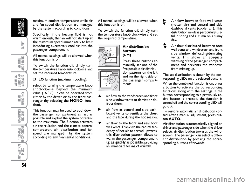
Air distribution
buttons
(I-M)
Press these buttons to
manually set one of the
five possible air distribu-
tion patterns on the left
and on the right side of
the passenger compart-
ment:
▲air flow to the windscreen and front
side window vents to demist or de-
frost them;
˙air flow at central and side dash-
board vents to ventilate the chest
and the face during the hot season;
▼air flow to the front and rear foot
well vents. Thanks to the natural ten-
dency of hot air to spread upwards,
this distribution pattern allows to
warm the passenger compartment
up as quickly as possible, providing
an immediate feeling of warmth.
˙
▼Air flow between foot well vents
(hotter air) and central and side
dashboard vents (cooler air). This
distribution mode is particularly use-
ful in spring and autumn on a sunny
day.
▲
▼Air flow distributed between foot
well vents and windscreen and front
side window defrosting/demisting
vents. This allows an adequate
warming of the passenger compart-
ment and prevents the windows
from misting up.
The set distribution is shown by the cor-
responding LEDs on the selected buttons.
When the combined function is on, press
a button to activate the corresponding
functions along with the settings. If the
button corresponding to a previously ac-
tive button is pressed, the function is
turned off and the corresponding LED will
go out.
To restore automatic air distribution con-
trol after a manual adjustment, press but-
ton AUTO.
Air distribution is automatically aligned on
driver and passenger side when the driver
selects air distribution towards the wind-
screen. The passenger can select a differ-
ent distribution by pressing the corre-
sponding buttons afterwards.
036-092 LUM IDEA GB 2 ed.qxd 14-01-2010 12:14 Pagina 54
Page 56 of 210
55
SAFETY
STARTING
AND DRIVING
WARNING
LIGHTS AND
MESSAGES
IN AN
EMERGENCY
MAINTENANCE
AND CARE
TECHNICAL
SPECIFICATIONS
ALPHABETICAL
INDEX
DASHBOARD
AND CONTROLS
Fan speed
adjustment buttons
(L)
Press button pto
increase or to decrease
the fan speed and
therefore the amount of air admitted
into the passenger compartment,
although keeping the required tempera-
ture set.
The fan speed is shown by the lit bars on
the display:
❒Max. fan speed = all bars lit;
❒min fan speed = one bar lit.
The fan can be cut off only if the climate
control compressor has been switched
off pressing button B.
IMPORTANT To restore automatic fan
speed control after a manual adjustment,
press button AUTO.AUTO
(H-N)
buttons (automatic
operation)
Press AUTOdriver’s
side and/or passenger’s
side to automatically ad-
just the air speed and air
distribution in the cor-
responding zones can-
celling al previous manu-
al settings.
The message FULL AUTOwill appear
on the front display in this condition.
By manually intervening on at least of the
functions automatically managed by the
system (air recirculation, fan speed or
compressor on/off), the word FULL will
disappear from the display indicating that
the system is no longer automatically con-
trolling all the functions (the temperature
will still be controlled automatically by the
system).
IMPORTANT Should the system (after
manual settings) be no longer able to guar-
antee the required temperature set in the
passenger compartment, the set tempera-
ture value will start flashing to indicate this
condition, after one minute the AUTO
message will turn off.To restore system automatic control at
any time, after one or more manual ad-
justments, press button AUTO.
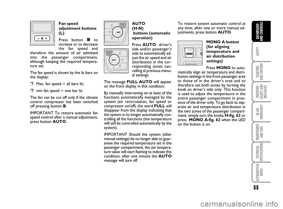
MONO A button
(for aligning
temperature and
air distribution
settings)
Press MONOto auto-
matically align air temperature and distri-
bution settings in the front passenger area
to those of in the driver’s area and to
therefore set both zones by turning the
knob on driver’s side only. This function
is used to adjust the temperature in the
entire passenger compartment in pres-
ence of the driver only. To go back to sep-
arate air and temperature distribution in
the two zones of the passenger compart-
ment, simply turn the knobs H-fig. 62or
press MONO A-fig. 62when the LED
on the button is on.
036-092 LUM IDEA GB 2 ed.qxd 14-01-2010 12:14 Pagina 55
Page 69 of 210
68
SAFETY
STARTING
AND DRIVING
WARNING
LIGHTS AND
MESSAGES
IN AN
EMERGENCY
MAINTENANCE
AND CARE
TECHNICAL
SPECIFICATIONS
ALPHABETICAL
INDEX
DASHBOARD
AND CONTROLS
INTERIOR EQUIPMENT
UPPER ODDMENT
COMPARTMENTS
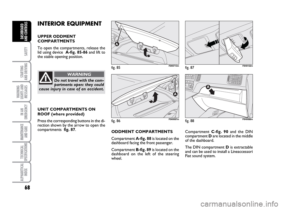
To open the compartments, release the
lid using device A-fig. 85-86 and lift to
the stable opening position.
UNIT COMPARTMENTS ON
ROOF (where provided)
Press the corresponding buttons in the di-
rection shown by the arrow to open the
compartments fig. 87.
fig. 85F0H0713m
fig. 86F0H0087m
fig. 87F0H0152m
Do not travel with the com-
partments open: they could
cause injury in case of an accident.
WARNING
Compartment C-fig. 90and the DIN
compartment Dare located in the middle
of the dashboard.
The DIN compartment Dis extractable
and can be used to install a Lineaccessori
Fiat sound system.
fig. 88F0H0088m
ODDMENT COMPARTMENTS
Compartment A-fig. 88is located on the
dashboard facing the front passenger.
Compartment B-fig. 89is located on the
dashboard on the left of the steering
wheel.
036-092 LUM IDEA GB 2 ed.qxd 14-01-2010 12:15 Pagina 68
Page 75 of 210
74
SAFETY
STARTING
AND DRIVING
WARNING
LIGHTS AND
MESSAGES
IN AN
EMERGENCY
MAINTENANCE
AND CARE
TECHNICAL
SPECIFICATIONS
ALPHABETICAL
INDEX
DASHBOARD
AND CONTROLS
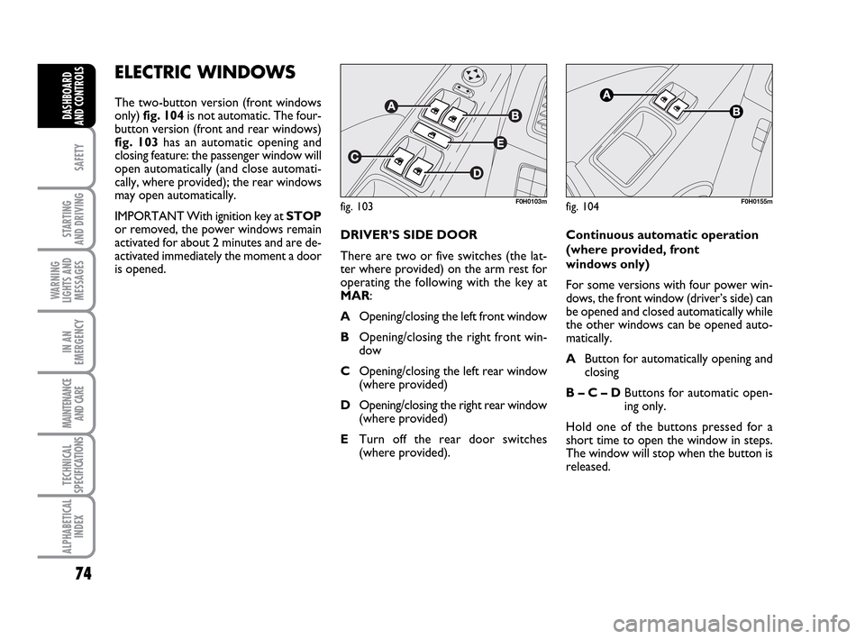
ELECTRIC WINDOWS
The two-button version (front windows
only) fig. 104 is not automatic. The four-
button version (front and rear windows)
fig. 103 has an automatic opening and
closing feature: the passenger window will
open automatically (and close automati-
cally, where provided); the rear windows
may open automatically.
IMPORTANT With ignition key at STOP
or removed, the power windows remain
activated for about 2 minutes and are de-
activated immediately the moment a door
is opened.
fig. 103F0H0103mfig. 104F0H0155m
DRIVER’S SIDE DOOR
There are two or five switches (the lat-
ter where provided) on the arm rest for
operating the following with the key at
MAR:
AOpening/closing the left front window
BOpening/closing the right front win-
dow
COpening/closing the left rear window
(where provided)
DOpening/closing the right rear window
(where provided)
ETurn off the rear door switches
(where provided).Continuous automatic operation
(where provided, front
windows only)
For some versions with four power win-
dows, the front window (driver’s side) can
be opened and closed automatically while
the other windows can be opened auto-
matically.
AButton for automatically opening and
closing
B – C – DButtons for automatic open-
ing only.
Hold one of the buttons pressed for a
short time to open the window in steps.
The window will stop when the button is
released.
036-092 LUM IDEA GB 2 ed.qxd 14-01-2010 12:15 Pagina 74
Page 83 of 210
82
SAFETY
STARTING
AND DRIVING
WARNING
LIGHTS AND
MESSAGES
IN AN
EMERGENCY
MAINTENANCE
AND CARE
TECHNICAL
SPECIFICATIONS
ALPHABETICAL
INDEX
DASHBOARD
AND CONTROLS
HEADLIGHTS
BEAM DIRECTION
Correct direction of the headlights is es-
sential for the comfort and safety of the
driver and the other road users. The head-
lights must be correctly directed to ensure
the best visibility conditions when the
headlights are on. Contact a Fiat Dealer-
ship to have the headlights properly ad-
justed.
HEADLIGHT CORRECTOR
This device works with the key at MAR
and the dipped beam headlights on. The
car will slant backwards when it is loaded,
raising the light beam. The beams must
therefore be directed again in this case.
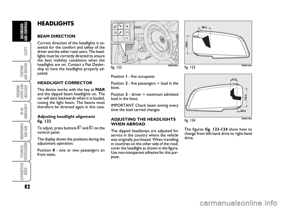
Adjusting headlight alignment
fig. 122
To adjust, press buttons
and Òon the
control panel.
The display shows the positions during the
adjustment operation.
Position 0- one or two passengers on
front seats.
fig. 122F0H0756m
Position 1- five occupants
Position 2- five passengers + load in the
boot.
Position 3- driver + maximum admitted
load in the boot.
IMPORTANT Check beam aiming every
time the load carried changes.
ADJUSTING THE HEADLIGHTS
WHEN ABROAD
The dipped headlamps are adjusted for
service in the country where the vehicle
was originally purchased. When travelling
in countries on the other side of the road,
cover the headlight as shown in the figure.
Use non-transparent adhesive for this pur-
pose.The figures fig. 123-124 show how to
change from left-hand drive to right-hand
drive.
fig. 123F0H0118m
fig. 124F0H0119m
036-092 LUM IDEA GB 2 ed.qxd 14-01-2010 12:15 Pagina 82
Page 202 of 210
201
STARTING
AND DRIVING
IN AN
EMERGENCY
MAINTENANCE
AND CARE
DASHBOARD
AND
CONTROLS
SAFETY
WARNING
LIGHTS AND
MESSAGES
TECHNICAL
SPECIFICATIONS
ALPHABETICAL
INDEX
Dipped beam headlights
- bulb replacement .................. 148
- controls .................................... 58
Direction indicators .................... 59
Direction indicators
- bulb replacement .................. 148
- controls .................................... 59
Door pockets ................................ 69
Doors
- emergency device for
opening the doors from
the outside ........................ 17-134
Dualdrive
(electric power steering) ......... 87
EBD
(electronic brake distributor) ... 83
Emergency device for opening
the doors from the outside ..... 134
Engine compartment ......... 167-168
Engine coolant gauge .................. 19
Engine cooling system fluid level 170
Engine oil consumption .............. 169Engine oil level .............................. 169
Engine oil
- level check ............................... 169
- technical specifications .......... 195
Engine
- cranking ........................... 18-112
- features ..................................... 185
- identification code ................ 184
- power supply ............................ 187
Environment protection.............. 92
EOBD (system) ............................ 84
Exterior lights ............................... 58
Fiat CODE (The system) .......... 9
Fix&GO (quick tyre repair kit) . 136
Flashing the headlights ................ 58
Fluids and lubricants .................... 196
Fog lights
- bulb replacement .................. 149
- control buttons ....................... 66
Follow me home (device) ........... 59FPS (Fire Protection System) .... 67
Front air bags ................................. 106
- driver's front airbag................. 106
- front airbag passenger side.... 107
- manual deactivation of front
and side passenger airbags ... 108
Fuel cap .......................................... 91
Fuel consumption ........................ 116
Fuel savings..................................... 116
Fuel
- consumption ............................. 116
- fuel gauge .................................. 19
- inertia fuel switch ................... 67
Fuses ............................................... 153
Gearbox (use) ............................ 115
GSI system...................................... 84
Hazard warning lights
- controls .................................... 66
Head restraints ............................ 41
Headlamp alignment corrector 82
200-208 LUM IDEA GB 2 ed.qxd 14-01-2010 13:59 Pagina 201
Page 203 of 210
202
STARTING
AND DRIVING
IN AN
EMERGENCY
MAINTENANCE
AND CARE
DASHBOARD
AND
CONTROLS
SAFETY
WARNING
LIGHTS AND
MESSAGES
TECHNICAL
SPECIFICATIONS
ALPHABETICAL
INDEX
Headlight beam corrector
(electric corrector) .................. 82
Headlights ...................................... 82
Heated rear window ...... 45-48-52
Heating and ventilation................ 45
Identification data ....................... 182
Ignition switch .............................. 18
In an emergency ........................... 133
inertia fuel switch.......................... 67
Instrument panel .......................... 7
Interior ........................................... 180
Interior equipment
- card holder................................ 69
- cup/can holder.......................... 69
- current socket.......................... 70
- glove compartment ................. 68
- oddment compartments
(upper) ....................................... 68
- oddment shelf on roof ........... 70
- rear door compartment
- unit on roof ............................ 68Isofix child seat ............................. 103
Jack ................................................. 141
Key and door locking kit ........... 10
Keys ................................................. 11
Levels
- checking ................................... 167
Light buttons ................................. 66
Load limiters ................................. 97
Lubricants (features) .................... 196
Main beam headlights
- bulb replacement .................. 147
- controls .................................... 58
- flashing ...................................... 58
Manual climate control ............... 48
Mobile phone
- setup .......................................... 85
Multifunctional display
(on comfort panel) ..................... 23
Multifunctional display
(on modal panel) ........................ 20
Number plate light
- bulb replacement .................. 151
Oddment compartments
(upper) ......................................... 68
On board instruments ................ 19
Parking sensors ............................ 88
Performance ................................. 193
Plates .............................................. 182
Power socket................................. 70
Power windows
- electric ..................................... 74
- rear manual ............................... 75
Protecting the environment ...... 92
Radio transmitters and mobile
phones ......................................... 86
Rain sensor ................................... 61
Raising the vehicle ....................... 158
Rear fog light
- bulb replacement .................. 150
- control buttons ....................... 66
200-208 LUM IDEA GB 2 ed.qxd 14-01-2010 13:59 Pagina 202