key FIAT IDEA 2010 1.G User Guide
[x] Cancel search | Manufacturer: FIAT, Model Year: 2010, Model line: IDEA, Model: FIAT IDEA 2010 1.GPages: 210, PDF Size: 4.4 MB
Page 19 of 210
18
SAFETY
STARTING
AND DRIVING
WARNING
LIGHTS AND
MESSAGES
IN AN
EMERGENCY
MAINTENANCE
AND CARE
TECHNICAL
SPECIFICATIONS
ALPHABETICAL
INDEX
DASHBOARD
AND CONTROLS
IGNITION DEVICE
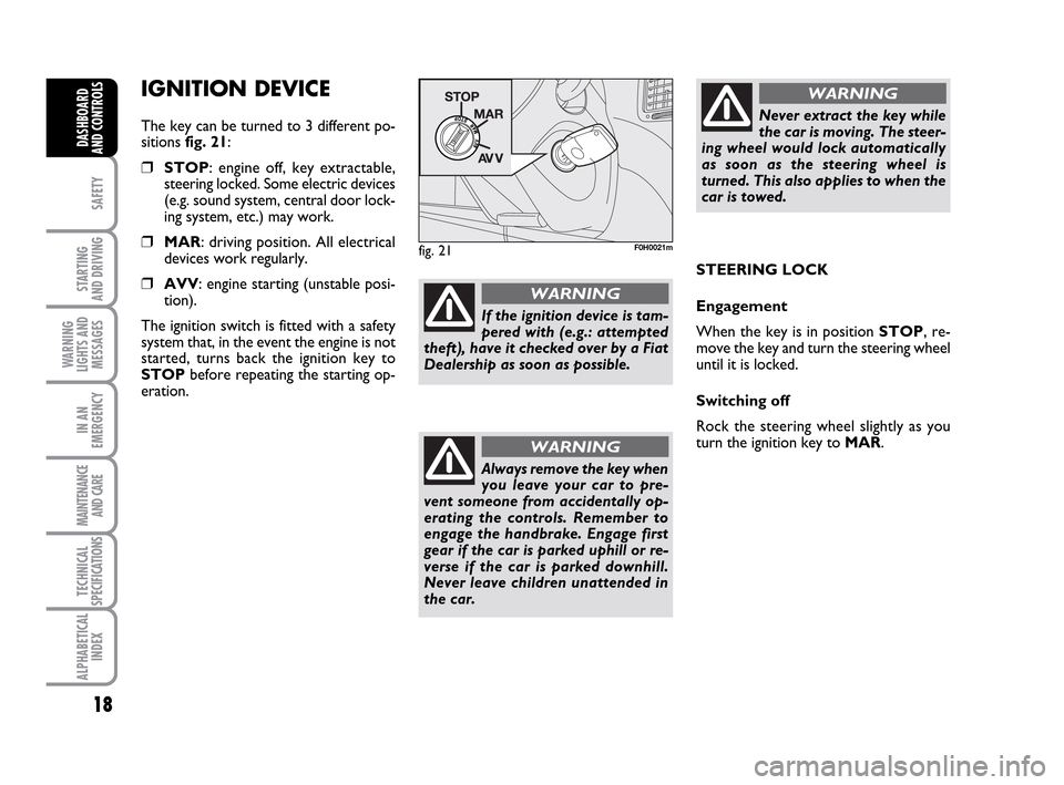
The key can be turned to 3 different po-
sitions fig. 21:
❒STOP: engine off, key extractable,
steering locked. Some electric devices
(e.g. sound system, central door lock-
ing system, etc.) may work.
❒MAR: driving position. All electrical
devices work regularly.
❒AVV: engine starting (unstable posi-
tion).
The ignition switch is fitted with a safety
system that, in the event the engine is not
started, turns back the ignition key to
STOPbefore repeating the starting op-
eration.
fig. 21F0H0021m
STEERING LOCK
Engagement
When the key is in position STOP, re-
move the key and turn the steering wheel
until it is locked.
Switching off
Rock the steering wheel slightly as you
turn the ignition key to MAR.
If the ignition device is tam-
pered with (e.g.: attempted
theft), have it checked over by a Fiat
Dealership as soon as possible.
WARNING
Never extract the key while
the car is moving. The steer-
ing wheel would lock automatically
as soon as the steering wheel is
turned. This also applies to when the
car is towed.
WARNING
Always remove the key when
you leave your car to pre-
vent someone from accidentally op-
erating the controls. Remember to
engage the handbrake. Engage first
gear if the car is parked uphill or re-
verse if the car is parked downhill.
Never leave children unattended in
the car.
WARNING
001-035 LUM IDEA GB 2 ed.qxd 19-01-2010 9:14 Pagina 18
Page 21 of 210
20
SAFETY
STARTING
AND DRIVING
WARNING
LIGHTS AND
MESSAGES
IN AN
EMERGENCY
MAINTENANCE
AND CARE
TECHNICAL
SPECIFICATIONS
ALPHABETICAL
INDEX
DASHBOARD
AND CONTROLS
This shows the temperature of the engine
coolant fluid and starts working when the
fluid temperature exceeds approx. 50°C
circa. In normal conditions, the needle may
point to different positions according to
use and the engine cooling system man-
agement.
IMPORTANT The needle will point to the
lowest value of the scale (low tempera-
ture) and warning light Awill light up to
indicate a fault in the system. Go to a Fi-
at Dealership to have the system checked.
If the needle reaches the red
area, stop the engine imme-
diately and contact a Fiat
Dealership.MULTIFUNCTIONAL
DISPLAY
(on two-line
modal panel)
The car can be equipped with the multi-
function display for showing useful infor-
mation necessary when driving according
to settings.
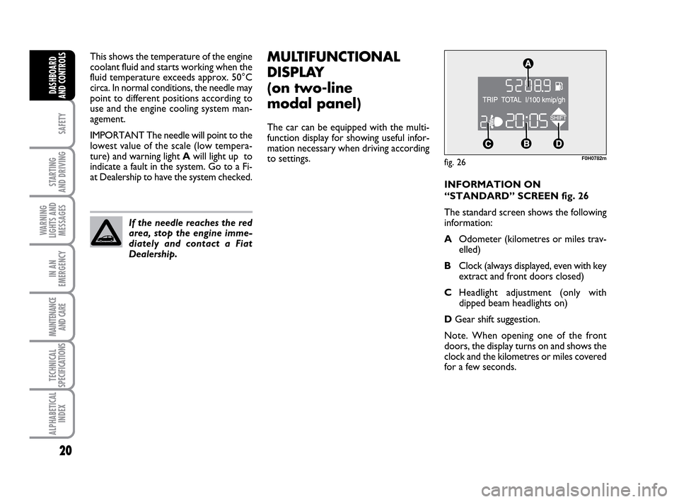
fig. 26F0H0782m
INFORMATION ON
“STANDARD” SCREEN fig. 26
The standard screen shows the following
information:
AOdometer (kilometres or miles trav-
elled)
BClock (always displayed, even with key
extract and front doors closed)
CHeadlight adjustment (only with
dipped beam headlights on)
DGear shift suggestion.
Note. When opening one of the front
doors, the display turns on and shows the
clock and the kilometres or miles covered
for a few seconds.
001-035 LUM IDEA GB 2 ed.qxd 19-01-2010 9:14 Pagina 20
Page 24 of 210
23
SAFETY
STARTING
AND DRIVING
WARNING
LIGHTS AND
MESSAGES
IN AN
EMERGENCY
MAINTENANCE
AND CARE
TECHNICAL
SPECIFICATIONS
ALPHABETICAL
INDEX
DASHBOARD
AND CONTROLS
fig. 28F0H0781m
MULTIFUNCTIONAL
DISPLAY
(on three-line comfort
panel)
The car can be equipped with the multi-
function display for showing useful infor-
mation necessary when driving according
to settings.
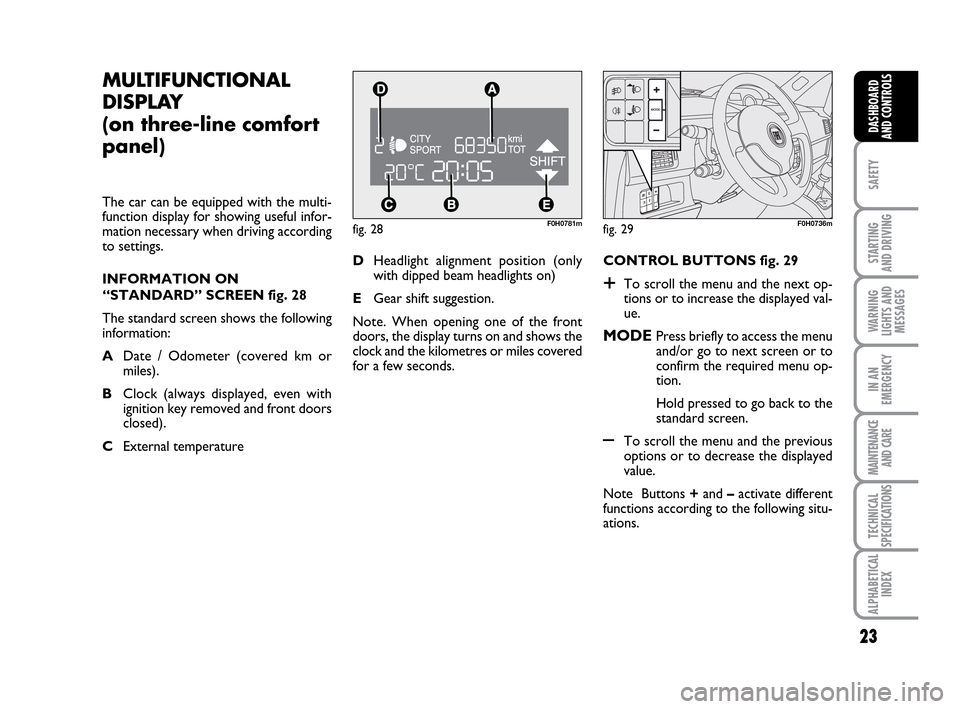
INFORMATION ON
“STANDARD” SCREEN fig. 28
The standard screen shows the following
information:
ADate / Odometer (covered km or
miles).
BClock (always displayed, even with
ignition key removed and front doors
closed).
CExternal temperature CONTROL BUTTONS fig. 29
+To scroll the menu and the next op-
tions or to increase the displayed val-
ue.
MODEPress briefly to access the menu
and/or go to next screen or to
confirm the required menu op-
tion.
Hold pressed to go back to the
standard screen.
–To scroll the menu and the previous
options or to decrease the displayed
value.
Note Buttons +and –activate different
functions according to the following situ-
ations. DHeadlight alignment position (only
with dipped beam headlights on)
EGear shift suggestion.
Note. When opening one of the front
doors, the display turns on and shows the
clock and the kilometres or miles covered
for a few seconds.
fig. 29F0H0736m
001-035 LUM IDEA GB 2 ed.qxd 19-01-2010 9:14 Pagina 23
Page 26 of 210
25
SAFETY
STARTING
AND DRIVING
WARNING
LIGHTS AND
MESSAGES
IN AN
EMERGENCY
MAINTENANCE
AND CARE
TECHNICAL
SPECIFICATIONS
ALPHABETICAL
INDEX
DASHBOARD
AND CONTROLS
Day
YearMonth Example:
CONSUMPTION QUIT MENUSPEED LIMITTRIP B
LIGHT SENS.
CLOCK MODE ECE CLOCK
SET DATE
KEY
UNIT DIST.
BUTTON VOL.
BUZZER VOLUME SERVICE
LANGUAGE TEMP. UNIT
Example:
– +
+– – –
+ +
–
–
+
+++
–––
+ +
–
MODE
button
pressed
briefly
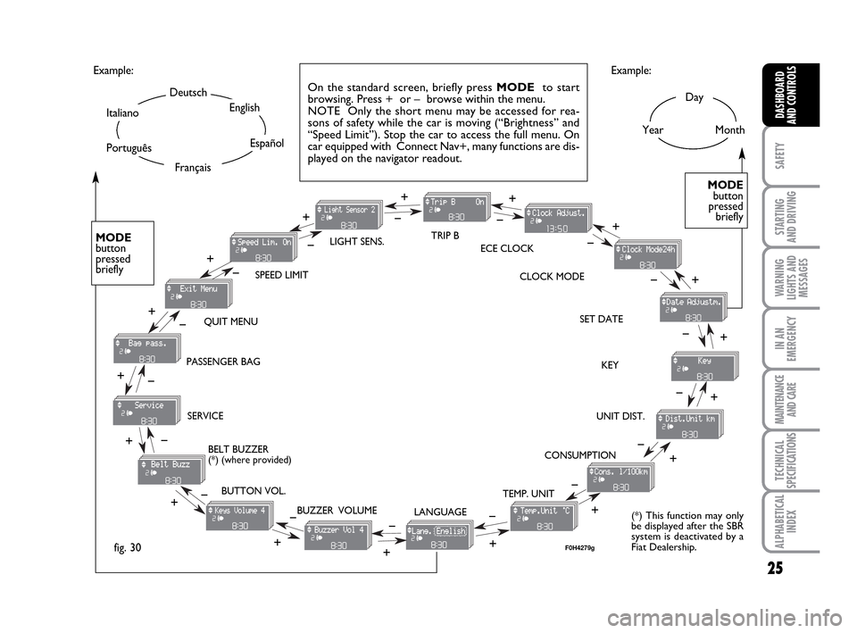
On the standard screen, briefly press MODEto start
browsing. Press + or – browse within the menu.
NOTE Only the short menu may be accessed for rea-
sons of safety while the car is moving (“Brightness” and
“Speed Limit”). Stop the car to access the full menu. On
car equipped with Connect Nav+, many functions are dis-
played on the navigator readout.
–
+ +
–
MODE
button
pressed
briefly
Deutsch
English
Español
Italiano
Português
Français
(*) This function may only
be displayed after the SBR
system is deactivated by a
Fiat Dealership.
fig. 30
+
– +
–+
–
+
–
+ –
BELT BUZZER
(*) (where provided) PASSENGER BAG
F0H4279g
001-035 LUM IDEA GB 2 ed.qxd 19-01-2010 9:14 Pagina 25
Page 29 of 210
28
SAFETY
STARTING
AND DRIVING
WARNING
LIGHTS AND
MESSAGES
IN AN
EMERGENCY
MAINTENANCE
AND CARE
TECHNICAL
SPECIFICATIONS
ALPHABETICAL
INDEX
DASHBOARD
AND CONTROLS
Unlocking the doors and the
tailgate (key)
This function is used to: unlock the front
and rear doors, unlock the driver’s side
door or all the doors including the tailgate.
Proceed as follows to set:
– briefly press button MODE: “Open
doors”, “Open driver”, “Open all”;
– press button +or –to select. The se-
lected item will blink.
– briefly press button MODEto go back
to the menu screen or press the button
for a prolonged time to go back to the
standard screen without storing the set-
tings. – briefly press button MODE: “day” will
start flashing on the display;
– press button +or –to set;
– briefly press button MODE: “day” will
start flashing on the display;
– press button +or –to set.
Note The setting will increase or decrease
by one unit each time +or –is pressed.
Hold the button pressed to in-
crease/decrease the setting rapidly. When
the desired value is reached, end adjust-
ment with a single press.
– briefly press button MODEto go back
to the menu screen or press the button
for a prolonged time to go back to the
standard screen without storing the set-
tings. 12h/24h clock mode
This function is used to select 12h or 24
h display.
To carry out the adjustment, proceed as
follows:
– briefly press MODE: either 12h or 24h
will start flashing on the display (accord-
ing to the previous setting);
– press button +or –for setting;
– briefly press button MODEto go back
to the menu screen or press the button
for a prolonged time to go back to the
standard screen without storing the set-
tings.
Set date
This function is used to set the date (year
– month – day).
Proceed as follows to update:
– briefly press button MODE: “year” will
start flashing on the display;
– press button +or –to set;
001-035 LUM IDEA GB 2 ed.qxd 19-01-2010 9:14 Pagina 28
Page 32 of 210
31
SAFETY
STARTING
AND DRIVING
WARNING
LIGHTS AND
MESSAGES
IN AN
EMERGENCY
MAINTENANCE
AND CARE
TECHNICAL
SPECIFICATIONS
ALPHABETICAL
INDEX
DASHBOARD
AND CONTROLS
Adjust the button volume
(Button Vol.)
This function is used to set the volume of
the roger-beep accompanying the activa-
tion of buttons MODE, +e –through 8
levels.
To set the desired volume, proceed as fol-
lows:
– briefly press button MODE: the previ-
ously set volume “level” starts flashing on
the display;
– press button +or –to set;
– briefly press button MODEto go back
to the menu screen or press the button
for a prolonged time to go back to the
standard screen without storing the set-
tings.
S.B.R. buzzer reactivation (Belt
Buzzer) (where provided)
This function can be only displayed after a
Fiat Dealership has deactivated the S.B.R.
system (see paragraph “S.B.R. system” in
section “Safety devices”).The indications will appear more fre-
quently where there are 200 km left. For
1.3 Multijet versions, refer to the “Service
Schedule” in the “Maintenance and care”
chapter for replacing the air cleaner, the
engine oil and the engine oil filter. The in-
dication will appear in kilometres or miles
according to the settings. When the next
scheduled service operation is approach-
ing, the message “Service” will appear on
the display followed by the number of kilo-
metres or miles left when the key is
turned to MAR. The “Service Schedule”
information is provided with kilometres
(km)/miles (mi) or days (dd), according to
the deadline which appears first. Go to a
Fiat Dealership where the “Scheduled Ser-
vice” operations will be performed and the
message will be reset. Scheduled Servicing (Service)
This function may be used to display in-
formation connected to proper car ser-
vicing in terms of kilometres or days.
This information can be consulted as fol-
lows:
–briefly press button MODE: service in
km or mi, according to previous setting,
will be displayed (see paragraph “Units”);
– press button +or –to set deadline in
days;
– briefly press button MODEto go back
to the menu screen or hold the button
pressed to go back to the standard screen.
Note The “Service Schedule” requires the
car to be services every 20,000 km (or
equivalent distance in miles) or once a
year. This message will appear automati-
cally with key at MARafter 2,000 km (or
equivalent distance in miles) or 30 before
the deadline and will appear every 200 km
(or equivalent distance in miles) or 3 days.
001-035 LUM IDEA GB 2 ed.qxd 19-01-2010 9:14 Pagina 31
Page 34 of 210
33
SAFETY
STARTING
AND DRIVING
WARNING
LIGHTS AND
MESSAGES
IN AN
EMERGENCY
MAINTENANCE
AND CARE
TECHNICAL
SPECIFICATIONS
ALPHABETICAL
INDEX
DASHBOARD
AND CONTROLS
Quit menu
This function closes the cycle of settings
listed in the menu screen.
Briefly press button MODEto go back to
the standard screen without storing the
settings.
Press button +to return to the first menu
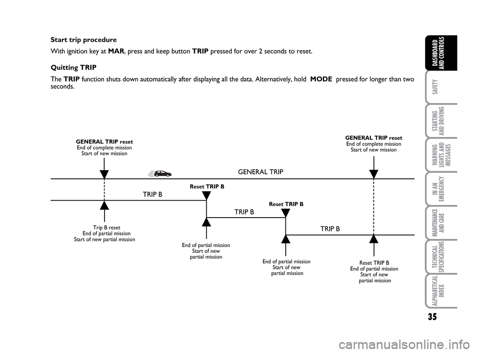
option (Speed Limit).Both functions can be reset (to start a new
trip). The following data can be displayed
for “General Trip”:
– Range
– Distance travelled
– Average consumption
– Instant consumption
– Average speed
– Travel time (driving time).
“Trip B” may be used to display the figures
relating to:
– Distance travelled B
– Average consumption B
– Average speed B
– Travel time (driving time).
Note “Trip B” functions may be exclud-
ed (see “Trip B on”). “Range” and “In-
stantaneous consumption” cannot be re-
set. TRIP COMPUTER (where
provided)
General information
The “Trip computer” is used to display in-
formation on car operation when the key
is turned to MAR. This function consists
of “General trip” for displaying the com-
plete mission of the car and by “Trip B”,
for trips; this function is included in the
general trip information (as shown in fig.
32).
001-035 LUM IDEA GB 2 ed.qxd 19-01-2010 9:14 Pagina 33
Page 35 of 210
34
SAFETY
STARTING
AND DRIVING
WARNING
LIGHTS AND
MESSAGES
IN AN
EMERGENCY
MAINTENANCE
AND CARE
TECHNICAL
SPECIFICATIONS
ALPHABETICAL
INDEX
DASHBOARD
AND CONTROLS
New mission
The new mission begins after:– “manu-
al” resetting by the user, by pressing the
relevant button;
– “automatic” resetting, when the “Trip
distance” reaches 3999.9 km or 9999.9 km
(according to the type of display) or when
the “Travel time” reaches 99.59 (99 hours
and 59 minutes);
– after disconnecting/reconnecting the
battery.
IMPORTANT “General Trip” resets will
reset “Trip B” at the same time, while re-
setting “Trip B” will only reset the val-
ues of the trip B function. Average speed
This shows the car average speed as a
function of the overall time elapsed since
the start of the new mission.Journey time
This value shows the time elapsed since
the start of the new mission.
IMPORTANT If information is not avail-
able, the message “----” will appear instead
of the Trip Computer values. Displaying
of the values will be resumed when nor-
mal operation is restored without reset-
ting the values displayed before the prob-
lem nor starting a new mission.
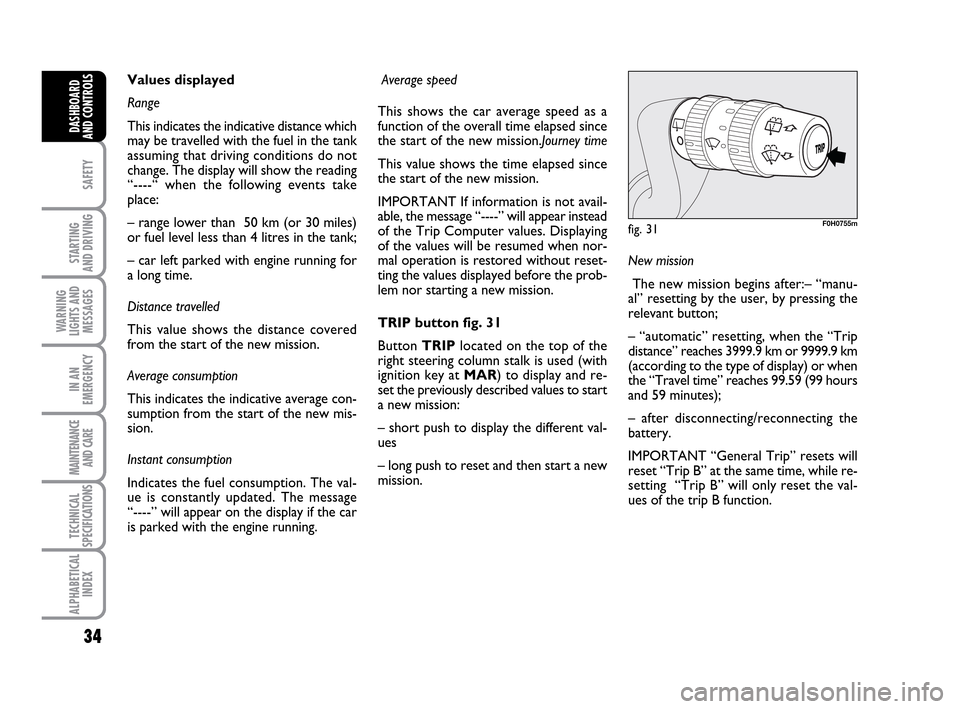
TRIP button fig. 31
Button TRIPlocated on the top of the
right steering column stalk is used (with
ignition key at MAR) to display and re-
set the previously described values to start
a new mission:
– short push to display the different val-
ues
– long push to reset and then start a new
mission. Values displayed
Range
This indicates the indicative distance which
may be travelled with the fuel in the tank
assuming that driving conditions do not
change. The display will show the reading
“----“ when the following events take
place:
– range lower than 50 km (or 30 miles)
or fuel level less than 4 litres in the tank;
– car left parked with engine running for
a long time.
Distance travelled
This value shows the distance covered
from the start of the new mission.
Average consumption
This indicates the indicative average con-
sumption from the start of the new mis-
sion.
Instant consumption
Indicates the fuel consumption. The val-
ue is constantly updated. The message
“----” will appear on the display if the car
is parked with the engine running.
fig. 31F0H0755m
001-035 LUM IDEA GB 2 ed.qxd 19-01-2010 9:14 Pagina 34
Page 36 of 210
35
SAFETY
STARTING
AND DRIVING
WARNING
LIGHTS AND
MESSAGES
IN AN
EMERGENCY
MAINTENANCE
AND CARE
TECHNICAL
SPECIFICATIONS
ALPHABETICAL
INDEX
DASHBOARD
AND CONTROLS
Start trip procedure
With ignition key at MAR, press and keep button TRIPpressed for over 2 seconds to reset.
Quitting TRIP
The TRIP function shuts down automatically after displaying all the data. Alternatively, hold MODE pressed for longer than two
seconds.
Trip B reset
End of partial mission
Start of new partial mission
End of partial mission
Start of new
partial mission
Reset TRIP B
End of partial mission
Start of new
partial mission GENERAL TRIP reset
End of complete mission
Start of new missionGENERAL TRIP reset
End of complete mission
Start of new mission
End of partial mission
Start of new
partial mission Reset TRIP B
Reset TRIP B
TRIP B
TRIP B
TRIP B GENERAL TRIP
˙
˙
˙
˙
˙
˙˙
˙
001-035 LUM IDEA GB 2 ed.qxd 19-01-2010 9:14 Pagina 35
Page 44 of 210
43
SAFETY
STARTING
AND DRIVING
WARNING
LIGHTS AND
MESSAGES
IN AN
EMERGENCY
MAINTENANCE
AND CARE
TECHNICAL
SPECIFICATIONS
ALPHABETICAL
INDEX
DASHBOARD
AND CONTROLS
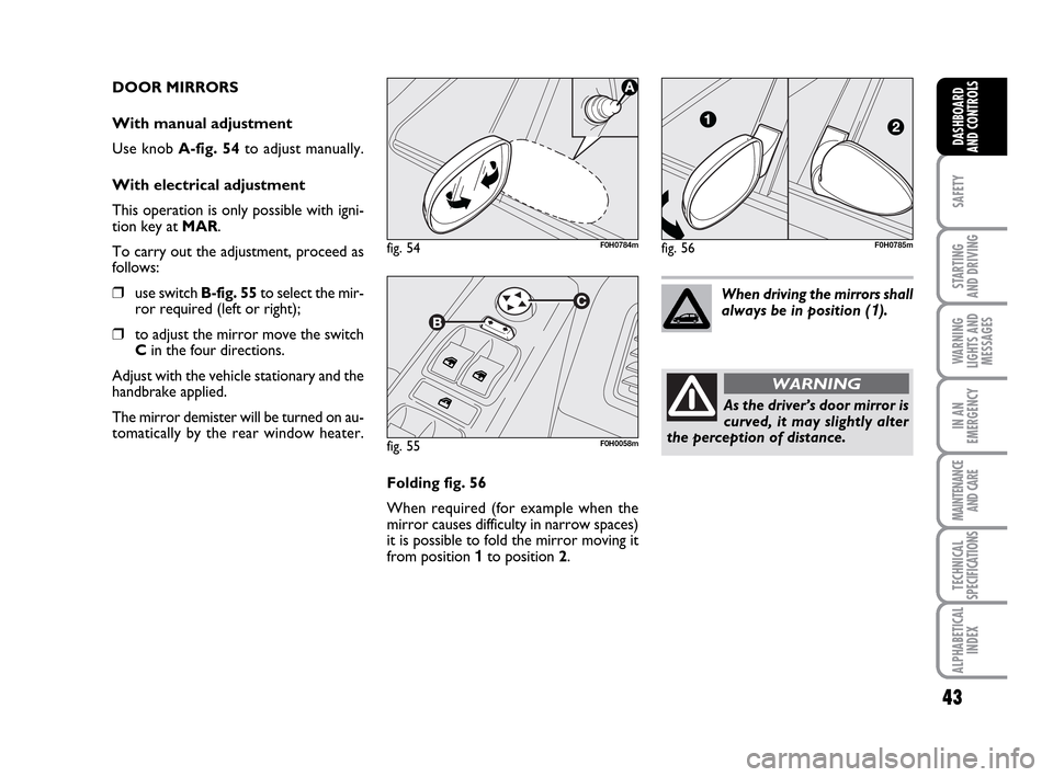
DOOR MIRRORS
With manual adjustment
Use knob A-fig. 54to adjust manually.
With electrical adjustment
This operation is only possible with igni-
tion key at MAR.
To carry out the adjustment, proceed as
follows:
❒use switch B-fig. 55to select the mir-
ror required (left or right);
❒to adjust the mirror move the switch
Cin the four directions.
Adjust with the vehicle stationary and the
handbrake applied.
The mirror demister will be turned on au-
tomatically by the rear window heater.
fig. 55F0H0058m
Folding fig. 56
When required (for example when the
mirror causes difficulty in narrow spaces)
it is possible to fold the mirror moving it
from position 1 to position 2.When driving the mirrors shall
always be in position (
1).
As the driver’s door mirror is
curved, it may slightly alter
the perception of distance.
WARNING
fig. 54F0H0784mfig. 56F0H0785m
036-092 LUM IDEA GB 2 ed.qxd 14-01-2010 12:14 Pagina 43