display FIAT IDEA 2010 1.G Owner's Manual
[x] Cancel search | Manufacturer: FIAT, Model Year: 2010, Model line: IDEA, Model: FIAT IDEA 2010 1.GPages: 210, PDF Size: 4.4 MB
Page 52 of 210
51
SAFETY
STARTING
AND DRIVING
WARNING
LIGHTS AND
MESSAGES
IN AN
EMERGENCY
MAINTENANCE
AND CARE
TECHNICAL
SPECIFICATIONS
ALPHABETICAL
INDEX
DASHBOARD
AND CONTROLS
AUTOMATIC TWO-
ZONE CLIMATE
CONTROL SYSTEM
(where provided)
GENERAL INFORMATION
The two-zone automatic climate control
system distributes air in the passenger
compartment in two zones: driver’s and
passenger’s side. Temperature is con-
trolled on the basis of an “equivalent tem-
perature” principle; in other words, the
system continuously works to keep the
comfort level inside the car constant and
to compensate for possible variations of
external conditions, including sun radia-
tion detected by a specific sensor.
The automatically controlled parameters
and functions are:
❒air temperature at the vents on dri-
ver/front passenger side;
❒air at vents on driver/front passenger
side;
❒fan speed (continuous air flow varia-
tion);
❒compressor activation (to cool/dehu-
midify air);
❒air recirculation.All functions may be manually changed. In
order words, you may select one or more
functions and change the parameters as
required. Automatic control of the man-
ually changed functions will be suspended:
the system will change override your set-
tings only for safety-related reasons (e.g.
risk of misting up).
Manual selections will always have higher
priority over automatic settings and will
be stored until the user switches the sys-
tem back to automatic mode, except for
the cases in which the system will inter-
vene for particular, safety-related reasons.
You can adjust one function automatical-
ly and have the automatic system control
all the others.
The amount of air introduced into the pas-
senger compartment is independent from
speed of the car because the fan is con-
trolled by the electronic system.
The temperature of the air taken in is al-
ways controlled automatically depending
on the temperature set on the display (ex-
cept when the system is turned off or un-
der certain conditions when the com-
pressor is off. The following parameters and functions
can be manually set:
❒air temperature on driver/front pas-
senger side;
❒fan speed (continuous variation);
❒air distribution to five positions (dri-
ver/front passenger side);
❒compressor enablement;
❒one-zone/two-zone distribution pri-
ority;
❒fast demist/defrost function;
❒air recirculation;
❒heated rear window;
❒system off.
036-092 LUM IDEA GB 2 ed.qxd 14-01-2010 12:14 Pagina 51
Page 53 of 210
52
SAFETY
STARTING
AND DRIVING
WARNING
LIGHTS AND
MESSAGES
IN AN
EMERGENCY
MAINTENANCE
AND CARE
TECHNICAL
SPECIFICATIONS
ALPHABETICAL
INDEX
DASHBOARD
AND CONTROLS
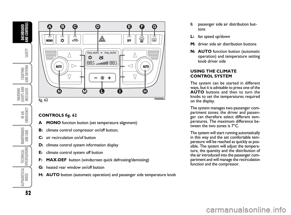
CONTROLS fig. 62
A MONOfunction button (set temperature alignment)
B:climate control compressor on/off button;
C: air recirculation on/of button
D:climate control system information display
E:climate control system off button
F: MAX-DEFbutton (windscreen quick defrosting/demisting)
G:heated rear window on/off button
H: AUTObutton (automatic operation) and passenger side temperature knob
F0H0065m
I:passenger side air distribution but-
tons
L:fan speed up/down
M:driver side air distribution buttons
N: AUTOfunction button (automatic
operation) and temperature setting
knob driver side
USING THE CLIMATE
CONTROL SYSTEM
The system can be started in different
ways, but it is advisable to press one of the
AUTObuttons and then to turn the
knobs to set the temperatures required
on the display.
The system manages two passenger com-
partment zones: the driver and passen-
ger can therefore select different tem-
peratures. The maximum difference be-
tween the two zones is 7°C.
The system will start running automatically
in this way and the set comfortable tem-
perature will be reached as quickly as pos-
sible. The system will adjust the tempera-
ture, the quantity and the distribution of
the air introduced into the passenger com-
partment and will manage the recirculation
function and the compressor.
fig. 62
036-092 LUM IDEA GB 2 ed.qxd 14-01-2010 12:14 Pagina 52
Page 56 of 210
55
SAFETY
STARTING
AND DRIVING
WARNING
LIGHTS AND
MESSAGES
IN AN
EMERGENCY
MAINTENANCE
AND CARE
TECHNICAL
SPECIFICATIONS
ALPHABETICAL
INDEX
DASHBOARD
AND CONTROLS
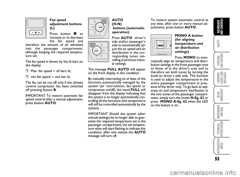
Fan speed
adjustment buttons
(L)
Press button pto
increase or to decrease
the fan speed and
therefore the amount of air admitted
into the passenger compartment,
although keeping the required tempera-
ture set.
The fan speed is shown by the lit bars on
the display:
❒Max. fan speed = all bars lit;
❒min fan speed = one bar lit.
The fan can be cut off only if the climate
control compressor has been switched
off pressing button B.
IMPORTANT To restore automatic fan
speed control after a manual adjustment,
press button AUTO.AUTO
(H-N)
buttons (automatic
operation)
Press AUTOdriver’s
side and/or passenger’s
side to automatically ad-
just the air speed and air
distribution in the cor-
responding zones can-
celling al previous manu-
al settings.
The message FULL AUTOwill appear
on the front display in this condition.
By manually intervening on at least of the
functions automatically managed by the
system (air recirculation, fan speed or
compressor on/off), the word FULL will
disappear from the display indicating that
the system is no longer automatically con-
trolling all the functions (the temperature
will still be controlled automatically by the
system).
IMPORTANT Should the system (after
manual settings) be no longer able to guar-
antee the required temperature set in the
passenger compartment, the set tempera-
ture value will start flashing to indicate this
condition, after one minute the AUTO
message will turn off.To restore system automatic control at
any time, after one or more manual ad-
justments, press button AUTO.
MONO A button
(for aligning
temperature and
air distribution
settings)
Press MONOto auto-
matically align air temperature and distri-
bution settings in the front passenger area
to those of in the driver’s area and to
therefore set both zones by turning the
knob on driver’s side only. This function
is used to adjust the temperature in the
entire passenger compartment in pres-
ence of the driver only. To go back to sep-
arate air and temperature distribution in
the two zones of the passenger compart-
ment, simply turn the knobs H-fig. 62or
press MONO A-fig. 62when the LED
on the button is on.
036-092 LUM IDEA GB 2 ed.qxd 14-01-2010 12:14 Pagina 55
Page 57 of 210
56
SAFETY
STARTING
AND DRIVING
WARNING
LIGHTS AND
MESSAGES
IN AN
EMERGENCY
MAINTENANCE
AND CARE
TECHNICAL
SPECIFICATIONS
ALPHABETICAL
INDEX
DASHBOARD
AND CONTROLS
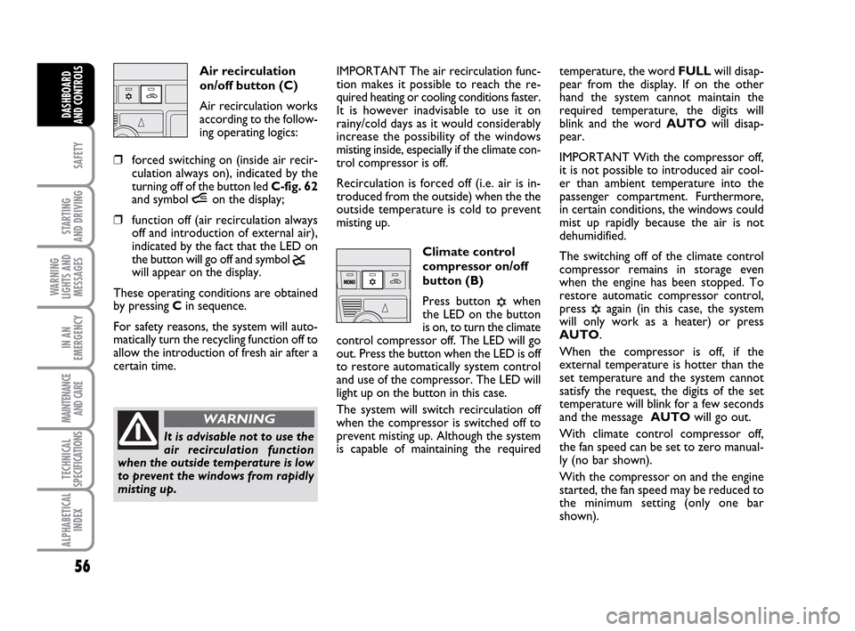
Air recirculation
on/off button (C)
Air recirculation works
according to the follow-
ing operating logics:
❒forced switching on (inside air recir-
culation always on), indicated by the
turning off of the button led C-fig. 62
and symbol íon the display;
❒function off (air recirculation always
off and introduction of external air),
indicated by the fact that the LED on
the button will go off and symbol
ê
will appear on the display.
These operating conditions are obtained
by pressing Cin sequence.
For safety reasons, the system will auto-
matically turn the recycling function off to
allow the introduction of fresh air after a
certain time.IMPORTANT The air recirculation func-
tion makes it possible to reach the re-
quired heating or cooling conditions faster.
It is however inadvisable to use it on
rainy/cold days as it would considerably
increase the possibility of the windows
misting inside, especially if the climate con-
trol compressor is off.
Recirculation is forced off (i.e. air is in-
troduced from the outside) when the the
outside temperature is cold to prevent
misting up.
Climate control
compressor on/off
button (B)
Press button
√when
the LED on the button
is on, to turn the climate
control compressor off. The LED will go
out. Press the button when the LED is off
to restore automatically system control
and use of the compressor. The LED will
light up on the button in this case.
The system will switch recirculation off
when the compressor is switched off to
prevent misting up. Although the system
is capable of maintaining the requiredtemperature, the word FULLwill disap-
pear from the display. If on the other
hand the system cannot maintain the
required temperature, the digits will
blink and the word AUTOwill disap-
pear.
IMPORTANT With the compressor off,
it is not possible to introduced air cool-
er than ambient temperature into the
passenger compartment. Furthermore,
in certain conditions, the windows could
mist up rapidly because the air is not
dehumidified.
The switching off of the climate control
compressor remains in storage even
when the engine has been stopped. To
restore automatic compressor control,
press √again (in this case, the system
will only work as a heater) or press
AUTO.
When the compressor is off, if the
external temperature is hotter than the
set temperature and the system cannot
satisfy the request, the digits of the set
temperature will blink for a few seconds
and the message AUTOwill go out.
With climate control compressor off,
the fan speed can be set to zero manual-
ly (no bar shown).
With the compressor on and the engine
started, the fan speed may be reduced to
the minimum setting (only one bar
shown).
It is advisable not to use the
air recirculation function
when the outside temperature is low
to prevent the windows from rapidly
misting up.
WARNING
036-092 LUM IDEA GB 2 ed.qxd 14-01-2010 12:14 Pagina 56
Page 58 of 210
57
SAFETY
STARTING
AND DRIVING
WARNING
LIGHTS AND
MESSAGES
IN AN
EMERGENCY
MAINTENANCE
AND CARE
TECHNICAL
SPECIFICATIONS
ALPHABETICAL
INDEX
DASHBOARD
AND CONTROLS
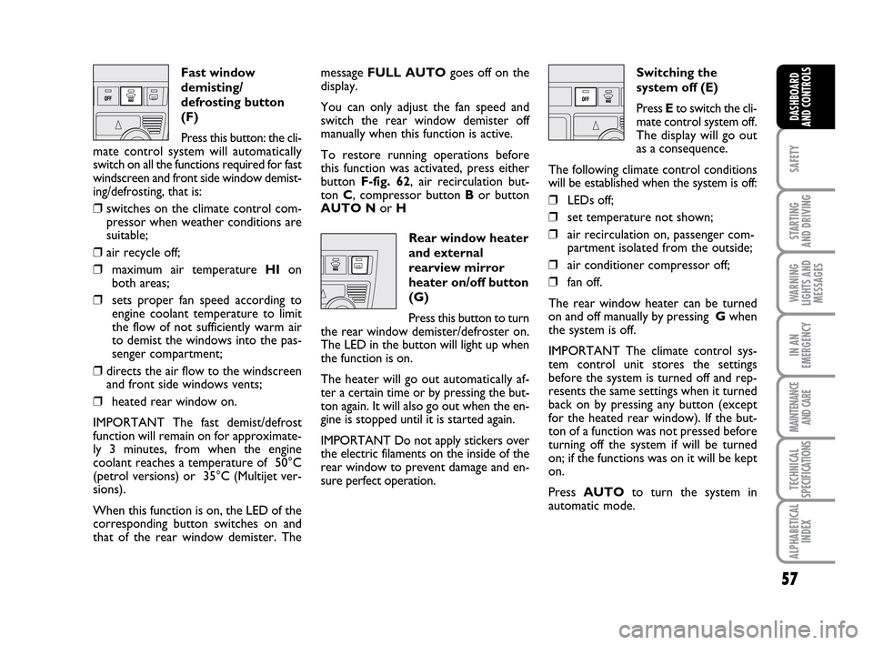
Fast window
demisting/
defrosting button
(F)
Press this button: the cli-
mate control system will automatically
switch on all the functions required for fast
windscreen and front side window demist-
ing/defrosting, that is:
❒switches on the climate control com-
pressor when weather conditions are
suitable;
❒air recycle off;
❒maximum air temperature HIon
both areas;
❒sets proper fan speed according to
engine coolant temperature to limit
the flow of not sufficiently warm air
to demist the windows into the pas-
senger compartment;
❒directs the air flow to the windscreen
and front side windows vents;
❒heated rear window on.
IMPORTANT The fast demist/defrost
function will remain on for approximate-
ly 3 minutes, from when the engine
coolant reaches a temperature of 50°C
(petrol versions) or 35°C (Multijet ver-
sions).
When this function is on, the LED of the
corresponding button switches on and
that of the rear window demister. Themessage FULL AUTOgoes off on the
display.
You can only adjust the fan speed and
switch the rear window demister off
manually when this function is active.
To restore running operations before
this function was activated, press either
button F-fig. 62, air recirculation but-
ton C, compressor button Bor button
AUTO Nor H
Rear window heater
and external
rearview mirror
heater on/off button
(G)
Press this button to turn
the rear window demister/defroster on.
The LED in the button will light up when
the function is on.
The heater will go out automatically af-
ter a certain time or by pressing the but-
ton again. It will also go out when the en-
gine is stopped until it is started again.
IMPORTANT Do not apply stickers over
the electric filaments on the inside of the
rear window to prevent damage and en-
sure perfect operation.Switching the
system off (E)
Press Eto switch the cli-
mate control system off.
The display will go out
as a consequence.
The following climate control conditions
will be established when the system is off:
❒LEDs off;
❒set temperature not shown;
❒air recirculation on, passenger com-
partment isolated from the outside;
❒air conditioner compressor off;
❒fan off.
The rear window heater can be turned
on and off manually by pressing Gwhen
the system is off.
IMPORTANT The climate control sys-
tem control unit stores the settings
before the system is turned off and rep-
resents the same settings when it turned
back on by pressing any button (except
for the heated rear window). If the but-
ton of a function was not pressed before
turning off the system if will be turned
on; if the functions was on it will be kept
on.
Press AUTOto turn the system in
automatic mode.
036-092 LUM IDEA GB 2 ed.qxd 14-01-2010 12:14 Pagina 57
Page 61 of 210
60
SAFETY
STARTING
AND DRIVING
WARNING
LIGHTS AND
MESSAGES
IN AN
EMERGENCY
MAINTENANCE
AND CARE
TECHNICAL
SPECIFICATIONS
ALPHABETICAL
INDEX
DASHBOARD
AND CONTROLS
WINDOW CLEANING
WINDSCREEN WASHER/
WIPER
The device can only work when the igni-
tion key is at MAR.
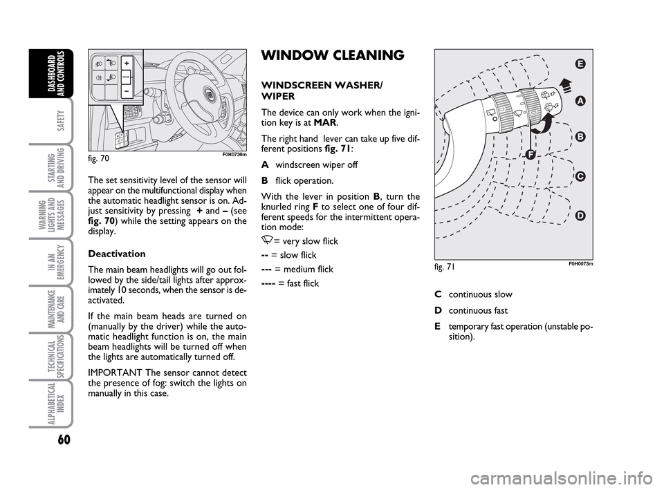
The right hand lever can take up five dif-
ferent positions fig. 71:
Awindscreen wiper off
Bflick operation.
With the lever in position B, turn the
knurled ring Fto select one of four dif-
ferent speeds for the intermittent opera-
tion mode:
,= very slow flick
--= slow flick
---= medium flick
----= fast flick The set sensitivity level of the sensor will
appear on the multifunctional display when
the automatic headlight sensor is on. Ad-
just sensitivity by pressing +and –(see
fig. 70) while the setting appears on the
display.
Deactivation
The main beam headlights will go out fol-
lowed by the side/tail lights after approx-
imately 10 seconds, when the sensor is de-
activated.
If the main beam heads are turned on
(manually by the driver) while the auto-
matic headlight function is on, the main
beam headlights will be turned off when
the lights are automatically turned off.
IMPORTANT The sensor cannot detect
the presence of fog: switch the lights on
manually in this case.
fig. 70F0H0736m
fig. 71F0H0073m
Ccontinuous slow
Dcontinuous fast
Etemporary fast operation (unstable po-
sition).
036-092 LUM IDEA GB 2 ed.qxd 14-01-2010 12:15 Pagina 60
Page 68 of 210
67
SAFETY
STARTING
AND DRIVING
WARNING
LIGHTS AND
MESSAGES
IN AN
EMERGENCY
MAINTENANCE
AND CARE
TECHNICAL
SPECIFICATIONS
ALPHABETICAL
INDEX
DASHBOARD
AND CONTROLS
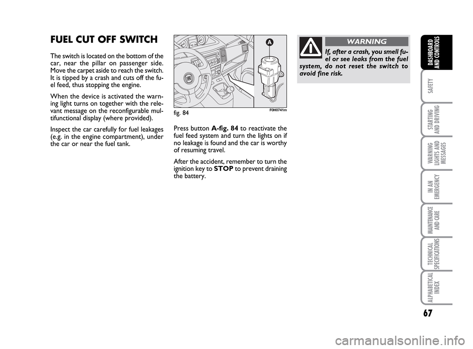
FUEL CUT OFF SWITCH
The switch is located on the bottom of the
car, near the pillar on passenger side.
Move the carpet aside to reach the switch.
It is tipped by a crash and cuts off the fu-
el feed, thus stopping the engine.
When the device is activated the warn-
ing light turns on together with the rele-
vant message on the reconfigurable mul-
tifunctional display (where provided).
Inspect the car carefully for fuel leakages
(e.g. in the engine compartment), under
the car or near the fuel tank. Press button A-fig. 84to reactivate the
fuel feed system and turn the lights on if
no leakage is found and the car is worthy
of resuming travel.
After the accident, remember to turn the
ignition key to STOPto prevent draining
the battery.
fig. 84F0H0741m
If, after a crash, you smell fu-
el or see leaks from the fuel
system, do not reset the switch to
avoid fine risk.
WARNING
036-092 LUM IDEA GB 2 ed.qxd 14-01-2010 12:15 Pagina 67
Page 77 of 210
76
SAFETY
STARTING
AND DRIVING
WARNING
LIGHTS AND
MESSAGES
IN AN
EMERGENCY
MAINTENANCE
AND CARE
TECHNICAL
SPECIFICATIONS
ALPHABETICAL
INDEX
DASHBOARD
AND CONTROLS
BOOT
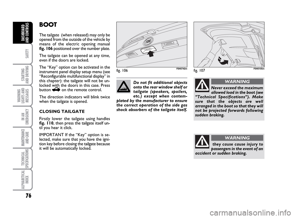
The tailgate (when released) may only be
opened from the outside of the vehicle by
means of the electric opening manual
fig. 106 positioned over the number plate.
The tailgate can be opened at any time,
even if the doors are locked.
The “Key” option can be activated in the
instrument panel display setup menu (see
“Reconfigurable multifunctional display” in
this chapter): the tailgate will not be un-
locked with the doors in this case. Press
button
Ron the remote control.
The direction indicators will blink twice
when the tailgate is opened.
CLOSING TAILGATE
Firstly lower the tailgate using handles
fig. 110, then press the tailgate itself un-
til you hear it click.
IMPORTANT If the “Key” option is se-
lected, make sure that you have the igni-
tion key before closing the tailgate because
it will be automatically locked.
fig. 106F0H0742m
Do not fit additional objects
onto the rear window shelf or
tailgate (speakers, spoilers,
etc.) except when contem-
plated by the manufacturer to ensure
the correct operation of the side gas
shock absorbers of the tailgate itself.
Never exceed the maximum
allowed load in the boot (see
“Technical Specifications”). Make
sure that the objects are well
arranged in the boot so that they will
not be projected forwards following
sudden braking.
WARNING
they cause cause injury to
passengers in the event of an
accident or sudden braking.
WARNING
fig. 107F0H0105m
036-092 LUM IDEA GB 2 ed.qxd 14-01-2010 12:15 Pagina 76
Page 83 of 210
82
SAFETY
STARTING
AND DRIVING
WARNING
LIGHTS AND
MESSAGES
IN AN
EMERGENCY
MAINTENANCE
AND CARE
TECHNICAL
SPECIFICATIONS
ALPHABETICAL
INDEX
DASHBOARD
AND CONTROLS
HEADLIGHTS
BEAM DIRECTION
Correct direction of the headlights is es-
sential for the comfort and safety of the
driver and the other road users. The head-
lights must be correctly directed to ensure
the best visibility conditions when the
headlights are on. Contact a Fiat Dealer-
ship to have the headlights properly ad-
justed.
HEADLIGHT CORRECTOR
This device works with the key at MAR
and the dipped beam headlights on. The
car will slant backwards when it is loaded,
raising the light beam. The beams must
therefore be directed again in this case.
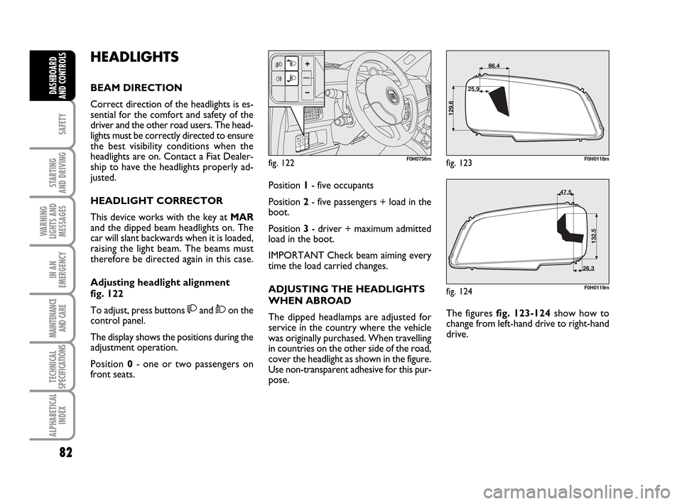
Adjusting headlight alignment
fig. 122
To adjust, press buttons
and Òon the
control panel.
The display shows the positions during the
adjustment operation.
Position 0- one or two passengers on
front seats.
fig. 122F0H0756m
Position 1- five occupants
Position 2- five passengers + load in the
boot.
Position 3- driver + maximum admitted
load in the boot.
IMPORTANT Check beam aiming every
time the load carried changes.
ADJUSTING THE HEADLIGHTS
WHEN ABROAD
The dipped headlamps are adjusted for
service in the country where the vehicle
was originally purchased. When travelling
in countries on the other side of the road,
cover the headlight as shown in the figure.
Use non-transparent adhesive for this pur-
pose.The figures fig. 123-124 show how to
change from left-hand drive to right-hand
drive.
fig. 123F0H0118m
fig. 124F0H0119m
036-092 LUM IDEA GB 2 ed.qxd 14-01-2010 12:15 Pagina 82
Page 84 of 210
83
SAFETY
STARTING
AND DRIVING
WARNING
LIGHTS AND
MESSAGES
IN AN
EMERGENCY
MAINTENANCE
AND CARE
TECHNICAL
SPECIFICATIONS
ALPHABETICAL
INDEX
DASHBOARD
AND CONTROLS
ABS SYSTEM
If you have never driven a vehicle with
ABS before, it is advisable to perform a
few tests on slippery ground, naturally in
conditions of safety and respecting the
Highway Code of the country where you
are driving. Read the following informa-
tion carefully.
The car is fitted with an ABS braking sys-
tem, which prevents the wheels from lock-
ing when braking, makes the most of road
grip and gives the best control when
emergency braking under difficulty road
conditions.
System is completed by EBD (Electronic
Braking force Distribution), which dis-
tributes the braking action between front
and rear wheels.
IMPORTANT The braking system needs
to settle for approximately 500 km: dur-
ing this time, avoid sudden, repeated and
prolonged braking.ABS SYSTEM INTERVENTION
Intervention of the ABS is detected by a
slight pulsing of the brake pedal accom-
panied by noise: such an event indicates
that you need to adjust your speed to the
type of road on which you are travelling.
When the ABS intervenes it means that
you are approaching the grip limit be-
tween tyres and road: slow down to ex-
ploit all the available grip.
FAILURE INDICATIONS
ABS failure
ABS failure is indicated by the turning on
of warning light
>on the instrument pan-
el together with the dedicated message on
the multifunctional display (where pro-
vided), (see section “Warning lights and
messages”). In the case, the braking sys-
tem will work as normal without the ex-
tra potentials offered by the ABS system.
Drive carefully to the nearest Fiat Deal-
ership to have the system checked.EBD failure
ABS failure is indicated by the turning on
of warning light >and xon the instru-
ment panel together with the dedicated
message on the multifunctional display
(where provided), (see section “Warning
lights and messages”). In this case, the rear
wheels may suddenly lock and the vehi-
cle may swerve when braking sharply. Dri-
ve carefully to the nearest Fiat Dealership
to have the system checked.
When the ABS intervenes it
means that you are ap-
proaching the grip limit between tyres
and road: slow down to exploit all the
available grip.
WARNING
The ABS exploits the tyre-
road grip at the best, but it
cannot improve it; you should there-
fore take every care when driving on
slippery surfaces without taking un-
necessary risks.
WARNING
When the ABS cuts in, and
you feel the brake pedal pul-
sating, do not remove your foot, but
keep it pressed; in doing so you will
stop in the shortest amount of space
possible under the current road con-
ditions.
WARNING
036-092 LUM IDEA GB 2 ed.qxd 14-01-2010 12:15 Pagina 83