tailgate FIAT IDEA 2012 1.G Owners Manual
[x] Cancel search | Manufacturer: FIAT, Model Year: 2012, Model line: IDEA, Model: FIAT IDEA 2012 1.GPages: 210, PDF Size: 3.65 MB
Page 12 of 210
11
SAFETY
DEVICES
CORRECT USE
OF THE CAR
WARNING
LIGHTS AND
MESSAGES
IN AN
EMERGENCY
CAR
MAINTENANCE
TECHNICAL
SPECIFICATIONS
INDEX
DASHBOARD
AND CONTROLS
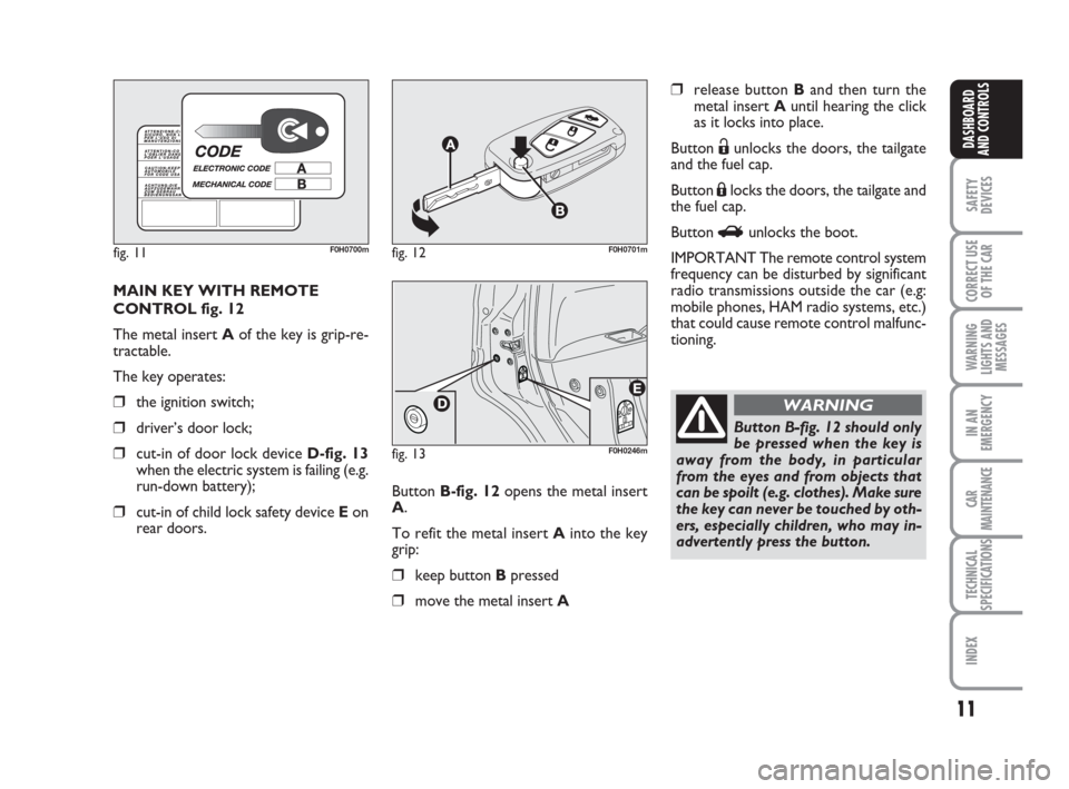
MAIN KEY WITH REMOTE
CONTROL fig. 12
The metal insert Aof the key is grip-re-
tractable.
The key operates:
❒the ignition switch;
❒driver’s door lock;
❒cut-in of door lock device D-fig. 13
when the electric system is failing (e.g.
run-down battery);
❒cut-in of child lock safety device Eon
rear doors.
fig. 11F0H0700mfig. 12F0H0701m
fig. 13F0H0246m
Button B-fig. 12opens the metal insert
A.
To refit the metal insert Ainto the key
grip:
❒keep button Bpressed
❒move the metal insert A
❒release button Band then turn the
metal insert Auntil hearing the click
as it locks into place.
Button
Ëunlocks the doors, the tailgate
and the fuel cap.
Button Álocks the doors, the tailgate and
the fuel cap.
Button
Runlocks the boot.
IMPORTANT The remote control system
frequency can be disturbed by significant
radio transmissions outside the car (e.g:
mobile phones, HAM radio systems, etc.)
that could cause remote control malfunc-
tioning.
Button B-fig. 12 should only
be pressed when the key is
away from the body, in particular
from the eyes and from objects that
can be spoilt (e.g. clothes). Make sure
the key can never be touched by oth-
ers, especially children, who may in-
advertently press the button.
WARNING
001-035 idea GB 1 ed 10-07-2008 8:27 Pagina 11
Page 13 of 210
12
SAFETY
DEVICES
CORRECT USE
OF THE CAR
WARNING
LIGHTS AND
MESSAGES
IN AN
EMERGENCY
CAR
MAINTENANCE
TECHNICAL
SPECIFICATIONS
INDEX
DASHBOARD
AND CONTROLS
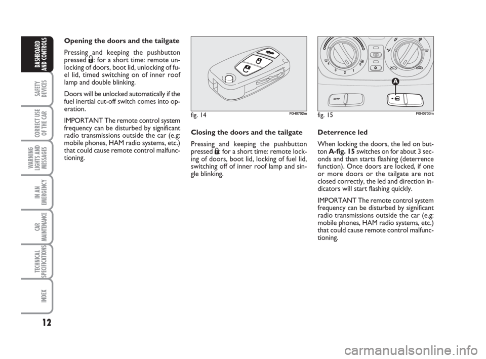
Opening the doors and the tailgate
Pressing and keeping the pushbutton
pressed
Ë: for a short time: remote un-
locking of doors, boot lid, unlocking of fu-
el lid, timed switching on of inner roof
lamp and double blinking.
Doors will be unlocked automatically if the
fuel inertial cut-off switch comes into op-
eration.
IMPORTANT The remote control system
frequency can be disturbed by significant
radio transmissions outside the car (e.g:
mobile phones, HAM radio systems, etc.)
that could cause remote control malfunc-
tioning.
fig. 14F0H0702m
Closing the doors and the tailgate
Pressing and keeping the pushbutton
pressed Á: for a short time: remote lock-
ing of doors, boot lid, locking of fuel lid,
switching off of inner roof lamp and sin-
gle blinking.Deterrence led
When locking the doors, the led on but-
ton A-fig. 15switches on for about 3 sec-
onds and than starts flashing (deterrence
function). Once doors are locked, if one
or more doors or the tailgate are not
closed correctly, the led and direction in-
dicators will start flashing quickly.
IMPORTANT The remote control system
frequency can be disturbed by significant
radio transmissions outside the car (e.g:
mobile phones, HAM radio systems, etc.)
that could cause remote control malfunc-
tioning.
fig. 15F0H0703m
001-035 idea GB 1 ed 10-07-2008 8:27 Pagina 12
Page 14 of 210
13
SAFETY
DEVICES
CORRECT USE
OF THE CAR
WARNING
LIGHTS AND
MESSAGES
IN AN
EMERGENCY
CAR
MAINTENANCE
TECHNICAL
SPECIFICATIONS
INDEX
DASHBOARD
AND CONTROLS
fig. 16F0H0702m
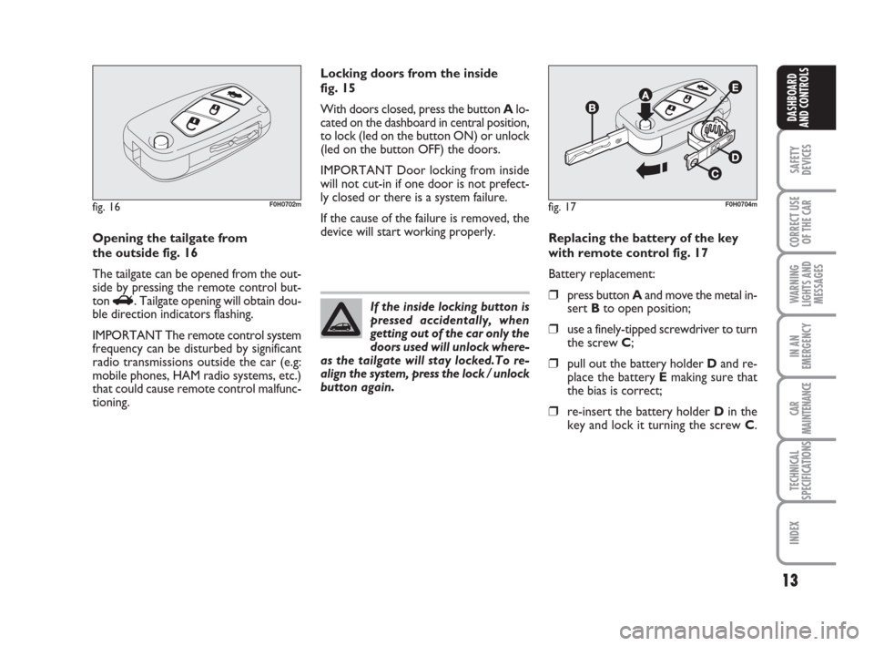
Opening the tailgate from
the outside fig. 16
The tailgate can be opened from the out-
side by pressing the remote control but-
ton
R. Tailgate opening will obtain dou-
ble direction indicators flashing.
IMPORTANT The remote control system
frequency can be disturbed by significant
radio transmissions outside the car (e.g:
mobile phones, HAM radio systems, etc.)
that could cause remote control malfunc-
tioning.Locking doors from the inside
fig. 15
With doors closed, press the button Alo-
cated on the dashboard in central position,
to lock (led on the button ON) or unlock
(led on the button OFF) the doors.
IMPORTANT Door locking from inside
will not cut-in if one door is not prefect-
ly closed or there is a system failure.
If the cause of the failure is removed, the
device will start working properly.
If the inside locking button is
pressed accidentally, when
getting out of the car only the
doors used will unlock where-
as the tailgate will stay locked.To re-
align the system, press the lock / unlock
button again.
fig. 17F0H0704m
Replacing the battery of the key
with remote control fig. 17
Battery replacement:
❒press button Aand move the metal in-
sert Bto open position;
❒use a finely-tipped screwdriver to turn
the screw C;
❒pull out the battery holder Dand re-
place the battery Emaking sure that
the bias is correct;
❒re-insert the battery holder Din the
key and lock it turning the screw C.
001-035 idea GB 1 ed 10-07-2008 8:27 Pagina 13
Page 29 of 210
28
SAFETY
DEVICES
CORRECT USE
OF THE CAR
WARNING
LIGHTS AND
MESSAGES
IN AN
EMERGENCY
CAR
MAINTENANCE
TECHNICAL
SPECIFICATIONS
INDEX
DASHBOARD
AND CONTROLS
Release of doors and tailgate (Key)
This function enables the release of the
front and rear doors, the release of the
driver's door only or the release of all the
doors including the tailgate.
To set the function, proceed as follows:
– press the MODEbutton for a short
time, the display shows “Open doors”,
“Op. drv.door” and “Open all”.
– press +or –to select; the selected item
will flash.
– Press MODEfor a short time to return
to the menu screen or press the button
for a longer time to return to the standard
screen without confirming the selection. – briefly press button MODE: the month
starts flashing on the display;
– press button +or –to set the month;
– briefly press button MODE: the day
starts flashing on the display;
– press button +or –to set the day.
NOTE The setting increases or decreas-
es by one unit each time button + or –
is pressed. Hold the button pressed to
start automatic quick increase/ decrease
of the setting. Complete the setting by
briefly pressing the button when the re-
quired setting is approached.
– briefly press button MODEto go back
to the menu screen or press the button
for a prolonged time to go back to the
standard screen without storing the set-
tings. 12h/24h clock mode
(Clock mode)
This function enables setting the screen to
either 12 or 24 hour mode.
Proceed as follows:
– briefly press button MODE: 12h or 24h
starts flashing on the display (depending
on the previously set parameter);
– press button +or –for selecting the de-
sired value;
– briefly press button MODEto go back
to the menu screen or press the button
for a prolonged time to go back to the
standard screen without storing the set-
tings.
Setting the date (Set Date)
This function enables updating the date
(year - month - day).
To update the date proceed as follows:
– briefly press button MODE: the year
starts flashing on the display;
– briefly press button +or –to set the
year;
001-035 idea GB 1 ed 10-07-2008 8:27 Pagina 28
Page 77 of 210
76
SAFETY
DEVICES
CORRECT USE
OF THE CAR
WARNING
LIGHTS AND
MESSAGES
IN AN
EMERGENCY
CAR
MAINTENANCE
TECHNICAL
SPECIFICATIONS
INDEX
DASHBOARD
AND CONTROLS
BOOT
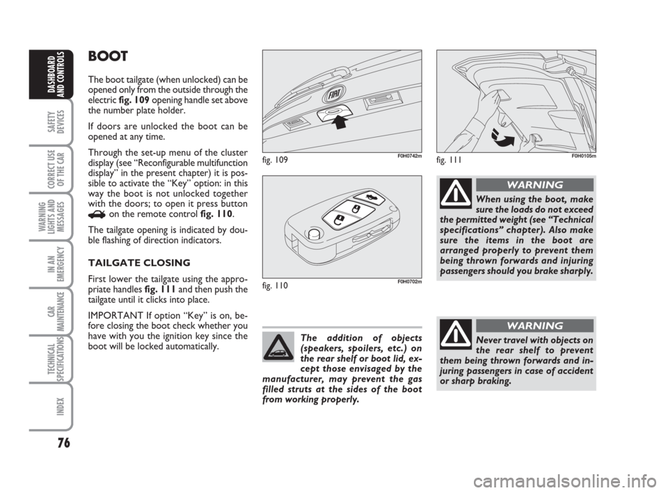
The boot tailgate (when unlocked) can be
opened only from the outside through the
electric fig. 109opening handle set above
the number plate holder.
If doors are unlocked the boot can be
opened at any time.
Through the set-up menu of the cluster
display (see “Reconfigurable multifunction
display” in the present chapter) it is pos-
sible to activate the “Key” option: in this
way the boot is not unlocked together
with the doors; to open it press button
Ron the remote control fig. 110.
The tailgate opening is indicated by dou-
ble flashing of direction indicators.
TAILGATE CLOSING
First lower the tailgate using the appro-
priate handles fig. 111and then push the
tailgate until it clicks into place.
IMPORTANT If option “Key” is on, be-
fore closing the boot check whether you
have with you the ignition key since the
boot will be locked automatically.
fig. 109F0H0742m
fig. 110F0H0702m
The addition of objects
(speakers, spoilers, etc.) on
the rear shelf or boot lid, ex-
cept those envisaged by the
manufacturer, may prevent the gas
filled struts at the sides of the boot
from working properly.
When using the boot, make
sure the loads do not exceed
the permitted weight (see “Technical
specifications” chapter). Also make
sure the items in the boot are
arranged properly to prevent them
being thrown forwards and injuring
passengers should you brake sharply.
WARNING
Never travel with objects on
the rear shelf to prevent
them being thrown forwards and in-
juring passengers in case of accident
or sharp braking.
WARNING
fig. 111F0H0105m
036-092 idea GB 1 ed 10-07-2008 16:12 Pagina 76
Page 78 of 210
77
SAFETY
DEVICES
CORRECT USE
OF THE CAR
WARNING
LIGHTS AND
MESSAGES
IN AN
EMERGENCY
CAR
MAINTENANCE
TECHNICAL
SPECIFICATIONS
INDEX
DASHBOARD
AND CONTROLS
EMERGENCY OPENING OF
TAILGATE
To succeed in opening the tailgate from
the inside, should the car battery be flat,
or because of a defect of the electric lock
of the tailgate, proceed as follows (refer
to “Extending the boot” in this section):
❒remove the rear head restraints;
❒tilt seat backrests to “table” configu-
ration;
❒tilt cushion / backrest completely.
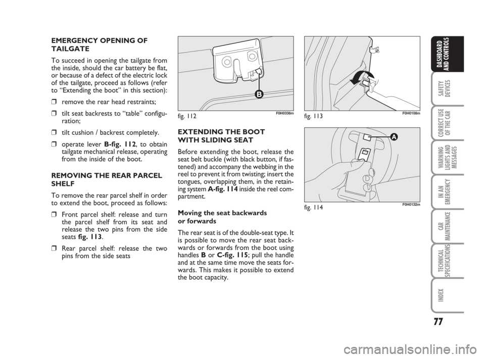
❒operate lever B-fig. 112, to obtain
tailgate mechanical release, operating
from the inside of the boot.
REMOVING THE REAR PARCEL
SHELF
To remove the rear parcel shelf in order
to extend the boot, proceed as follows:
❒Front parcel shelf: release and turn
the parcel shelf from its seat and
release the two pins from the side
seats fig. 113.
❒Rear parcel shelf: release the two
pins from the side seatsEXTENDING THE BOOT
WITH SLIDING SEAT
Before extending the boot, release the
seat belt buckle (with black button, if fas-
tened) and accompany the webbing in the
reel to prevent it from twisting; insert the
tongues, overlapping them, in the retain-
ing system A-fig. 114inside the reel com-
partment.
Moving the seat backwards
or forwards
The rear seat is of the double-seat type. It
is possible to move the rear seat back-
wards or forwards from the boot using
handles Bor C-fig. 115; pull the handle
and at the same time move the seats for-
wards. This makes it possible to extend
the boot capacity.
fig. 112F0H0338mfig. 113F0H0108m
fig. 114F0H0132m
036-092 idea GB 1 ed 10-07-2008 16:12 Pagina 77
Page 127 of 210
126
IN AN
EMERGENCY
CAR
MAINTENANCE
TECHNICAL
SPECIFICATIONS
INDEX
DASHBOARD
AND CONTROLS
SAFETY
DEVICES
CORRECT USE
OF THE CAR
WARNING
LIGHTS AND
MESSAGES
LOW ENGINE OIL
PRESSURE (red)
EXHAUSTED OIL (red)
(Multijet versions
with DPF)
Low engine oil pressure
When the ignition key is moved to MAR,
the warning light turns on and should go
out as soon as the engine is started.
The display will show the dedicated mes-
sage.
v
Exhausted oil
The warning light turns on and flashes
along with the message on the display
when the system detects that the engine
oil is exhausted.
After the first indication, at each engine
start-up, the warning light
vcontin-
ues to flash for about 60 seconds and then
every 2 hours until the oil is changed.“DUALDRIVE”
ELECTRIC POWER
STEERING FAILURE
(red)
When the ignition key is moved to MAR,
the warning light turns on and should go
off after a few seconds.
If the warning light stays on, the electric
steering system provides no assistance and
the effort on the steering wheel is in-
creased, although steering is still possible.
In this case, go to a Fiat Dealership.
The display will show the dedicated mes-
sage.
g
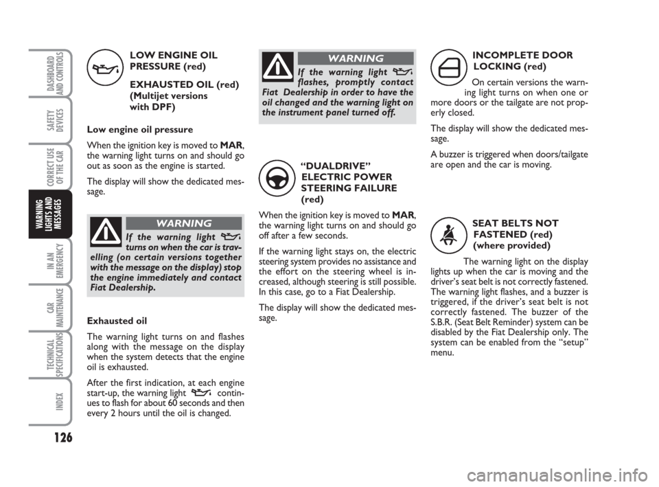
INCOMPLETE DOOR
LOCKING (red)
On certain versions the warn-
ing light turns on when one or
more doors or the tailgate are not prop-
erly closed.
The display will show the dedicated mes-
sage.
A buzzer is triggered when doors/tailgate
are open and the car is moving.
´
SEAT BELTS NOT
FASTENED (red)
(where provided)
The warning light on the display
lights up when the car is moving and the
driver’s seat belt is not correctly fastened.
The warning light flashes, and a buzzer is
triggered, if the driver’s seat belt is not
correctly fastened. The buzzer of the
S.B.R. (Seat Belt Reminder) system can be
disabled by the Fiat Dealership only. The
system can be enabled from the “setup”
menu.
with the message on the display) stop
the engine immediately and contact
Fiat Dealership.
WARNING
If the warning light vflashes, promptly contact
Fiat Dealership in order to have the
oil changed and the warning light on
the instrument panel turned off.
WARNING
123-132 idea GB 1 ed 10-07-2008 8:29 Pagina 126
Page 151 of 210
150
CAR
MAINTENANCE
TECHNICAL
SPECIFICATIONS
INDEX
DASHBOARD
AND CONTROLS
SAFETY
DEVICES
CORRECT USE
OF THE CAR
WARNING
LIGHTS AND
MESSAGES
IN AN
EMERGENCY
fig. 27F0H0187mfig. 28F0H0188m
REAR LIGHT UNITS
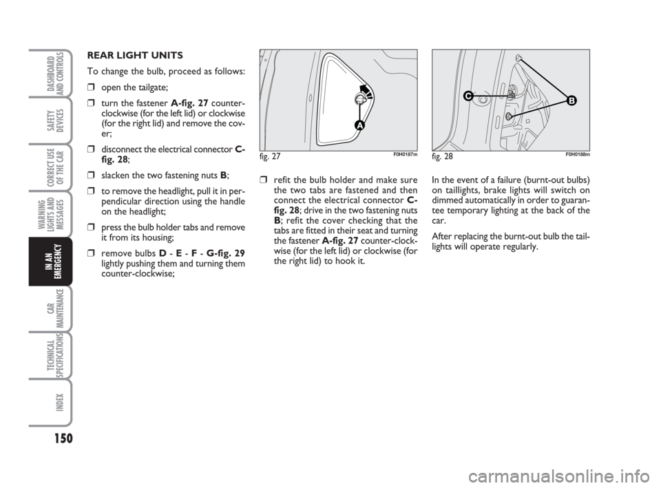
To change the bulb, proceed as follows:
❒open the tailgate;
❒turn the fastener A-fig. 27counter-
clockwise (for the left lid) or clockwise
(for the right lid) and remove the cov-
er;
❒disconnect the electrical connector C-
fig. 28;
❒slacken the two fastening nuts B;
❒to remove the headlight, pull it in per-
pendicular direction using the handle
on the headlight;
❒press the bulb holder tabs and remove
it from its housing;
❒remove bulbs D- E- F- G-fig. 29
lightly pushing them and turning them
counter-clockwise;
❒refit the bulb holder and make sure
the two tabs are fastened and then
connect the electrical connector C-
fig. 28; drive in the two fastening nuts
B; refit the cover checking that the
tabs are fitted in their seat and turning
the fastener A-fig. 27counter-clock-
wise (for the left lid) or clockwise (for
the right lid) to hook it. In the event of a failure (burnt-out bulbs)
on taillights, brake lights will switch on
dimmed automatically in order to guaran-
tee temporary lighting at the back of the
car.
After replacing the burnt-out bulb the tail-
lights will operate regularly.
133-160 idea GB 1 ed 10-07-2008 8:30 Pagina 150
Page 152 of 210
151
CAR
MAINTENANCE
TECHNICAL
SPECIFICATIONS
INDEX
DASHBOARD
AND CONTROLS
SAFETY
DEVICES
CORRECT USE
OF THE CAR
WARNING
LIGHTS AND
MESSAGES
IN AN
EMERGENCY
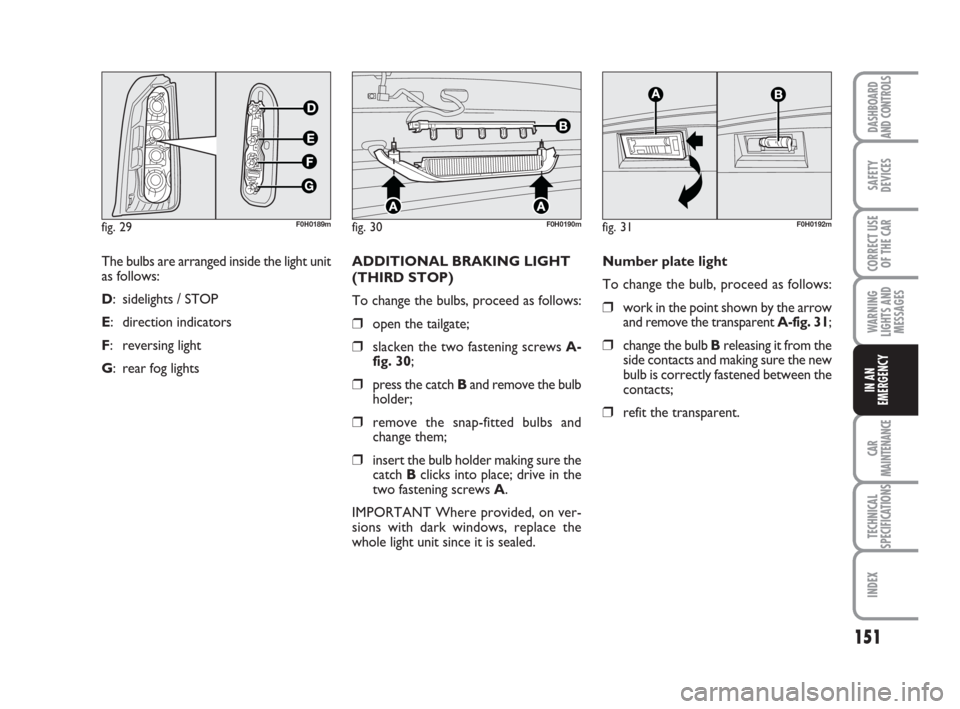
The bulbs are arranged inside the light unit
as follows:
D: sidelights / STOP
E: direction indicators
F: reversing light
G: rear fog lights
fig. 29F0H0189mfig. 30F0H0190m
ADDITIONAL BRAKING LIGHT
(THIRD STOP)
To change the bulbs, proceed as follows:
❒open the tailgate;
❒slacken the two fastening screws A-
fig. 30;
❒press the catch Band remove the bulb
holder;
❒remove the snap-fitted bulbs and
change them;
❒insert the bulb holder making sure the
catch Bclicks into place; drive in the
two fastening screws A.
IMPORTANT Where provided, on ver-
sions with dark windows, replace the
whole light unit since it is sealed.Number plate light
To change the bulb, proceed as follows:
❒work in the point shown by the arrow
and remove the transparent A-fig. 31;
❒change the bulb Breleasing it from the
side contacts and making sure the new
bulb is correctly fastened between the
contacts;
❒refit the transparent.
fig. 31F0H0192m
133-160 idea GB 1 ed 10-07-2008 8:30 Pagina 151
Page 153 of 210
152
CAR
MAINTENANCE
TECHNICAL
SPECIFICATIONS
INDEX
DASHBOARD
AND CONTROLS
SAFETY
DEVICES
CORRECT USE
OF THE CAR
WARNING
LIGHTS AND
MESSAGES
IN AN
EMERGENCY
IF AN INTERIOR LIGHT
BURNS OUT
For the type of bulb and power rating, see
“When needing to change a bulb”.
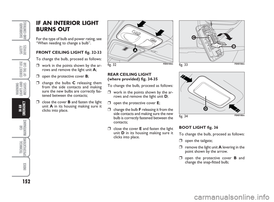
FRONT CEILING LIGHT fig. 32-33
To change the bulb, proceed as follows:
❒work in the points shown by the ar-
rows and remove the light unit A;
❒open the protective cover B;
❒change the bulbs Creleasing them
from the side contacts and making
sure the new bulbs are correctly fas-
tened between the contacts;
❒close the cover Band fasten the light
unit Ain its housing making sure it
clicks into place. REAR CEILING LIGHT
(where provided) fig. 34-35
To change the bulb, proceed as follows:
❒work in the points shown by the ar-
rows and remove the light unit D;
❒open the protective cover E;
❒change the bulb Freleasing it from the
side contacts and making sure the new
bulb is correctly fastened between the
contacts;
❒close the cover Eand fasten the light
unit Din its housing making sure it
clicks into place.
fig. 32F0H0193mfig. 33F0H0194m
fig. 34F0H0195m
BOOT LIGHT fig. 36
To change the bulb, proceed as follows:
❒open the tailgate;
❒remove the light unit Alevering in the
point shown by the arrow.
❒open the protective cover Band
change the snap-fitted bulb;
133-160 idea GB 1 ed 10-07-2008 8:30 Pagina 152