key FIAT LINEA 2007 1.G User Guide
[x] Cancel search | Manufacturer: FIAT, Model Year: 2007, Model line: LINEA, Model: FIAT LINEA 2007 1.GPages: 230, PDF Size: 3.31 MB
Page 19 of 230
18
SAFETY
DEVICES
CORRECT USE
OF THE
CAR
WARNING
LIGHTS AND
MESSAGES
IN AN
EMERGENCY
CAR
MAINTENANCE
TECHNICAL
SPECIFICATIONS
INDEX
DASHBOARD
AND CONTROLS
DIGITAL DISPLAY
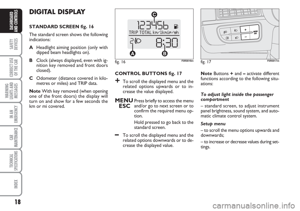
STANDARD SCREEN fig. 16
The standard screen shows the following
indications:
AHeadlight aiming position (only with
dipped beam headlights on).
BClock (always displayed, even with ig-
nition key removed and front doors
closed).
COdometer (distance covered in kilo-
metres or miles) and TRIP data.
NoteWith key removed (when opening
one of the front doors) the display will
turn on and show for a few seconds the
km or mi covered.CONTROL BUTTONS fig. 17
+To scroll the displayed menu and the
related options upwards or to in-
crease the value displayed.
MENU
ESCPress briefly to access the menu
and/or go to next screen or to
confirm the required menu op-
tion.
Hold pressed to go back to the
standard screen.
–To scroll the displayed menu and the
related options downwards or to de-
crease the displayed value. NoteButtons +and –activate different
functions according to the following situ-
ations:
To adjust light inside the passenger
compartment
– standard screen, to adjust instrument
panel brightness, sound system, and auto-
matic climate control system.
Setup menu
– to scroll the menu options upwards and
downwards;
– to increase or decrease values during set-
tings.
fig. 16F0R0016mfig. 17F0R0017m
Page 24 of 230
23
SAFETY
DEVICES
CORRECT USE
OF THE
CAR
WARNING
LIGHTS AND
MESSAGES
IN AN
EMERGENCY
CAR
MAINTENANCE
TECHNICAL
SPECIFICATIONS
INDEX
DASHBOARD
AND CONTROLS
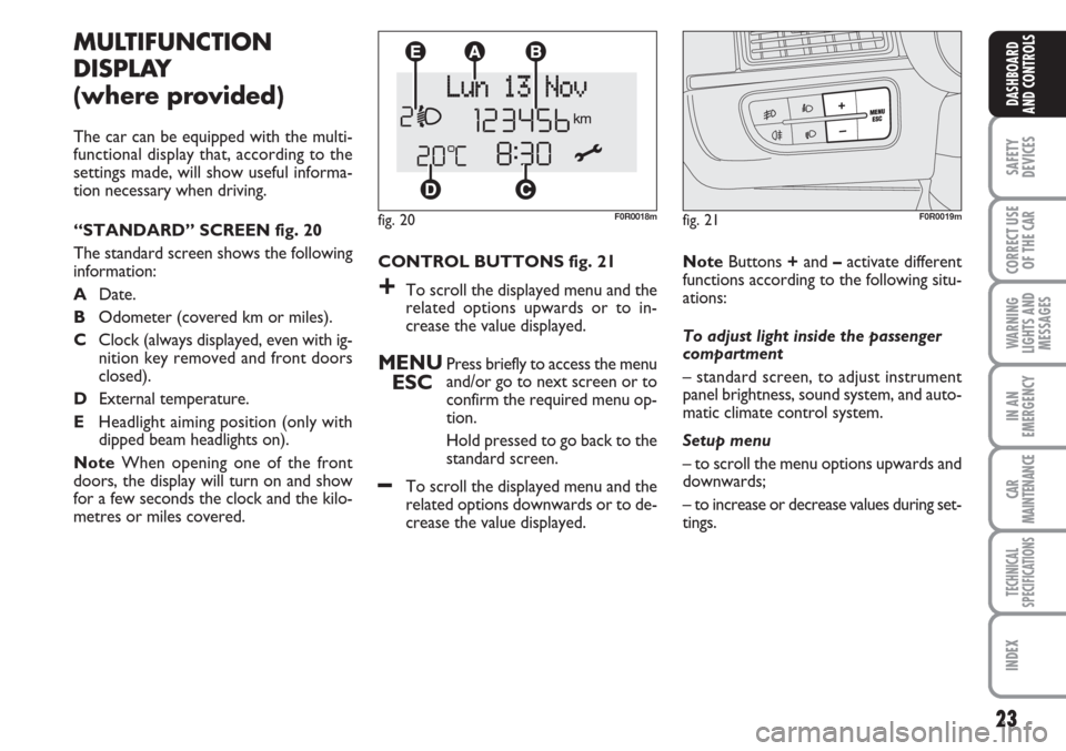
CONTROL BUTTONS fig. 21
+To scroll the displayed menu and the
related options upwards or to in-
crease the value displayed.
MENU
ESCPress briefly to access the menu
and/or go to next screen or to
confirm the required menu op-
tion.
Hold pressed to go back to the
standard screen.
–To scroll the displayed menu and the
related options downwards or to de-
crease the value displayed.
MULTIFUNCTION
DISPLAY
(where provided)
The car can be equipped with the multi-
functional display that, according to the
settings made, will show useful informa-
tion necessary when driving.
“STANDARD” SCREEN fig. 20
The standard screen shows the following
information:
ADate.
BOdometer (covered km or miles).
CClock (always displayed, even with ig-
nition key removed and front doors
closed).
DExternal temperature.
EHeadlight aiming position (only with
dipped beam headlights on).
NoteWhen opening one of the front
doors, the display will turn on and show
for a few seconds the clock and the kilo-
metres or miles covered.
fig. 20F0R0018m
NoteButtons +and –activate different
functions according to the following situ-
ations:
To adjust light inside the passenger
compartment
– standard screen, to adjust instrument
panel brightness, sound system, and auto-
matic climate control system.
Setup menu
– to scroll the menu options upwards and
downwards;
– to increase or decrease values during set-
tings.
fig. 21F0R0019m
Page 31 of 230
30
SAFETY
DEVICES
CORRECT USE
OF THE
CAR
WARNING
LIGHTS AND
MESSAGES
IN AN
EMERGENCY
CAR
MAINTENANCE
TECHNICAL
SPECIFICATIONS
INDEX
DASHBOARD
AND CONTROLS
Scheduled Servicing (Service)
Through this function it is possible to dis-
play information connected to proper car
servicing.
Proceed as follows:
– briefly press button MENU ESC: ser-
vice in km or mi, according to previous
setting, will be displayed (see paragraph
“Units”);
– briefly press button MENU ESCto go
back to the menu screen or press the but-
ton for long to go back to the standard
screen.NoteThe “Service Schedule” requires the
car to be serviced every 30,000 km (or
18,000 mi) or every 20,000 km (where
provided); this indication will appear au-
tomatically with the key at MARwhen
there are 2000 km left (or 1240 mi) and
will be presented automatically every 200
km (or 124 mi). The indications will ap-
pear more frequently where there are 200
km left. The indication will appear in kilo-
metres or miles according to the settings.
When the next scheduled service opera-
tion is approaching, the message “Service”
will appear on the display followed by the
number of kilometres or miles left when
the key is turned to MAR. Go to a Fiat
Dealership where the “Scheduled Service”
operations will be performed and the mes-
sage will be reset. Adjusting the button volume
(Button Vol.)
This function may be used to adjust the
volume of the beep accompanying the ac-
tivation of buttons MENU ESC, +and
–can be adjusted according to 8 levels.
To adjust the volume proceed as follows:
– briefly press button MENU ESC: the
previously set volume “level” will flash on
the display;
– press button +or –for setting;
– briefly press button MENU ESCto go
back to the menu screen or press the but-
ton for long to go back to the standard
screen without storing settings.
Page 33 of 230
32
SAFETY
DEVICES
CORRECT USE
OF THE
CAR
WARNING
LIGHTS AND
MESSAGES
IN AN
EMERGENCY
CAR
MAINTENANCE
TECHNICAL
SPECIFICATIONS
INDEX
DASHBOARD
AND CONTROLS
RECONFIGURABLE
MULTIFUNCTION
DISPLAY
(where provided)
The car may be equipped with reconfig-
urable a multifunctional display that, ac-
cording to the settings made, will show
useful driving information.
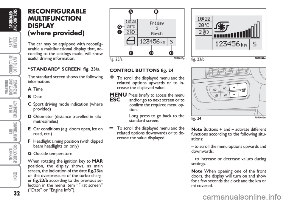
“STANDARD” SCREEN fig. 23/a
The standard screen shows the following
information:
ATime
BDate
CSport driving mode indication (where
provided)
DOdometer (distance travelled in kilo-
metres/miles)
ECar conditions (e.g. doors open, ice on
road, etc.)
FHeadlight aiming position (with dipped
beam headlights on only)
GOutside temperature
When rotating the ignition key to MAR
position, the display shows, as main
screen, the indication of the date fig.23/a
or the overpressure of the turbo-charg-
er fig.23/baccording to the previous se-
lection in the menu item “First screen”
(“Date” or “Engine Info”).CONTROL BUTTONS fig. 24
+To scroll the displayed menu and the
related options upwards or to in-
crease the displayed value.
MENU Press briefly to access the menuESCand/or go to next screen or to
confirm the required menu op-
tion.
Long press to go back to the
standard screen.
–To scroll the displayed menu and the
related options downwards or to de-
crease the value displayed. NoteButtons +and –activate different
functions according to the following situ-
ations:
– to scroll the menu options upwards and
downwards;
– to increase or decrease values during
settings.
NoteWhen opening one of the front
doors, the display will turn on and show
for a few seconds the clock and the km or
mi covered.
fig. 24F0R0019m
fig. 23/aF0R2010gfig. 23/bF0R0241m
Page 38 of 230
37
SAFETY
DEVICES
CORRECT USE
OF THE
CAR
WARNING
LIGHTS AND
MESSAGES
IN AN
EMERGENCY
CAR
MAINTENANCE
TECHNICAL
SPECIFICATIONS
INDEX
DASHBOARD
AND CONTROLS
Note The setting will increase or de-
crease by one unit each time +or –is
pressed. Hold the button pressed to in-
crease/decrease the setting rapidly. Com-
plete the setting by briefly pressing the
button when you approach the required
setting.
– when accessing the “Format” submenu:
briefly press button MENU ESC: the
previously set display format will flash on
the display;
– press button +or –to select “24h” or
“12h”.
When you have made the required set-
tings, briefly press button MENU ESCto
go back to the menu screen or press the
button for long to go back to the standard
screen without storing settings.
– hold MENU ESCpressed to go back
to the standard screen or main menu ac-
cording to the points of the menu where
you are at.Set date (Set Date)
This function may be used to update the
date (year - month - day).
To correct the date proceed as follows:
– briefly press button MENU ESC:
“year” will flash on the display;
– press button +or –for setting;
– briefly press button MENU ESC:
“month” will flash on the display;
– press button +or –for setting;
– briefly press button MENU ESC: “day”
will flash on the display;
– press button +or –for setting.
Note The setting will increase or de-
crease by one unit each time +or –is
pressed. Hold the button pressed to in-
crease/decrease the setting rapidly. Com-
plete the setting by briefly pressing the
button when you approach the required
setting.
– briefly press button MENU ESCto go
back to the menu screen or press the but-
ton for long to go back to the standard
screen without storing settings.First screen (information displayed
in the main screen)
(where provided)
This function enables to select the type of
information displayed in the main screen.
It is possible to display the date or the
pressure of the turbo-compressor.
To select one of the two items, proceed
as follows:
– push the button MENU ESCfor a
short time, “First screen” is displayed;
– press again the button MENU ESCfor
a short time to display the “Date” and
“Engine Info” options;
– press +or –to select the type of infor-
mation to be displayed in the main screen;
– press MENU ESCfor a short time to
store the selection and return to the pre-
vious screen or press the button for a
longer time to return to the standard
screen without storing the selection.
Rotating the ignition key on MAR, the re-
configurable multifunctional display, after
the start-up check, displays the previous-
ly set information using the “First screen”
function of the menu.
Page 41 of 230
40
SAFETY
DEVICES
CORRECT USE
OF THE
CAR
WARNING
LIGHTS AND
MESSAGES
IN AN
EMERGENCY
CAR
MAINTENANCE
TECHNICAL
SPECIFICATIONS
INDEX
DASHBOARD
AND CONTROLS
Button volume
(Button volume adjustment)
This function may be used to adjust the
volume of the beep accompanying the ac-
tivation of buttons MENU ESC, +and
–can be adjusted according to 8 levels.
To adjust the volume proceed as follows:
– briefly press button MENU ESC: the
previously set volume “level” will flash on
the display;
– press button +or –for setting;
– briefly press button MENU ESCto go
back to the menu screen or press the but-
ton for long to go back to the standard
screen without storing settings.
Belt buzzer (Buzzer activation
for S.B.R. indication)
This function can be only displayed after
Fiat Dealership has deactivated the S.B.R.
system (see paragraph “S.B.R. system” in
section “Safety devices”).Service (Scheduled servicing)
This function may be used to display in-
formation connected to proper car ser-
vicing.
Proceed as follows:
– briefly press button MENU ESC: ser-
vice in km or mi, according to previous set-
ting, will be displayed (see paragraph
“Units”);
– briefly press button MENU ESCto go
back to the menu screen or press the but-
ton for long to go back to the standard
screen.NoteThe “Service Schedule” requires the
car to be serviced every 30,000 km (or
18,000 mi) or every 20,000 km (12,000 mi)
(where provided); this indication will ap-
pear automatically with the key at MAR
when there are 2000 km left (or equiva-
lent distance in miles) and will be pre-
sented automatically every 200 km (or
equivalent distance in miles). The indica-
tions will appear more frequently where
there are 200 km left. The indication will
appear in kilometres or miles according to
the settings. When the next scheduled
service operation is approaching, the mes-
sage “Service” will appear on the display
followed by the number of kilometres or
miles left when the key is turned to MAR.
Go to a Fiat Dealership where the “Sched-
uled Service” operations will be per-
formed and the message will be reset.
Page 43 of 230
42
SAFETY
DEVICES
CORRECT USE
OF THE
CAR
WARNING
LIGHTS AND
MESSAGES
IN AN
EMERGENCY
CAR
MAINTENANCE
TECHNICAL
SPECIFICATIONS
INDEX
DASHBOARD
AND CONTROLS
TRIP COMPUTER
General features
The “Trip computer” is used to display in-
formation on car operation when the key
is turned to MAR. This function allows to
define two separate trips called “Trip A”
and “Trip B” for monitoring the car’s
“complete mission” in a reciprocally in-
dependent manner.
Both functions are resettable (reset - start
of new mission).
“Trip A” may be used to display the fig-
ures relating to:
– Range
– Distance travelled
– Average consumption
– Instant consumption
– Average speed
– Travel time (driving time).“Trip B”, available on multifunctional dis-
play only, shall be used to display the fig-
ures relating to:
– Trip distance B
– Average consumption B
– Average speed B
– Travel time B (driving time).
Note“Trip B” functions may be exclud-
ed (see “Trip B on”). “Range” and “In-
stantaneous consumption” cannot be re-
set.Values displayed
Range
This indicates the distance which may be
travelled with the fuel in the tank
assuming that driving conditions will not
change. The message “——” will appear
on the display in the following cases:
– range shorter than 50 km (or 30 mi)
– car left parked with engine running for
long.
Distance travelled
This indicates the distance covered from
the start of the new mission.
Page 44 of 230
43
SAFETY
DEVICES
CORRECT USE
OF THE
CAR
WARNING
LIGHTS AND
MESSAGES
IN AN
EMERGENCY
CAR
MAINTENANCE
TECHNICAL
SPECIFICATIONS
INDEX
DASHBOARD
AND CONTROLS
Average consumption
This indicates the average consumption
from the start of the new mission.
Instant consumption
This indicates the fuel consumption. The
value is constantly updated. The message
“----” will appear on the display
if the car is parked with the engine run-
ning.
Average speed
This shows the car average speed as a
function of the overall time elapsed since
the start of the new mission.
Travel time
This value shows the time elapsed since
the start of the new mission.
IMPORTANT If information is not avail-
able, the message “----” will appear instead
of the Trip Computer values. Displaying
of the values will be resumed when nor-
mal operation is restored without reset-
ting the values displayed before the prob-
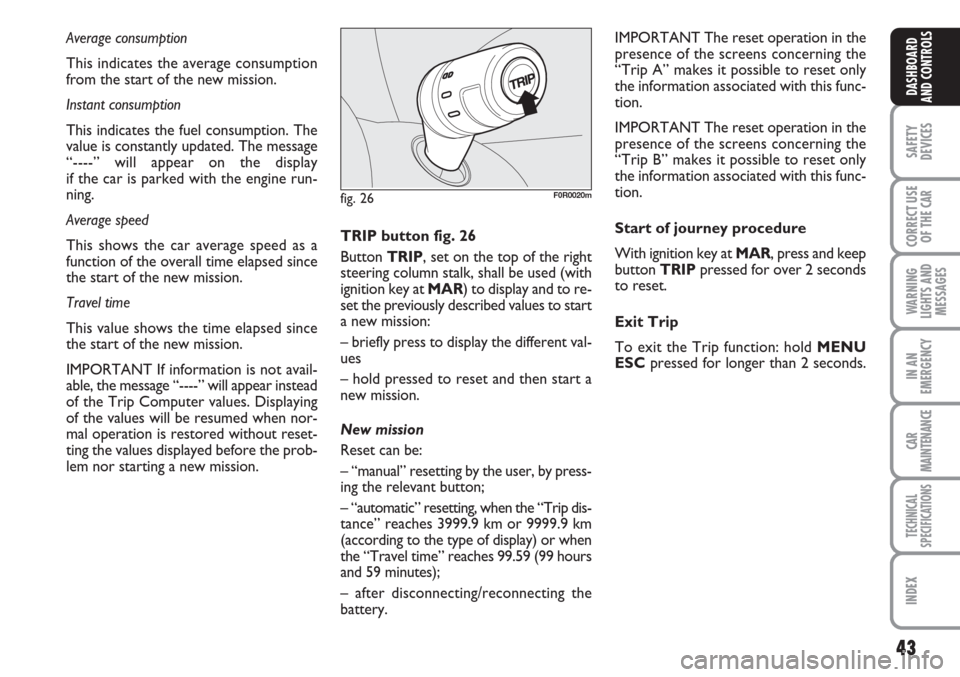
lem nor starting a new mission. TRIP button fig. 26
Button TRIP, set on the top of the right
steering column stalk, shall be used (with
ignition key at MAR) to display and to re-
set the previously described values to start
a new mission:
– briefly press to display the different val-
ues
– hold pressed to reset and then start a
new mission.
New mission
Reset can be:
– “manual” resetting by the user, by press-
ing the relevant button;
– “automatic” resetting, when the “Trip dis-
tance” reaches 3999.9 km or 9999.9 km
(according to the type of display) or when
the “Travel time” reaches 99.59 (99 hours
and 59 minutes);
– after disconnecting/reconnecting the
battery.IMPORTANT The reset operation in the
presence of the screens concerning the
“Trip A” makes it possible to reset only
the information associated with this func-
tion.
IMPORTANT The reset operation in the
presence of the screens concerning the
“Trip B” makes it possible to reset only
the information associated with this func-
tion.
Start of journey procedure
With ignition key at MAR, press and keep
button TRIPpressed for over 2 seconds
to reset.
Exit Trip
To exit the Trip function: hold MENU
ESCpressed for longer than 2 seconds.
fig. 26F0R0020m
Page 49 of 230
48
SAFETY
DEVICES
CORRECT USE
OF THE
CAR
WARNING
LIGHTS AND
MESSAGES
IN AN
EMERGENCY
CAR
MAINTENANCE
TECHNICAL
SPECIFICATIONS
INDEX
DASHBOARD
AND CONTROLS
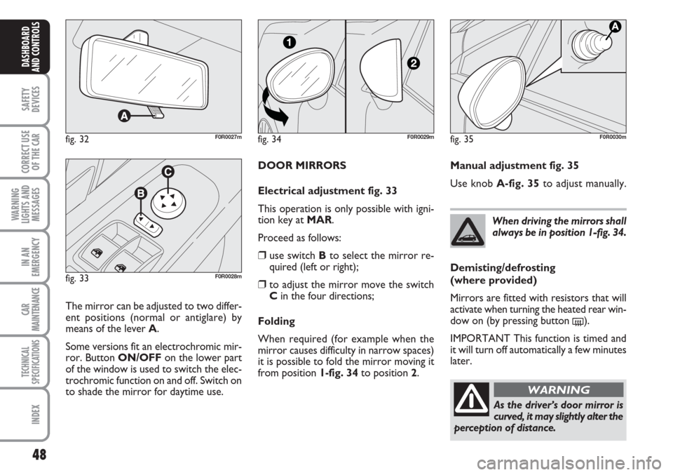
DOOR MIRRORS
Electrical adjustment fig. 33
This operation is only possible with igni-
tion key at MAR.
Proceed as follows:
❒use switch Bto select the mirror re-
quired (left or right);
❒to adjust the mirror move the switch
Cin the four directions;
Folding
When required (for example when the
mirror causes difficulty in narrow spaces)
it is possible to fold the mirror moving it
from position 1-fig. 34 to position 2.
fig. 32F0R0027m
fig. 33F0R0028m
The mirror can be adjusted to two differ-
ent positions (normal or antiglare) by
means of the lever A.
Some versions fit an electrochromic mir-
ror. Button ON/OFFon the lower part
of the window is used to switch the elec-
trochromic function on and off. Switch on
to shade the mirror for daytime use.When driving the mirrors shall
always be in position 1-fig. 34.
As the driver’s door mirror is
curved, it may slightly alter the
perception of distance.
WARNING
fig. 34F0R0029mfig. 35F0R0030m
Manual adjustment fig. 35
Use knob A-fig. 35to adjust manually.
Demisting/defrosting
(where provided)
Mirrors are fitted with resistors that will
activate when turning the heated rear win-
dow on (by pressing button
().
IMPORTANT This function is timed and
it will turn off automatically a few minutes
later.
Page 67 of 230
66
SAFETY
DEVICES
CORRECT USE
OF THE
CAR
WARNING
LIGHTS AND
MESSAGES
IN AN
EMERGENCY
CAR
MAINTENANCE
TECHNICAL
SPECIFICATIONS
INDEX
DASHBOARD
AND CONTROLS
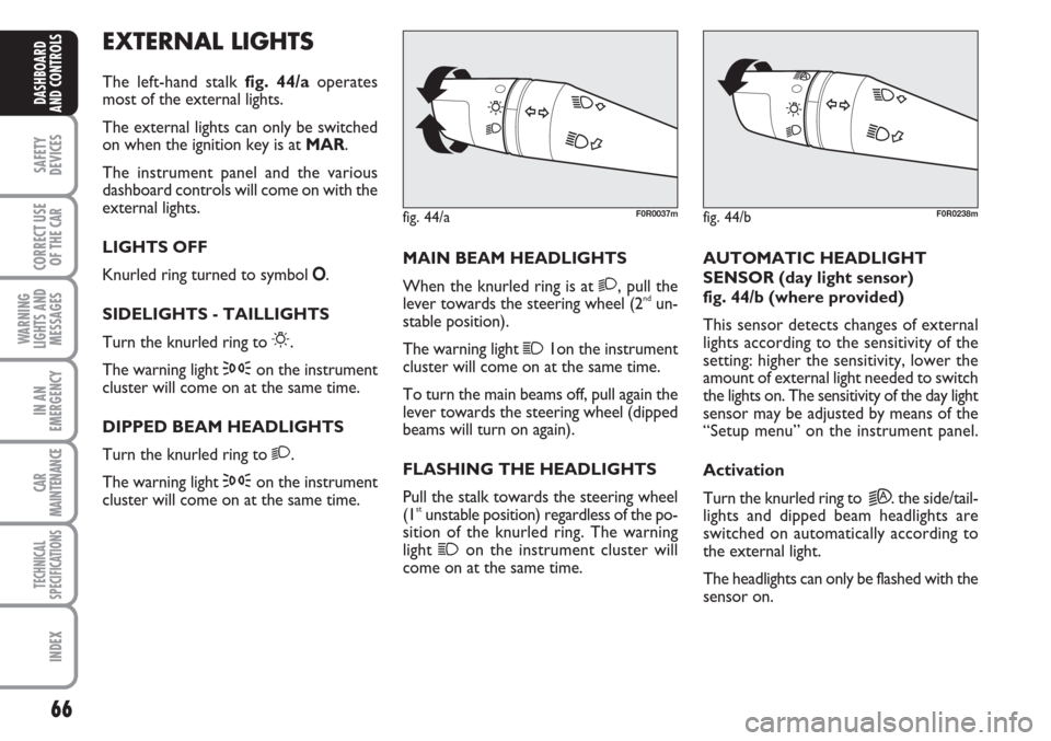
EXTERNAL LIGHTS
The left-hand stalk fig. 44/aoperates
most of the external lights.
The external lights can only be switched
on when the ignition key is at MAR.
The instrument panel and the various
dashboard controls will come on with the
external lights.
LIGHTS OFF
Knurled ring turned to symbol O.
SIDELIGHTS - TAILLIGHTS
Turn the knurled ring to
6.
The warning light
3on the instrument
cluster will come on at the same time.
DIPPED BEAM HEADLIGHTS
Turn the knurled ring to
2.
The warning light
3on the instrument
cluster will come on at the same time.MAIN BEAM HEADLIGHTS
When the knurled ring is at
2, pull the
lever towards the steering wheel (2ndun-
stable position).
The warning light
11on the instrument
cluster will come on at the same time.
To turn the main beams off, pull again the
lever towards the steering wheel (dipped
beams will turn on again).
FLASHING THE HEADLIGHTS
Pull the stalk towards the steering wheel
(1
stunstable position) regardless of the po-
sition of the knurled ring. The warning
light
1on the instrument cluster will
come on at the same time.AUTOMATIC HEADLIGHT
SENSOR (day light sensor)
fig. 44/b (where provided)
This sensor detects changes of external
lights according to the sensitivity of the
setting: higher the sensitivity, lower the
amount of external light needed to switch
the lights on. The sensitivity of the day light
sensor may be adjusted by means of the
“Setup menu” on the instrument panel.
Activation
Turn the knurled ring to
2A. the side/tail-
lights and dipped beam headlights are
switched on automatically according to
the external light.
The headlights can only be flashed with the
sensor on.
fig. 44/aF0R0037mfig. 44/bF0R0238m