Disc FIAT LINEA 2007 1.G Owners Manual
[x] Cancel search | Manufacturer: FIAT, Model Year: 2007, Model line: LINEA, Model: FIAT LINEA 2007 1.GPages: 230, PDF Size: 3.31 MB
Page 44 of 230
43
SAFETY
DEVICES
CORRECT USE
OF THE
CAR
WARNING
LIGHTS AND
MESSAGES
IN AN
EMERGENCY
CAR
MAINTENANCE
TECHNICAL
SPECIFICATIONS
INDEX
DASHBOARD
AND CONTROLS
Average consumption
This indicates the average consumption
from the start of the new mission.
Instant consumption
This indicates the fuel consumption. The
value is constantly updated. The message
“----” will appear on the display
if the car is parked with the engine run-
ning.
Average speed
This shows the car average speed as a
function of the overall time elapsed since
the start of the new mission.
Travel time
This value shows the time elapsed since
the start of the new mission.
IMPORTANT If information is not avail-
able, the message “----” will appear instead
of the Trip Computer values. Displaying
of the values will be resumed when nor-
mal operation is restored without reset-
ting the values displayed before the prob-
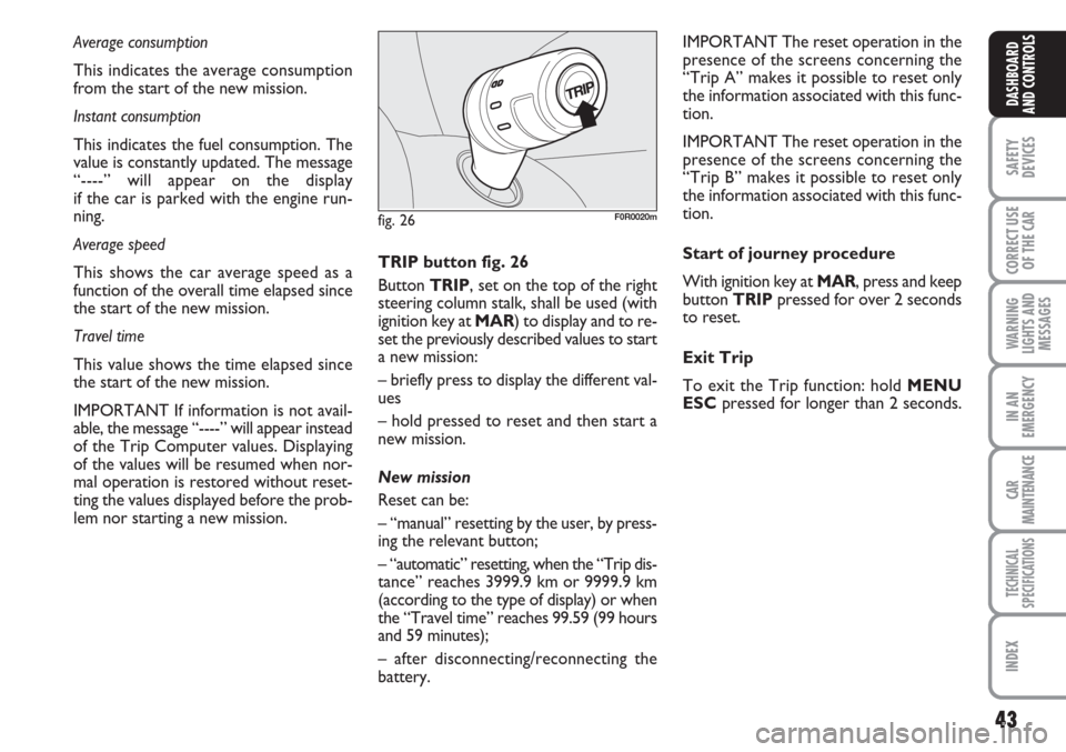
lem nor starting a new mission. TRIP button fig. 26
Button TRIP, set on the top of the right
steering column stalk, shall be used (with
ignition key at MAR) to display and to re-
set the previously described values to start
a new mission:
– briefly press to display the different val-
ues
– hold pressed to reset and then start a
new mission.
New mission
Reset can be:
– “manual” resetting by the user, by press-
ing the relevant button;
– “automatic” resetting, when the “Trip dis-
tance” reaches 3999.9 km or 9999.9 km
(according to the type of display) or when
the “Travel time” reaches 99.59 (99 hours
and 59 minutes);
– after disconnecting/reconnecting the
battery.IMPORTANT The reset operation in the
presence of the screens concerning the
“Trip A” makes it possible to reset only
the information associated with this func-
tion.
IMPORTANT The reset operation in the
presence of the screens concerning the
“Trip B” makes it possible to reset only
the information associated with this func-
tion.
Start of journey procedure
With ignition key at MAR, press and keep
button TRIPpressed for over 2 seconds
to reset.
Exit Trip
To exit the Trip function: hold MENU
ESCpressed for longer than 2 seconds.
fig. 26F0R0020m
Page 86 of 230
85
SAFETY
DEVICES
CORRECT USE
OF THE
CAR
WARNING
LIGHTS AND
MESSAGES
IN AN
EMERGENCY
CAR
MAINTENANCE
TECHNICAL
SPECIFICATIONS
INDEX
DASHBOARD
AND CONTROLS
Power window system initialisation
Safety system shall be re-initialised after
disconnecting the battery or if the rele-
vant protection fuse is blown.
Initialisation procedure:
❒fully close manually the window to ini-
tialise;
❒rafter the window has reached the up-
per end of travel, hold the up button
pressed for at least one second.
Incorrect use of the power
windows may be dangerous.
Before operation, always check that
no-one is exposed to the risk of being
injured by directly by the moving win-
dow or objects getting caught and
dragged. When leaving the car, al-
ways remove the key from the igni-
tion device to avoid the risk of injury
due to accidental operation of the
power windows.
WARNING
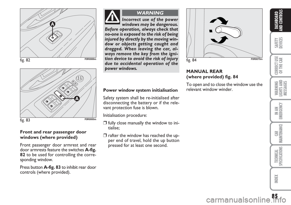
Front and rear passenger door
windows (where provided)
Front passenger door armrest and rear
door armrests feature the switches A-fig.
82to be used for controlling the corre-
sponding window.
Press button A-fig. 83to inhibit rear door
controls (where provided).MANUAL REAR
(where provided) fig. 84
To open and to close the window use the
relevant window winder.
fig. 84F0R0070mfig. 82F0R0069m
fig. 83F0R0000m
Page 91 of 230
90
SAFETY
DEVICES
CORRECT USE
OF THE
CAR
WARNING
LIGHTS AND
MESSAGES
IN AN
EMERGENCY
CAR
MAINTENANCE
TECHNICAL
SPECIFICATIONS
INDEX
DASHBOARD
AND CONTROLS
The bonnet must always be
perfectly closed while trav-
elling for reasons of safety. Make sure
that the bonnet is perfectly closed
and that the lock is engaged. If you
discover that the bonnet is not per-
fectly closed while travelling, stop im-
mediately and close the bonnet in the
correct manner.
WARNING
The bonnet may drop sud-
denly if the supporting rod is
not in correct position.
WARNING
Perform these operations
when the car is stationary
only.
WARNING
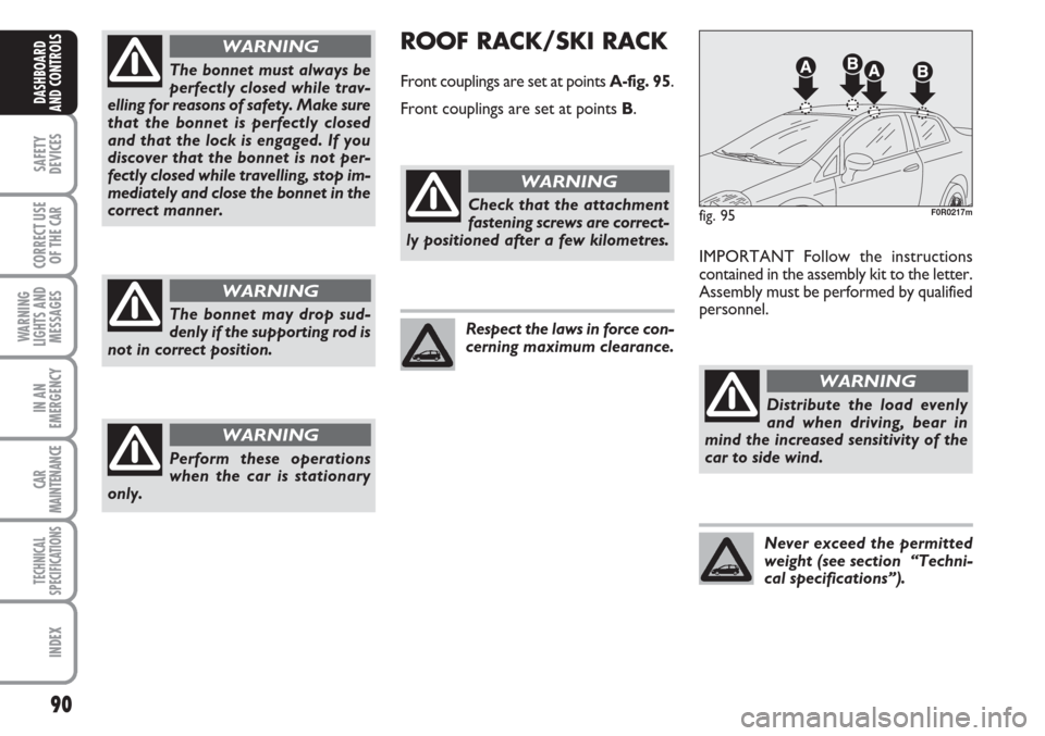
ROOF RACK/SKI RACK
Front couplings are set at points A-fig. 95.
Front couplings are set at points B.
IMPORTANT Follow the instructions
contained in the assembly kit to the letter.
Assembly must be performed by qualified
personnel.
fig. 95F0R0217mCheck that the attachment
fastening screws are correct-
ly positioned after a few kilometres.
WARNING
Respect the laws in force con-
cerning maximum clearance.
Distribute the load evenly
and when driving, bear in
mind the increased sensitivity of the
car to side wind.
WARNING
Never exceed the permitted
weight (see section “Techni-
cal specifications”).
Page 93 of 230
92
SAFETY
DEVICES
CORRECT USE
OF THE
CAR
WARNING
LIGHTS AND
MESSAGES
IN AN
EMERGENCY
CAR
MAINTENANCE
TECHNICAL
SPECIFICATIONS
INDEX
DASHBOARD
AND CONTROLS
ABS SYSTEM
If you have never driven a car with ABS be-
fore, it is advisable to perform a few tests
on slippery ground, naturally in conditions
of safety and respecting the Highway Code
of the country where you are driving. Read
the following information carefully.
The car is fitted with an ABS braking sys-
tem, which prevents the wheels from lock-
ing when braking, makes the most of road
grip and gives the best control when emer-
gency braking under difficulty road condi-
tions.
System is completed by EBD (Electronic
Braking force Distribution), which dis-
tributes the braking action between front
and rear wheels.
IMPORTANT Maximum efficiency of the
braking system is obtained after approxi-
mately 500 km (when the car is new or af-
ter replacing the brake pads/discs): during
this time, avoid sudden, repeated and pro-
longed braking.The ABS exploits the tyre-
road grip at the best, but it
cannot improve it; you should there-
fore take every care when driving on
slippery surfaces without taking un-
necessary risks.
WARNING
ABS SYSTEM INTERVENTION
Intervention of the ABS is detected by a
slight pulsing of the brake pedal accompa-
nied by noise: such an event indicates that
you need to adjust your speed to the type
of road on which you are travelling.
When the ABS intervenes it
means that you are ap-
proaching the grip limit between tyres
and road: slow down to exploit all the
available grip.
WARNING
FAILURE INDICATIONS
ABS failure
ABS failure is indicated by the turning on
of warning light
>on the instrument pan-
el together with the dedicated message on
the multifunctional display (where pro-
vided), (see section “Warning lights and
messages”).
In the case, the braking system will work
as normal without the extra potentials of-
fered by the ABS system. Drive carefully
to the nearest Fiat Dealership to have the
system checked.
Page 103 of 230
102
SAFETY
DEVICES
CORRECT USE
OF THE
CAR
WARNING
LIGHTS AND
MESSAGES
IN AN
EMERGENCY
CAR
MAINTENANCE
TECHNICAL
SPECIFICATIONS
INDEX
DASHBOARD
AND CONTROLS
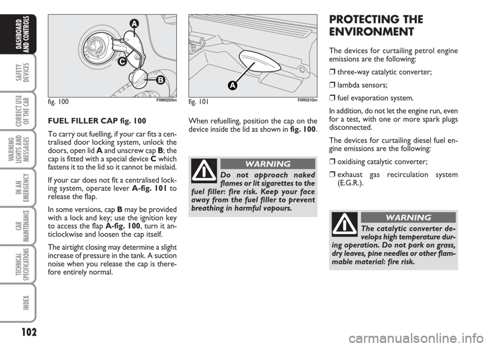
FUEL FILLER CAP fig. 100
To carry out fuelling, if your car fits a cen-
tralised door locking system, unlock the
doors, open lid Aand unscrew cap B; the
cap is fitted with a special device Cwhich
fastens it to the lid so it cannot be mislaid.
If your car does not fit a centralised lock-
ing system, operate lever A-fig. 101to
release the flap.
In some versions, cap Bmay be provided
with a lock and key; use the ignition key
to access the flap A-fig. 100, turn it an-
ticlockwise and loosen the cap itself.
The airtight closing may determine a slight
increase of pressure in the tank. A suction
noise when you release the cap is there-
fore entirely normal.
PROTECTING THE
ENVIRONMENT
The devices for curtailing petrol engine
emissions are the following:
❒three-way catalytic converter;
❒lambda sensors;
❒fuel evaporation system.
In addition, do not let the engine run, even
for a test, with one or more spark plugs
disconnected.
The devices for curtailing diesel fuel en-
gine emissions are the following:
❒oxidising catalytic converter;
❒exhaust gas recirculation system
(E.G.R.).
fig. 100F0M0203m
Do not approach naked
flames or lit sigarettes to the
fuel filler: fire risk. Keep your face
away from the fuel filler to prevent
breathing in harmful vapours.
WARNING
fig. 101F0R0210m
When refuelling, position the cap on the
device inside the lid as shown in fig. 100.
The catalytic converter de-
velops high temperature dur-
ing operation. Do not park on grass,
dry leaves, pine needles or other flam-
mable material: fire risk.
WARNING
Page 133 of 230
132
WARNING
LIGHTS AND
MESSAGES
IN AN
EMERGENCY
CAR
MAINTENANCE
TECHNICAL
SPECIFICATIONS
INDEX
DASHBOARD
AND CONTROLS
SAFETY
DEVICES
CORRECT USE
OF THE CAR
CAR INACTIVITY
If the car is to be left inactive for longer
than a month, the following precautions
should be noted:
❒park the car in covered, dry and if pos-
sible well-ventilated premises;
❒engage a gear;
❒check that the handbrake is not en-
gaged;
❒disconnect the negative battery termi-
nal and check battery charge (see para-
graph “Charge level check” in chapter
“Maintenance and care”). Repeat this
check once every three months dur-
ing storage. Recharge the battery if nec-
essary (see paragraph “If the battery is
flat” in chapter “In an emergency”);
❒clean and protect the painted parts us-
ing protective wax;
❒clean and protect the shiny metal parts
using special compounds readily avail-
able;
❒sprinkle talcum powder on the rubber
windscreen and rear window wiper
blades and lift them off the glass;
❒slightly open the windows;
❒cover the car with a fabric or perfo-
rated plastic terrapin. Do not use com-
pact plastic sheets which do not allow
humidity to evaporate from the surface
of the car;
❒inflate tyres to +0.5 bar above the nor-
mal specified pressure and check it at
intervals;
❒if you don’t disconnect the battery from
the electric system, check its charge
every month (see paragraph “Charge
level check” in chapter “Maintenance
and care”);
❒recharge the battery if necessary (see
paragraph “If the battery is flat” in chap-
ter “In an emergency”);
❒do not drain the engine cooling system.
IMPORTANT Where relevant, switch off
the car alarm with the remote control.
Keep your speed down when
snow chains are fitted. Do
not exceed 50 km/h. Avoid
potholes, steps and pave-
ments and avoid also to dri-
ve for long distances on
roads not covered with snow to pre-
vent damaging the car and the
roadbed.
WARNING
Chains cannot be applied to
tyre 205/45 R17 88V.
WARNING
Page 147 of 230
146
WARNING
LIGHTS AND
MESSAGES
CAR
MAINTENANCE
TECHNICAL
SPECIFICATIONS
IINDEX
DASHBOARD
AND CONTROLS
SAFETY
DEVICES
CORRECT USE
OF THE
CAR
IN AN
EMERGENCY
STARTING THE
ENGINE
EMERGENCY START-UP
Go to a Fiat Dealership immediately if in-
strument panel warning light
Ycomes
on steady.
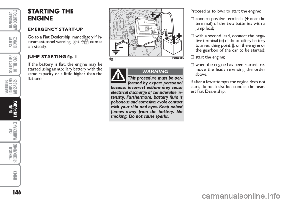
JUMP STARTING fig. 1
If the battery is flat, the engine may be
started using an auxiliary battery with the
same capacity or a little higher than the
flat one. Proceed as follows to start the engine:
❒connect positive terminals (+near the
terminal) of the two batteries with a
jump lead;
❒with a second lead, connect the nega-
tive terminal (–) of the auxiliary battery
to an earthing point
Eon the engine or
the gearbox of the car to be started;
❒start the engine;
❒when the engine has been started, re-
move the leads reversing the order
above.
If after a few attempts the engine does not
start, do not insist but contact the near-
est Fiat Dealership.
This procedure must be per-
formed by expert personnel
because incorrect actions may cause
electrical discharge of considerable in-
tensity. Furthermore, battery fluid is
poisonous and corrosive: avoid contact
with your skin and eyes. Keep naked
flames away from the battery. No
smoking. Do not cause sparks.
WARNING
fig. 1F0R0242m
Page 162 of 230
161
WARNING
LIGHTS AND
MESSAGES
CAR
MAINTENANCE
TECHNICAL
SPECIFICATIONS
INDEX
DASHBOARD
AND CONTROLS
SAFETY
DEVICES
CORRECT USE
OF THE
CAR
IN AN
EMERGENCY
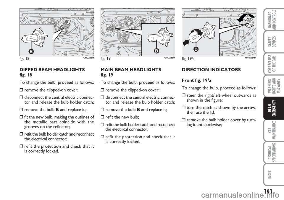
DIPPED BEAM HEADLIGHTS
fig. 18
To change the bulb, proceed as follows:
❒remove the clipped-on cover;
❒disconnect the central electric connec-
tor and release the bulb holder catch;
❒remove the bulb Band replace it;
❒fit the new bulb, making the outlines of
the metallic part coincide with the
grooves on the reflector;
❒refit the bulb holder catch and reconnect
the electrical connector;
❒refit the protection and check that it
is correctly locked.MAIN BEAM HEADLIGHTS
fig. 19
To change the bulb, proceed as follows:
❒remove the clipped-on cover;
❒disconnect the central electric connec-
tor and release the bulb holder catch;
❒remove the bulb Band replace it;
❒refit the new bulb;
❒refit the bulb holder catch and reconnect
the electrical connector;
❒refit the protection and check that it
is correctly locked.DIRECTION INDICATORS
Front fig. 19/a
To change the bulb, proceed as follows:
❒steer the right/left wheel outwards as
shown in the figure;
❒turn the catch as shown by the arrow,
then use the lid;
❒remove the bulb holder cover by turn-
ing it anticlockwise;
fig. 18F0R0222mfig. 19/aF0R0224mfig. 19F0R0223m
Page 164 of 230
163
WARNING
LIGHTS AND
MESSAGES
CAR
MAINTENANCE
TECHNICAL
SPECIFICATIONS
INDEX
DASHBOARD
AND CONTROLS
SAFETY
DEVICES
CORRECT USE
OF THE
CAR
IN AN
EMERGENCY
fig. 23/aF0R0228m
fig. 24F0R0230m
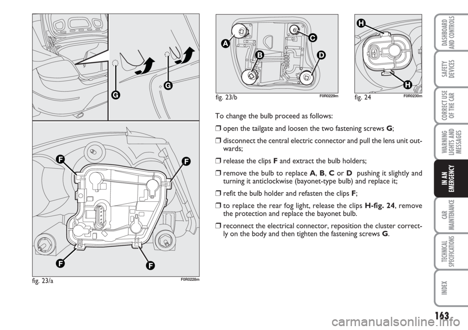
To change the bulb proceed as follows:
❒open the tailgate and loosen the two fastening screws G;
❒disconnect the central electric connector and pull the lens unit out-
wards;
❒release the clips Fand extract the bulb holders;
❒remove the bulb to replace A, B, Cor D pushing it slightly and
turning it anticlockwise (bayonet-type bulb) and replace it;
❒refit the bulb holder and refasten the clips F;
❒to replace the rear fog light, release the clips H-fig. 24, remove
the protection and replace the bayonet bulb.
❒reconnect the electrical connector, reposition the cluster correct-
ly on the body and then tighten the fastening screws G.
fig. 23/bF0R0229m
Page 165 of 230
164
WARNING
LIGHTS AND
MESSAGES
CAR
MAINTENANCE
TECHNICAL
SPECIFICATIONS
IINDEX
DASHBOARD
AND CONTROLS
SAFETY
DEVICES
CORRECT USE
OF THE
CAR
IN AN
EMERGENCY
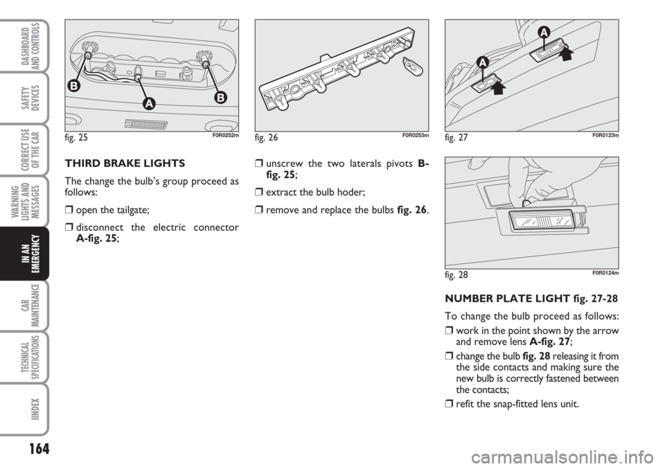
THIRD BRAKE LIGHTS
The change the bulb’s group proceed as
follows:
❒open the tailgate;
❒disconnect the electric connector
A-fig. 25;
❒unscrew the two laterals pivots B-
fig. 25;
❒extract the bulb hoder;
❒remove and replace the bulbs fig. 26.
NUMBER PLATE LIGHT fig. 27-28
To change the bulb proceed as follows:
❒work in the point shown by the arrow
and remove lens A-fig. 27;
❒change the bulb fig. 28releasing it from
the side contacts and making sure the
new bulb is correctly fastened between
the contacts;
❒refit the snap-fitted lens unit.
fig. 25F0R0252mfig. 26F0R0253mfig. 27F0R0123m
fig. 28F0R0124m