Clima FIAT MAREA 2000 1.G User Guide
[x] Cancel search | Manufacturer: FIAT, Model Year: 2000, Model line: MAREA, Model: FIAT MAREA 2000 1.GPages: 330
Page 126 of 330
Marea- Marea Weekend
2000 range ©
Auxiliary Units
Climate control
50
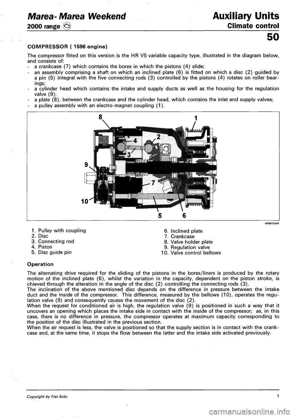
COMPRESSOR ( 1596 engine)
The compressor fitted on this version is the HR V5 variable capacity type, illustrated in the diagram below,
and consists of:
- a crankcase (7) which contains the bores in which the pistons (4) slide;
- an assembly comprising a shaft on which an inclined plate (6) is fitted on which a disc (2) guided by
a pin (5) integral with the five connecting rods (3) controlled by the pistons (4) rotates on roller bear
ings;
- a cylinder head which contains the intake and supply ducts as well as the housing for the regulation
valve (9);
- a plate (8), between the crankcase and the cylinder head, which contains the inlet and supply valves;
- a pulley assembly with an electro-magnet coupling (1).
1. Pulley with coupling
2. Disc
3. Connecting rod
4. Piston
5. Disc guide pin
6. Inclined plate
7. Crankcase
8. Valve holder plate
9. Regulation valve
10. Valve control bellows
Operation
The alternating drive required for the sliding of the pistons in the bores/liners is produced by the rotary
motion of the inclined plate (6), whilst the variation in the capacity, dependent on the piston stroke, is
chieved through the alteration in the angle of the disc (2) controlling the connecting rods (3).
The inclination of the above mentioned disc depends on the difference in pressure between the intake
duct and the inside of the compressor. This difference, measured by the bellows (10), operates the regu
lation valve (9) and consequently causes the movement of the disc (2).
When the request for conditioned air is high, the regulation valve (9) is positioned in such a way that it
uncovers an opening which places the intake side in contact with the inside of the compressor; as, in this
case, there is no difference in pressure, the compressor operates at maximum capacity corresponding to
the position of the disc illustrated in the previous section.
When the air request is less, the valve is positioned so that the supply section is in contact with the crank
case and, at the same time, it stops the flow between the latter and the intake side activated previously.
Copyright by Fiat Auto 1
Page 127 of 330
Auxiliary Units
Climate control
Marea-Marea Weekend
2000 range O
50
COMPRESSOR (1910 JTD)
The compressor fitted on this version is the SANDEN SD7V16 variable capacity type.
The capacity of the compressor varies starting from the maximum value (161.3 cm^/rev) and is gradually
reduced (up to 10.4 cm^/rev) according to the system load variations. - changed outside temperature
and/or humidity conditions or sharp variations in the engine load.
This solution is defined as "unlimited variable capacity".
The compressor is the alternating piston type: the variation in capacity is achieved by tilting the connect
ing rod holder plate with a consequent variation of the piston stroke: the movement of the plate is acti
vated by an internal regulation valve according to the balance of pressure upstream and downstream of
the compressor. In particular, a low intake pressure involves the shuttering of the compressor (reduced ca
pacity), whilst a high pressure involves operation at maximum power (maximum capacity).
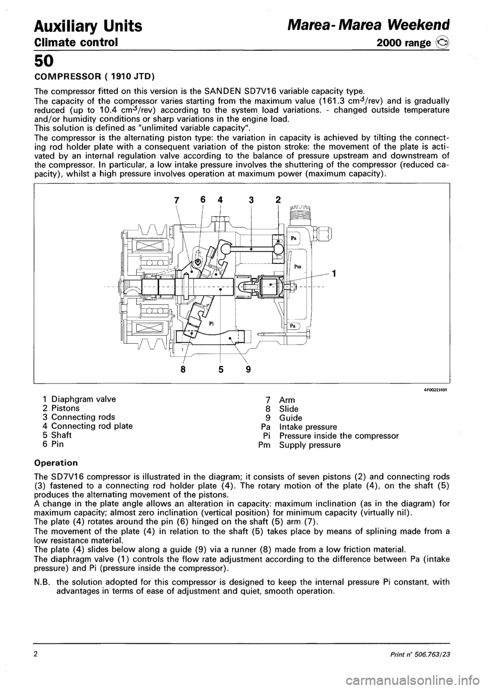
7 6 4 3 2
5 9
1 Diaphgram valve
2 Pistons
3 Connecting rods
4 Connecting rod plate
5 Shaft
6 Pin
7 Arm
8 Slide
9 Guide
Pa Intake pressure
Pi Pressure inside the compressor
Pm Supply pressure
Operation
The SD7V16 compressor is illustrated in the diagram; it consists of seven pistons (2) and connecting rods
(3) fastened to a connecting rod holder plate (4). The rotary motion of the plate (4), on the shaft (5)
produces the alternating movement of the pistons.
A change in the plate angle allows an alteration in capacity: maximum inclination (as in the diagram) for
maximum capacity; almost zero inclination (vertical position) for minimum capacity (virtually nil).
The plate (4) rotates around the pin (6) hinged on the shaft (5) arm (7).
The movement of the plate (4) in relation to the shaft (5) takes place by means of splining made from a
low resistance material.
The plate (4) slides below along a guide (9) via a runner (8) made from a low friction material.
The diaphragm valve (1) controls the flow rate adjustment according to the difference between Pa (intake
pressure) and Pi (pressure inside the compressor).
N.B. the solution adopted for this compressor is designed to keep the internal pressure Pi constant, with
advantages in terms of ease of adjustment and quiet, smooth operation.
2 Print n° 506.763/23
Page 128 of 330
Marea-Marea Weekend
2000 range ©)
Auxiliary Units
Climate control
50
COMPRESSOR ( 1998 engine)
The compressor fitted on this version is the SANDEN SD6V12 variable capacity type.
The capacity of the compressor varies starting from the maximum value (125.1 cnrfVrev) and is gradually
reduced (up to 6.2 cm /rev) according to the system load variations. - changed outside temperature
and/or humidity conditions or sharp variations in the engine load.
This solution is defined as "unlimited variable capacity".
The compressor is the alternating piston type: the variation in capacity is achieved by tilting the connect
ing rod holder plate with a consequent variation of the piston stroke: the movement of the plate is acti
vated by an internal regulation valve according to the balance of pressure upstream and downstream of
the compressor. In particular a low intake pressure involves the shuttering of the compressor (reduced ca
pacity), whilst a high pressure involves operation at maximum power (maximum capacity).
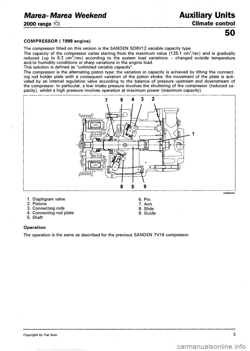
1. Diaphgram valve
2. Pistons
3. Connecting rods
4. Connecting rod plate
5. Shaft
6. Pin
7. Arm
8. Slide
9. Guide
Operation
The operation is the same as described for the previous SANDEN 7V16 compressor.
Copyright by Fiat Auto 3
Page 129 of 330
Auxiliary Units
Climate control
50
SPECIFICATIONS
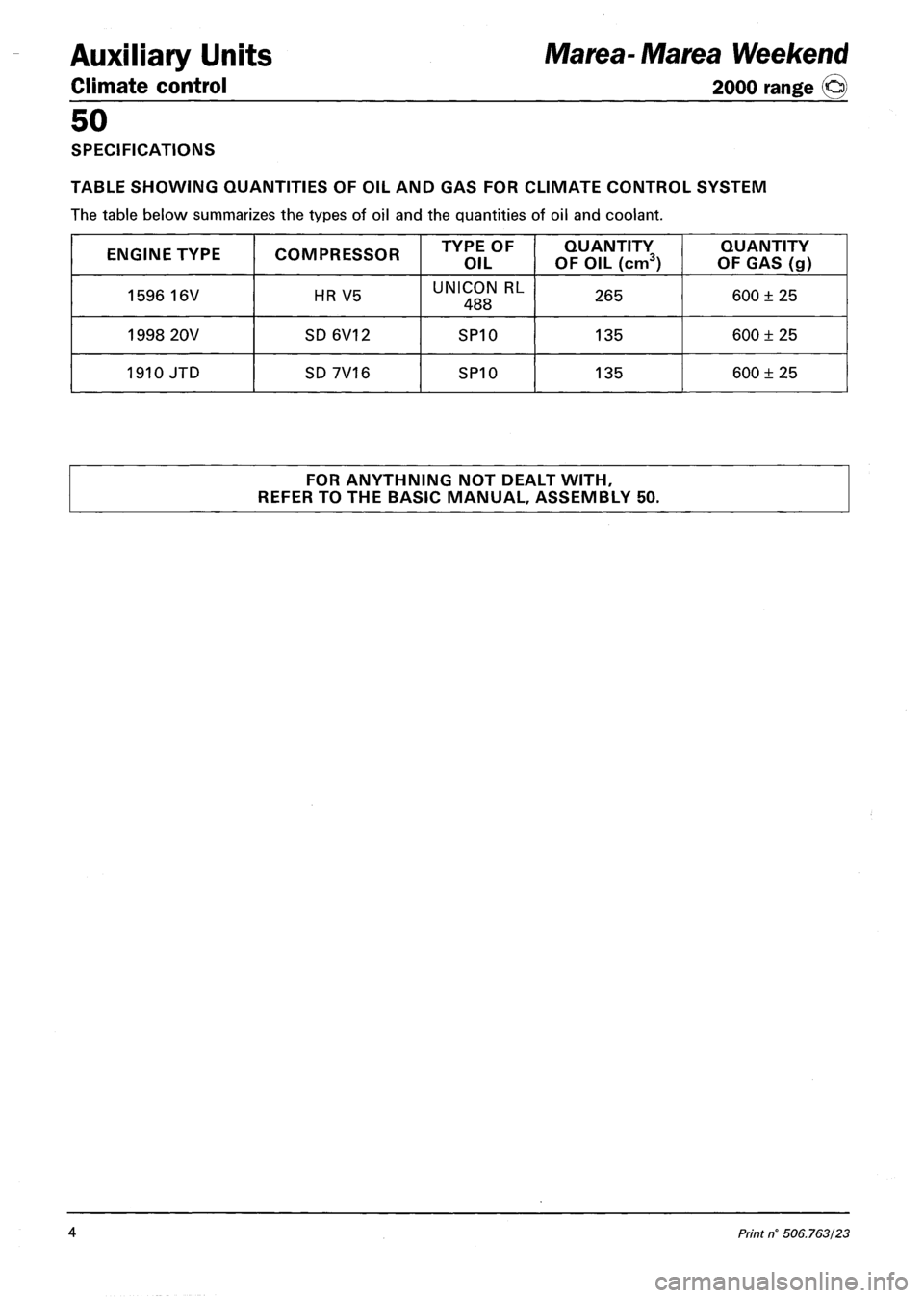
TABLE SHOWING QUANTITIES OF OIL AND GAS FOR CLIMATE CONTROL SYSTEM
The table below summarizes the types of oil and the quantities of oil and coolant.
ENGINE TYPE COMPRESSOR TYPE OF
OIL
QUANTITY
OF OIL (cm3)
QUANTITY
OF GAS (g)
1596 16V HR V5 UNICON RL
488 265 600 ± 25
1998 20V SD6V12 SP10 135 600 ± 25
1910 JTD SD 7V16 SP10 135 600 ± 25
FOR ANYTHNING NOT DEALT WITH,
REFER TO THE BASIC MANUAL, ASSEMBLY 50.
Marea-Marea Weekend
2000 range ©
4 Print n' 506.763/23
Page 137 of 330
Marea-Marea Weekend Electrical system
2000 range @ Junction unit
55.
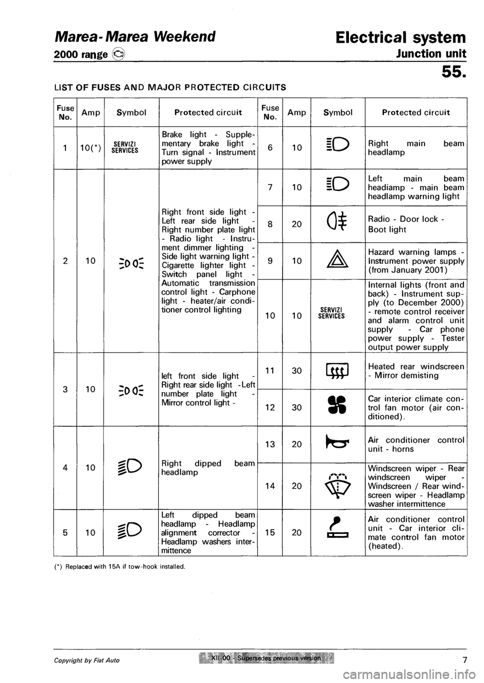
LIST OF FUSES AND MAJOR PROTECTED CIRCUITS
Fuse
No. Amp Symbol Protected circuit Fuse
No. Amp Symbol Protected circuit
1 ion SERVIZI SERVICES
Brake light - Supple
mentary brake light -
Turn signal - Instrument
power supply
6 10 ID Right main beam
headlamp
7 10 ID
Left main beam
headiamp - main beam
headlamp warning light
Right front side light -
Left rear side light
Right number plate light
- Radio light - Instru
8 20 0*
Radio - Door lock -
Boot light
2 10 3>
Side light warning light -
Cigarette lighter light -
Switch panel light -
9 10 A
Hazard warning lamps -
Instrument power supply
(from January 2001)
Automatic transmission
control light - Carphone
light - heater/air condi
tioner control lighting 10 10 SERVIZI SERVICES
Internal lights (front and
back) - Instrument sup
ply (to December 2000)
- remote control receiver
and alarm control unit
supply - Car phone
power supply - Tester
output power supply
3 10 -;o oi-
left front side light
Right rear side light -Left
11 30 Heated rear windscreen
- Mirror demisting
3 10 -;o oi-number plate light
Mirror control light -12 30 8
Car interior climate con
trol fan motor (air con
ditioned).
lO Right dipped beam
headlamp
13 20 Air conditioner control
unit - horns
4 10 lO Right dipped beam
headlamp
14 20
Windscreen wiper - Rear
windscreen wiper
Windscreen / Rear wind
screen wiper - Headlamp
washer intermittence
5 10 %o
Left dipped beam
headlamp - Headlamp
alignment corrector
Headlamp washers inter-
mittence
15 20 La
Air conditioner control
unit - Car interior cli
mate control fan motor
(heated).
(*) Replaced with 15A if tow-hook installed.
Copyright by Fiat Auto XII 00 - Supersedes previous version 7
Page 143 of 330
Marea- Marea Weekend
2000 range ©
Electrical equipment
Control module
55.
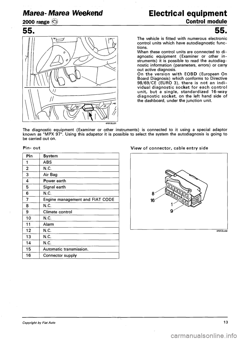
The vehicle is fitted with numerous electronic
control units which have autodiagnostic func
tions.
When these control units are connected to di
agnostic equipment (Examiner or other in
struments) it is possible to read the autodiag
nostic information (parameters, errors) or carry
out active diagnosis.
On the version with EOBD (European On
Board Diagnosis) which conforms to Directive
98/69/CE (EURO 3), there is not an indi
vidual diagnostic socket for each control
unit, but a single.- standardized 16-way
diagnostic socket, on the left hand side of
the dashboard, under the junction unit.
The diagnostic equipment (Examiner or other instruments) is connected to it using a special adaptor
known as "MPX 97". Using this adapator it is possible to select the system the autodiagnosis is going to
be carried out on.
Pin- out View of connector, cable entry side
Pin System
1 ABS
2 N.C.
3 Air Bag
4 Power earth
5 Signal earth
6 N.C.
7 Engine management and FIAT CODE
8 N.C.
9 Climate control
10 N.C.
11 Alarm
12 N.C.
13 N.C.
14 N.C.
15 Automatic transmission.
16 Connector supply
Copyright by Fiat Auto 13
Page 185 of 330
Electrical system Marea-Marea Weekend
Wiring diagrams 2000 range (jcj)
55.
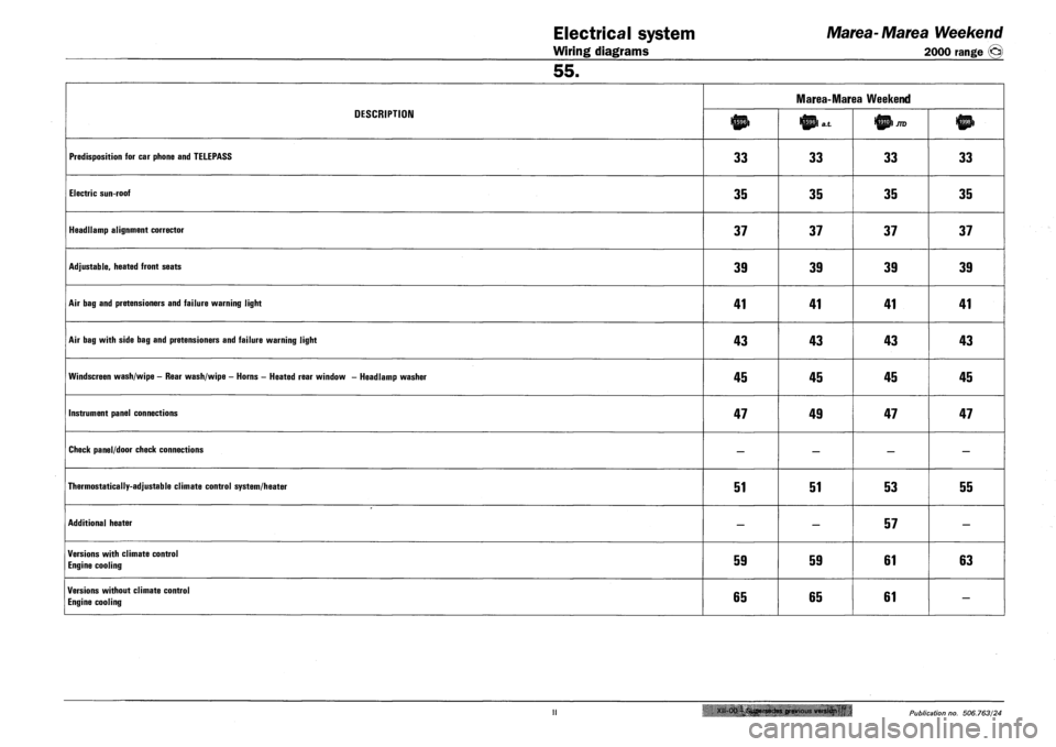
DESCRIPTION
Marea-Marea Weekend
DESCRIPTION lnp> Ittpl a.t
PREDISPOSITION FOR CAR PHONE AND TELEPASS 33 33 33 33
ELECTRIC SUN-ROOF 35 35 35 35
HEADLLAMP ALIGNMENT CORRECTOR 37 37 37 37
ADJUSTABLE, HEATED FRONT SEATS 39 39 39 39
AIR BAG AND PRETENSIONERS AND FAILURE WARNING LIGHT 41 41 41 41
AIR BAG WITH SIDE BAG AND PRETENSIONERS AND FAILURE WARNING LIGHT 43 43 43 43
WINDSCREEN WASH/WIPE - REAR WASH/WIPE - HORNS - HEATED REAR WINDOW - HEADLAMP WASHER 45 45 45 45
INSTRUMENT PANEL CONNECTIONS 47 49 47 47
CHECK PANEL/DOOR CHECK CONNECTIONS — — — —
THERMOSTATICALLY-ADJUSTABLE CLIMATE CONTROL SYSTEM/HEATER 51 51 53 55
ADDITIONAL HEATER — — 57 —
VERSIONS WITH CLIMATE CONTROL
ENGINE COOLING 59 59 61 63
VERSIONS WITHOUT CLIMATE CONTROL
ENGINE COOLING 65 65 61 —
Xll-Oa-i.Supersedes previous version 'u • Publication no. 506.763/24
Page 237 of 330
Marea-Marea Weekend
2000 range ®
Electrical equipment
Wiring diagrams
55.
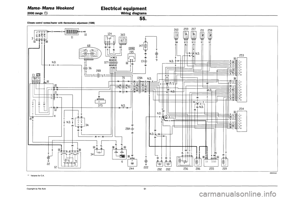
Climate control system/heater with thermostatic adjustment (1596)
„ _ (U -j ^ Z QD pq ID 5T ^
259 207 211 258
Variants for C.A.
Copyright by Fiat Auto 51
Page 238 of 330
Electrical equipment
Component location
Marea- Marea Weekend
2000 range ®
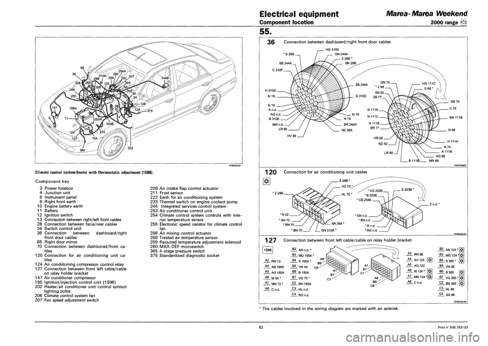
Climate control system/heater with thermostatic adjustment (1596)
Component key
3 Power fusebox
4 Junction unit
6 Instrument panel
9 Right front earth
10 Engine battery earth
11 Battery
12 Ignition switch
13 Connection between right/left front cables
28 Connection between facia/rear cables
34 Switch control unit
36 Connection between dashboard/right
front door cables
68 Right door mirror
70 Connection between dashborad/front ca
bles
120 Connection for air conditioning unit ca
bles
124 Air condiitoning compressor control relay
127 Connection between front left cable/cable
on relay holder bracket
147 Air conditioner compressor
195 Ignition/injection control unit (1596)
202 Heater/air conditioner unit control symbol
lighting bulbs
206 Climate control system fan
207 Fan speed adjustment switch
209 Air intake flap control actuator
211 Frost sensor
222 Earth for air conditioning system
233 Thermal switch on engine coolant pump
244 Integrated services control system
253 Air conditioner control unit
254 Climate control system controls with inte
rior temperature sensor
255 Electronic speed variator for climate control
fan
256 Air mixing control actuator
258 Treated air temperature sensor
259 Required temperature adjustment solenoid
260 MAX-DEF microswitch
365 4-stage pressure switch
375 Standardized diagnostic socket
55.
36 Connection between dashboard/right front door cables
* S 28B.
HG310D
GN 244A
Z28B
N 19 _
A n.d.
AG n.d
B310E
MN n.d.
LR66
BN 111B
HV66
AG 68
MN 68
1 20 Connection for air conditioning unit cables
1Z 28B.
*N22.
"AN 70
' RN 70.
. Z n.d.
127
1596
Connection between front left cable/cable on relay holder bracket
62 AN n.d. *
B3 MG 195A*
A2 RN 13 B4 S195A*
A4 AB 195A B5 VN3A
A5 AG 195A B6 B195A
A6 M3A* B7 VG70*
A7 MN 13* C2 BN 195A
A8 Cn.d. C3 HL n.d.
C4 SG n.d.
RN 98
_AlAV123 g*]
A5 AG 122
_A6_ M 124 * [§]
JiL MN 124 *[§]
_*!L C n.d.
_§?_ AN 124*[§]
_B3_MG 124 *§]
-US 365* [$]
J*!LVN98
J?6. B 365 [ffi
_g7_ VG 365*[
_Pi_ HL98
_?i_SG 98
The cables involved in the wiring diagram are marked with an asterisk.
52 Print n° 506.763/23
Page 239 of 330
Marea-Marea Weekend
2000 range ©
Electrical equipment
Wiring diagrams
55.
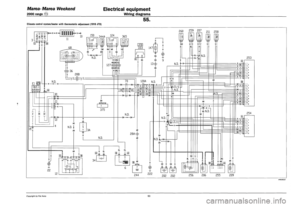
Climate control system/heater with thermostatic adjustment (1910 JTD)
XXX X
—J I—I _^ —£
3— R — R —
B M R
111111 *
260 259 207
11
10 150 344A 124
El la^SI
86 85 308787
t
n 1 1
68
frfl 87 30 85 86
-QZ5—| [—Wv-
frTI 87 30 85 86
365
RN RN
L-RN-fr-RN 1
N.D,
AR MN | AR | VG
M KG
c^36
N.D.
s 28B
LLki
MN
1271£
MN
MG
AR
AR
MG
15 12
1-9-RN-•3-p-AN-
rjj
|-AG-
I- N -
E
rw-p-GN-
m
BN
375
AG
N.D. |
AN 3A
N.D,
JTD
333 147
60 18
MG
VG
VG
MN I MN
13^
MN
TjZT
AN
B
1*1
N S
BL
N
N.D. '~B
70
-RN-
1—VG; -AN-
-RN-
120A N.D.
-AN-
^RN_-
Z
-HL
-BN-
VG VG--AN-
I—GN HL-
N.D.
-GN—•—GN—1
-RG-
-CB--GN-
BN-
VG
28A
AR
+
AR
AN
12
few
I 15/54 I I
.H
„„ 15/54 ' ,1, !nt/a J pos 30 50 Int s-tazH 34
N GL
JL
GL HL
21 16
L,
s JL
17
(55
244
^ N.D,
HN
N.D.
— N -
NZ
N
GN
N.D. j^RN-
GN
N
222
GN—i
- + c
w
211 258
N V
R
N.D.
HN G
BL
GN N GN N
n n
N
AB
N.D,
AN
-RG-R —
RG N,D,
AN
RG
N AN
202 202 256 206
12 12 3 4
255
253
-AB-
i— L
-VG CB-
BL-
-NZ-
- S -
-HN-
m
-RG-
|---VG-
-AR-
-CB-fe-
254
-HN-
- B -
- Z -
-RG
-BN-RN-
L —fe-
AR
209
Copyright by Fiat Auto 53